HAL Id: hal-00640497
https://hal.archives-ouvertes.fr/hal-00640497
Submitted on 12 Nov 2011
HAL is a multi-disciplinary open access
archive for the deposit and dissemination of
sci-entific research documents, whether they are
pub-lished or not. The documents may come from
teaching and research institutions in France or
abroad, or from public or private research centers.
L’archive ouverte pluridisciplinaire HAL, est
destinée au dépôt et à la diffusion de documents
scientifiques de niveau recherche, publiés ou non,
émanant des établissements d’enseignement et de
recherche français ou étrangers, des laboratoires
publics ou privés.
The PICARD/SODISM Pointing Mechanism: From the
Design to the Flight Performances
Mustapha Meftah, Abdanour Irbah, R. Le Letty, A. Bataille, Emmanuel
Ducourt, Germain Poiet, M. Privat
To cite this version:
Mustapha Meftah, Abdanour Irbah, R. Le Letty, A. Bataille, Emmanuel Ducourt, et al.. The
PI-CARD/SODISM Pointing Mechanism: From the Design to the Flight Performances. ESMATS 2011,
14th European Space Mechanisms and Tribology Symposium 2011, Sep 2011, Constance, Germany.
8 pp. �hal-00640497�
THE PICARD/SODISM POINTING MECHANISM:
FROM THE DESIGN TO THE FLIGHT PERFORMANCES
M. Meftah(1), A. Irbah(1), R. Le Letty(2), A. Bataille(2), E. Ducourt(1), G. Poiet(1), M. Privat(3)
(1) CNRS, INSU, LATMOS-IPSL, Université Versailles St-Quentin, Guyancourt, France, Email: Mustapha.Meftah@latmos.ipsl.fr
(2) Cedrat Technologies SA, 15 ch. De Malacher, ZIRST – Inovallée, 38246 Meylan, France (3)
CNES, 18 avenue Edouard Belin, 31401 Toulouse, France
ABSTRACT
PICARD is a French space scientific mission. Its objectives are the study of the origin of the solar variability and the study of the relations between the Sun and the Earth's climate. The Satellite was successfully launched, on June 15, 2010 on a DNEPR launcher from Dombarovskiy Cosmodrome, near Yasny (Russia). The payload consists in two absolute radiometers measuring the total solar irradiance and an imaging telescope to determine the solar diameter and asphericity.
SODISM (SOlar Diameter Imager and Surface Mapper) is a 11 cm Ritchey-Chretien imaging telescope associated with a CCD, taking solar images at five wavelengths. It carries a four-prism system to
ensure a metrological control of the optics
magnification. The first image of the Sun with this new instrument was taken on July 22, 2010. A mechanism of this instrument is the subject of the presentation. Current and future space telescope mission require ever-higher dimensionally stable structures. CNRS aims to design, manufacture and test a very high dimensional stability telescope for precision optical systems using advanced materials combining high dimensional stability and good structural performance. To achieve these accurate measurements, SODISM includes a fine pointing mechanism, based on the piezoelectric technology.
This paper covers the description of the SODISM instrument, the design and the qualification of the
pointing mechanism, and the flight results
(commissioning phase and in orbit validation phase).
1. INTRODUCTION
The Sun is a huge, glowing ball at the center of our solar system. The Sun provides light, heat, and other energy to Earth. Without the Sun, there would be no life on Earth. The Sun is made up entirely of gas. Most of it is a type of gas that is sensitive to magnetism. This sensitivity makes this type of gas so special (plasma). Earth travels around the Sun at an average distance of about 149,597,870 kilometers at one Astronomical Unit (A.U.) from it.
The Sun's radius (distance from its center to its surface) is about 695,680 kilometers at 1 A.U. (near 959.2 arcseconds), approximately 109 times Earth's radius. It varies slightly from pole to equator due to its rotation,
which induces an oblateness less than 10
milliarcseconds (mas).
The Sun’s activity is not constant but varies over an 11-year cycle. The 11-year sunspot cycle is related to a 22-year cycle for the reversal of the Sun's magnetic field. The level of solar activity can be quantified by monitoring sunspots. These are regions on the Sun’s surface where the temperature is lower (dark appearance), caused by intense magnetic activity. The Sun's magnetic fields rise through the convection zone and erupt through the photosphere into the chromosphere and corona. The eruptions lead to solar activity, which includes such phenomena as sunspots, flares, and coronal mass ejections.
Solar Cycle 24 is the 24th solar cycle since 1755, when recording of solar sunspot activity began. This would make it the least active cycle since solar cycle 6, which ended in the year 1823.
Why measure the Sun’s diameter?
Jean PICARD (1620-1682), a French astronomer of the Seventeenth century measured the solar diameter, observed the sunspots and determined the Sun rotation velocity. The PICARD mission took the name of the astronomer. The solar diameter has been measured for 3.5 centuries and its variation with the solar activity has been the subject of much research. Data has shown the diameter variation to be in phase, anti-phase, or without any correlation to the solar activity. As the data were gathered from ground, the atmosphere was claimed to be the cause of the above inconsistencies and discussed in Thuillier et al. [1]. But is there a direct link between the Sun’s diameter, solar activity and Earth’s climate?
Today, the solar diameter variability is questionable. One of the primary objectives of the PICARD mission is to measure the solar diameter and shape with an accuracy of a few mas in orbit to avoid all atmospheric influence.
_________________________________________________
The solar mission PICARD will simultaneously measure several key parameters of the Sun.
The scientific objectives of the PICARD mission are described in details by [2].
These parameters are essential for the understanding of the physics of the Sun. The PICARD microsatellite mission will provide two to three years simultaneous measurements of the diameter and the solar asphericity at several wave-lengths (215, 393.37, 535.7, 607.1 and 782.2 nm), the limb shape at the same wavelengths, the differential rotation, the Total Solar Irradiance (TSI), the Spectral Solar Irradiance (UV, visible, IR), the solar oscillation (helioseismology) and the variation of these quantities as a function of the solar activity. To achieve these very precise measurements, it is necessary to stabilize images of the Sun on the CCD. Sun pointing accuracy of the Satellite, initially insufficient, was significantly improved thanks to a solar tracking sensor with 36 arcseconds precision. The PICARD/SODISM pointing mechanism accuracy is achieved thanks to a piezoelectric system acting on the telescope primary mirror which allows to stabilize the Sun image on the CCD with an accuracy of 0.2 arcseconds. This system is composed of three piezoactuators PPA40M from CEDRAT Technologies, that are modified to get a higher mechanical preload and include N17 piezoceramics.
The PICARD mission operate during the solar cycle 24 allowing us to study the relationship between all the measurements simultaneously gathered, in particular between the diameter and the solar luminosity.
The orbit is chosen to allow periods of Sun visibility as long as possible. A SSO (Sun Synchronous Orbit) with an ascending node at 06h00, an altitude of 735 km (period of 99 minutes) and an inclination of 98 degrees was selected. The duration of eclipses will not exceed 20 minutes with these orbit parameters, in particular in December. The mission lifetime is two years; however a longer mission is expected especially given the late start of cycle 24.
2. THE SODISM INSTRUMENT
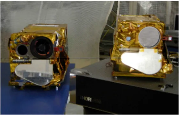
SODISM (shown in Figure 1) is an 11-cm diameter telescope associated with a 2048x2048 pixels CCD detector. The instrument is described in details by [3]. The instrument field of view and its angular resolution are respectively about 35 arcminutes and 1.06 arcseconds.
Given that the solar shape in the photospheric continuum is nearly perfectly circular (the solar asphericity is about 10 mas), the image on the detector provides 1000 diameter or more measurements registered at different positions within each pixel. Using this set of measurements, the pixellization effect is averaged and the diameter can be obtained with a precision of a few mas, with however limitations due to the noise, flatfield and optical distortion, which have to
be independently calibrated. SODISM observes the Sun in five wavelength domains by using interference filters.
Figure 1. SODISM instrument
Qualification Model (left) and Flight Model (right)
The SODISM optical system (shown in Figure 2) consists of an entrance window (curved window in silica back coated with a density filter), a primary mirror M1, a secondary mirror M2 both in zerodur, several interference filters, and a CCD. The telescope uses Carbon/Carbon for reasons of dimensional stability [4].
Figure 2. SODISM optical system
The Sun image is stabilized on the detector by a three-level optical system, i) stars are used to achieve a prepointing within a few degrees, ii) a four-quadrant system (solar tracking sensor) achieves a pointing within +/- 36 arcseconds with a maximum drift of 5 arcseconds per second, iii) a part of the image provided by each prism is used through a four-diode system whose signals allow centering the Sun image on the CCD with +/- 0.2 arcseconds precision.
The optical system of SODISM includes four optical prisms that will create four auxiliary images located in each corner of the CCD. The reference instrument scale factor is provided by the prisms. The four prisms' temperature must be stable to better than 0.5°C. The absolute angular reference is provided by using stars having an angular distance comparable to the Sun diameter.
These observations are made every three months by rotating the spacecraft toward couples of bright stars (9 couples are selected). Using 20 images, an accuracy of few mas can be achieved.
3. THE POINTING MECHANISM
3.1.Description of the mechanism
For the fine pointing, SODISM uses three piezoelectric devices acting on the primary mirror M1.
The pointing mechanism design is shown in Figure 3.
Figure 3. The pointing mechanism
Piezo-electric actuators (Cedrat Technologies) have been modified to get a higher mechanical preload and include piezoelectric ceramics. The parallel pre-stressed actuator is a preloaded stack of low voltage piezoelectric ceramics. Piezoelectric displacement is 50 µ m peak for 170 V peak. The capacitance of the piezoelectric is 2.7 µF. A tensile force test was performed to verify that the mechanical prestress is effectively applied to the correct level. The power consumption depends upon the quality of the pointing. Strain gauges are used for each piezoelectric (repeatability on the positioning). For the fine pointing, SODISM uses four photodiodes (API SD9973). Any unbalanced signal between pairs of detectors indicates a modification of the pointing. Photodiodes are semiconductors that generate a current or voltage when illuminated by light. A sapphire window is used. Sapphire is a very rugged radiation resistant optical material with a very broad transmission range. In our application, there is a preamplifier with a gain of 1 Megohm. The range of SODISM pointing is between 500 nm and 600 nm.
The photodiode responsivity is near 0.275 A/W (or 0.275 V/µW) for this range of application. The stability of the photodiode responsivity is fundamental for the pointing. A lot of qualification tests have been performed to verify this stability. The photodiodes are compatible with a 2 krad total dose (200 rad per hour) at photodiodes level equivalent to LEO (735 km) for 2-year missions. A proton test has been performed (1
device: E=200 MeV, Phi=1010 protons/cm2 and 2
devices: E=60 MeV, Phi=1010 protons/cm2). Other tests
have been performed (aging tests, burn in, thermal cycling, shocks, vibration, …). The photodiode responsivity and major electrical parameters remain stable after these tests.
The telescope has a mirror M1 active actuated by three piezoelectrics to handle 2 active axes (Rx, Ry), Z being the axis of translation (Figure 4). Activation of the M1 mirror helps isolating the telescope movements of the platform, via an optical sensor: that is formed by a secondary beam passing through the telescope (and therefore sensitive to the activation of M1) and sent on an electro-optical sensor (guide way). The piezoelectric actuators are linearized by strain gauges.
Figure 4. Cut of the pointing mechanism
The main characteristics of the fine pointing are: the ability to have an offset alignment four-quadrant system / SODISM optical path of +/- 10 arcseconds, pointing accuracy of +/- 0.2 arcseconds, stability of the summit of the primary mirror in Z (optical axis) of +/- 0.2 µ m and ability to image offset of +/- 20 arcseconds. It is possible to fix the error signal photodiodes by offset (equivalent to a sliding): +/- 60 arcseconds. The fine pointing is operational two seconds before taking the picture on the CCD and the functioning of the shutter.
The pointing mechanism has been built by CNRS – LATMOS (ex Service d’Aéronomie). A Qualification Model (QM) of the pointing mechanism is shown in Figure 5.
3.2.Piezo Actuator PPA40M-NM-SV
The pointing mechanism of SODISM uses piezo actuators PPA40M-NM-SV (Figure 6).
The parallel pre-stressed actuator is a preloaded stack of low voltage piezoelectric ceramics. The preload (or pre-stress) is obtained from an external spring frame made of stainless steel which protects the MultiLayer Actuator (MLA) against tensile force and provides mechanical interfaces for the user allowing an easier integration. This pre-stressing frame applies an optimal preloading force to the MLA, which ensures a longer lifetime and better performance with dynamic applications than traditional preloaded actuators. Designed by the CEDRAT, this modified direct piezo actuator results from contracts carried out for CNES and CNRS.
Figure 6. View of the Direct Piezo Actuator used in SODISM/PICARD
Multilayer piezo component is shown in Figure 7. Piezoelectric devices have the unique property of generating a voltage when a pressure is applied, as well as the inverse property, expanding when a voltage is applied. Laser and photonics applications generally rely upon the latter: converting a voltage to a very accurate displacement for processes such as alignment of a fiber to a device or waveguide, control of the tilt of a harmonic crystal, making laser-cavity length adjustments, or scanning a tunable diode laser.
Figure 7. Top view of 5*5*10 mm Multilayer piezo component (N17 type)
When a voltage is applied to a cylindrical piezoelectric element, the cylinder increases in length (and decreases in diameter). This expansion is a percent of the total length L of the cylinder. And because the total length of a piezoelectric element is relatively small, the resulting change in total length is much smaller (in the nanometer range), which is good for applications that
need high resolution across relatively short
displacements.
To increase the total travel and retain similar nanometer-scale resolution, piezoelectric elements can be stacked and voltage applied to elements in parallel such that the total length increases, yielding displacements in the micron range.
One way to increase the travel further is to stack piezoelectric elements and add a leveraging system. Travel can extend to the 20, 100, or even 200 µ m range. Such leveraged displacements apply less force, but they are still generally suitable for applications such as automated alignment of fibers and waveguides. For PICARD/SODISM application, we have chosen a stroke of nearly 50 µ m.
The properties defined in the Table 1, are set up according to the technical conditions of use and measurement. These properties are warranted within their variation range and in compliance with the standard technical conditions of use.
Nominal values External force maximum
traction (non operating) 800 N External force maximum
compression (non operating) 1600 N Non operating
temperatures -40°C / +50°C Operating
temperatures -20°C / +30°C Operating temperatures with
performances +10°C / +30°C Table 1-a: Technical conditions of use
Nominal values Displacement (voltage between -20V to 150V) 48.5 µm Blocked force (at 150V) 950 N Pre-Stress
(Operating temperatures) 35 MPa +/-2.1 Pre-Stress
(Non operating temperatures) 32.3 at 38.7 MPa Minimum stress in the ceramic
(compression) 4.5 MPa Maximum stress in the ceramic
(compression) 95 MPa Maximum stress
for the spring 630 MPa Volume 48*12*10 mm
Weight 17.1 g Table 1-b: Main measurements
3.3.Pointing mechanism characteristics
The pointing mechanism is operated by global on-board electronics named the PGCU (PICARD Gestion Charge Utile).
Table 2 summarizes the main characteristics of the mechanism.
Solar images are recorded every minute with SODISM and processed on-board. Every minute, the pointing mechanism is operational.
Main characteristics Volume 153*141*125 mm Weight 2.54 kg Power consumption 2.0 W
Pointing accuracy +/- 0.2 arcseconds Offset (rotation Rx, Ry) +/- 60 arcseconds Table 2: Pointing mechanism main characteristics
4. THE PIEZO QUALIFICATION
A method has been used to qualify components. It is described in Figure 8.
A Lot Acceptance Tests (LAT) was developed and includes:
- A Destructive Physical Analysis (DPA) (and comparison with previous results) of the piezo multilayer components to be used in the program PICARD/SODISM,
- A tensile force test,
- The DPA resulting from the encountered anomaly.
Figure 8. LAT test flow
As an applicable ESCC standard document does not yet exist, the standard applicable for multilayer capacitors was used to derive an appropriate qualification program.
The piezoelectric components are divided into 4 groups:
- Control group: stroke, blocked force, electrical characteristics and a DPA,
- Electrical tests group: functional test under UHV, Paschen effect, electrical strength,
- Mechanical tests group: thermal shocks, fatigue, traction/compression strength,
- Humidity tests groups: this represents a life test under humid environment (40% Rh, 60% Rh and 85% Rh), which is the most critical environment for piezoelectric in use.
The main conclusion is that one piezoelectric passes the evaluation without any failure and the other one passes all the tests but not the high humidity level life test (85% Rh). This last result implies user guidelines during AIT (Assembling, Integration and Tests) operations. The influence on performance and reliability of the use of cleaning solvent was also evaluated. Part of the piezoelectric qualification was done during this campaign. Other aspects of qualification have been validated by PICARD project. The 2 sources of piezoelectric ceramics tested are preferred components for CNES applications. One of these sources is used on the Picard satellite telescope. More recently, the application of the Reduction Of
Hazardous Substances (Rohs) on piezoelectric
component has lead to problems. The piezoelectric material itself often contains lead oxides that are exempted from this directive. However, the soldering
connections are concerned: non-lead soldering
connections are more difficult, due to a higher temperature.
The Figure 9 shows an example of a non lead soldering connection of bad quality that is also responsible for a crack occurrence.
Figure 9. Cut of view of a soldering connection
The aerospace industry requires such destructive Physical Analysis to be performed for each production lot, to monitor the quality assurance product. As a consequence, all the soldering (both for the piezo and the strain gauges) connections are performed and controlled at Cedrat Technologies (Figure 10).
Performing space qualified soldering connections
Thermal vacuum test
Fatigue test DPA N°1 Initial lot Tensile test DPA N°3 DPA N°2
Figure 10. View of a soldering and secured connection
The tested lot of 28 components of the N17 component was divided into 4 groups and the evaluation test program was completed according to the test plan. No failure has been encountered, despite relatively long humidity resistance tests [5].
The realized fatigue test included the following set of cycles (Table 3):
- First sample: 4.106 cycles,
- Second sample: 20.106 cycles.
Displacement Resonance Before fatigue test After fatigue test Before fatigue test After fatigue test PPA20M 06-009 23.48 µm 23.21 µm 39484 Hz 39902 Hz PPA20M 06-010 22.64 µm 22.64 µm 38876 Hz 39142 Hz Table 3: Outcome of the functional tests before and
after the vibration tests
5. QUALIFICATION PERFORMANCES
The mechanism has been qualified through a dedicated test campaign.
Environments for the qualification and acceptance of the mechanism are:
- Ariane sine, - DNEPR random,
- Shock (Solar array release with pyrosofts nuts and separation of the satellite with pyro devices),
- Thermal environment of SSO at 735 km, - Functional tests.
5.1.Mechanical environment
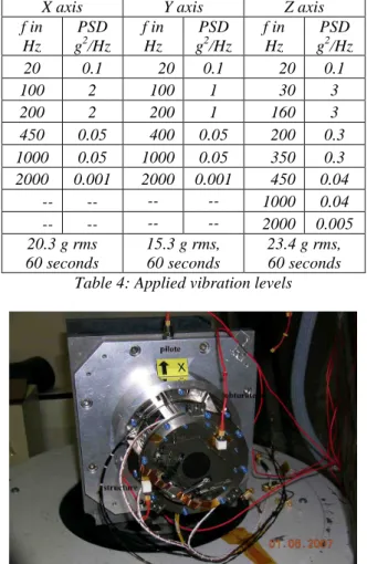
The mechanism was designed to withstand the launch loads. Random levels are displayed in the Table 4 and have been successfully tested (Figure 11).
Those levels were defined after a mechanical analysis of the coupling between the SODISM instrument and the pointing mechanism.
The design was assessed by using a Finite Element Model of the pointing mechanism.
A random vibration has been achieved on the mechanism with the levels given in the Table 10.
X axis Y axis Z axis f in Hz PSD g2/Hz f in Hz PSD g2/Hz f in Hz PSD g2/Hz 20 0.1 20 0.1 20 0.1 100 2 100 1 30 3 200 2 200 1 160 3 450 0.05 400 0.05 200 0.3 1000 0.05 1000 0.05 350 0.3 2000 0.001 2000 0.001 450 0.04 -- -- -- -- 1000 0.04 -- -- -- -- 2000 0.005 20.3 g rms 60 seconds 15.3 g rms, 60 seconds 23.4 g rms, 60 seconds Table 4: Applied vibration levels
Figure 11. View of the Pointing Mechanism on the shaker
5.2.Shock test
A shock test was achieved on MST Satellite (Mechanical and Thermal Structure of the Satellite) for a solar array release with pyrotechnics nuts and separation of the microsatellite with pyrotechnics devices.
This test allowed qualifying the instrument SODISM with the pointing mechanism.
5.3.Thermal environment
The thermal environment was established within the following thermal environment: -35°C / +50°C (non operational).
For operational conditions, the pointing mechanism thermal cycling was between +5°C and +40°C.
8 Thermal-vacuum cycles have been performed.
5.4.Functional test at instrument level
To obtain a on-ground validation of the closed loop implemented in the mechanism, a dedicated test bench
simulating the change of the sun position has been used (Figure 12).
The Figure 13 shows qualitatively the effect of the pointing mechanism on the quality of the image. The optical closed loop is realised by means of the 4 photodiodes.
Figure 12. Test bench of SODISM instrument
Figure 13. View of the simulated Sun Without the pointing mechanism (left) With the pointing mechanism (right)
The characteristics of each piezo actuator (used on the flight model of the mechanism) were measured (Table 5 show main characteristics).
Displacement vs. Input voltage Piezo Actuator PPA40M – N°1 50.04 µm pk-pk for 170 V pk-pk Piezo Actuator PPA40M – N°2 50.39 µm pk-pk for 170 V pk-pk Piezo Actuator PPA40M – N°3 50.84 µm pk-pk for 170 V pk-pk Table 5: Maximum measured displacement
6. FLIGHT PERFORMANCES
The satellite is on a 735 km Sun Synchronous Orbit (06h00-18h00). This means short eclipses during three months in one year. They are limited to few minutes up to 20 minutes at maximum in December. The image of the Sun shown in Figure 14 has been recorded with SODISM. It has been processed to correct the main optical and radiometric defaults of the raw image. This image enables to visualize several features such as sunspots. This image confirms the increase of the solar activity. The sunspots appear at high solar latitude and move slowly towards the solar equator, their number increasing with the solar activity.
Figure 14. Image of the Sun taken by SODISM instrument
An image is taken every 2 minutes, leading to 720 images per day. The Figure 15 shows the angular deviations performed by the pointing mechanism over 3 days. One can deduce the chronogram (Figure 16) and see that the Gaussian distribution. This correction is attributed to the disturbances coming form the spacecraft attitude. The standard deviation is equal to 0.31 pixel (whose size corresponds to 1.06 arcsecond). This means that the image stability (standard deviation) corresponds to an angular value of +/- 0.234 arcsecond. The initial specification was +/- 0.2 arcsecond.
It can be concluded that the pointing mechanism implemented and qualified in the SODISM instrument is effective. 1033 1033.25 1033.5 1033.75 1034 1034.25 1034.5 1034.75 1035 1035.25 1035.5 1035.75 1036 1028 1028.25 1028.5 1028.75 1029 1029.25 1029.5 1029.75 1030 1030.25 1030.5 1030.75 1031 Y p o si o n o f th e C C D [p ix e ls ]
X posi on of the CCD [pixels]
Posi on of the centers of images taken by SODISM instrument (at 535 nm) (16, 17 and 18 april 2011)
Figure 15. Angular correction performed by the pointing mechanism for 3 flight days of operation
0 0.2 0.4 0.6 0.8 1 1.2 1.4 1033 1033.5 1034 1034.5 1035 1035.5 1036 1036.5 D en si ty center Y [pixel] Histogramm
center Y (pixel) Normale(1034.409;0.310)
Figure 16. Histogram of the angular correction performed by the pointing mechanism
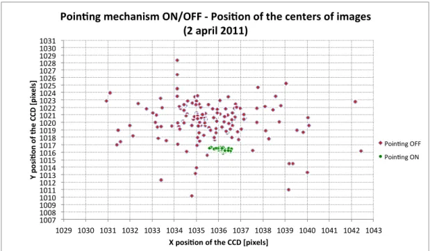
The Figure 17 shows the improvement brought by the pointing mechanism and its effect on the achieved image stability.
An image is taken every 2 minutes, leading to 720 images per day.
This test is used to characterize the effects of pointing mechanism on the quality of images.
7. CONCLUSION
An accurate pointing mechanism based on piezo actuators has been developed and qualified to compensate for the PICARD spacecraft disturbances. The flight results are in accordance with the on ground results. Such pointing mechanism is thus very effective to implement an accurate telescope on a spacecraft platform including some noises.
The image stability (standard deviation) corresponds to an angular value of +/- 0.23 arcsecond.
The PICARD/SODISM mechanism is in orbit since one year and is operational.
8. ACKNOWLEDGMENTS
We thank CEDRAT, CNES (Centre National d’Etudes Spatiales) and CNRS (Centre National de la Recherche Scientifique) for their support as well as all participants having devoted their expertise to this project. We wish to express our gratitude to all CNES and CNRS members who participated to the preparation of this mission.
The PICARD development has been made possible by funding from the CNES and the CNRS. We would like to acknowledge the whole PICARD project team who has done a remarkable work towards a successful mission. We thank our collaborators for the design and fabrication of the mechanism, including the important help of Mireille Meissonnier, Pierre Bourget, Emmanuel Bertran, Paul Ferrero and Claude Leroy.
9. REFERENCES
1. G. Thuillier, S. Sofia, M. Haberreiter and the
PICARD team, Past, Present and Future
Measurements of the Solar Diameter, Adv. Space Res. 35, 329-340, 2005.
2. G. Thuillier, S. Dewitte, W. Schmutz and the PICARD team, Simultaneous Measurements of the Total Solar Irradiance and Solar Diameter by the PICARD mission, Adv. Space Res. 1792-1806, 2006.
3. M. Meftah et al., The space instrument SODISM and the ground instrument SODISM II, SPIE Space Telescopes and Instrumentation 2010 Proc., vol. 7731, 2010.
4. M. Meftah, S. Lee, A. Irbah and S. Ostergren, Carbon/Carbon for satellite applications, Proc. SPIE 8044, 80440Y, 2011
5. L. Cadiergues, Ph. Baviere, R. Le Letty, Evaluation of Piezoceramic Actuators, 12th ESMATS Proc., 2007 1007 1008 1009 1010 1011 1012 1013 1014 1015 1016 1017 1018 1019 1020 1021 1022 1023 1024 1025 1026 1027 1028 1029 1030 1031 1029 1030 1031 1032 1033 1034 1035 1036 1037 1038 1039 1040 1041 1042 1043 Y p o si o n o f th e C C D [p ix e ls ]
X posi on of the CCD [pixels]
Poin ng
mechanism ON/OFF - Posi on of the centers of images
(2
april 2011)
Poin ng OFF Poin ng ON