Designs of Damped Toolholders for Increased
Cutting Performance
by
Andreas Athanassopoulos
Submitted to the Department of Mechanical Engineering
in partial fulfillment of the requirements for the degree of
Master of Science in Mechanical Engineering
at the
MASSACHUSETTS INSTITUTE OF TECHNOLOGY
May 2000
©
Andreas Athanassopoulos, MM. All rights reserved.
The author hereby grants to MIT permission to reproduce and
distribute publicly paper and electronic copies of this thesis document
in whole or in part.
A uthor ...
...
Department ot Mechanical Engineering
May 18, 2000
C ertified by .... . ...Samir Nayfeh
Assistant Professor
Thesis Supervisor
Accepted by ...
Ain A. Sonin
Chairman, Department Committee on Graduate Students
MASSACHUSETTS INSTITUTE OF TECHNOLOGY
Designs of Damped Toolholders for Increased Cutting
Performance
by
Andreas Athanassopoulos
Submitted to the Department of Mechanical Engineering on May 18, 2000, in partial fulfillment of the
requirements for the degree of
Master of Science in Mechanical Engineering
Abstract
The goal of this research project is the design and implementation of methods that result in higher metal removal rate and improved surface quality cut by long overghang tools. Damping treatments such as a squeeze-film damped tool and a viscoelastic collar ring are examined. Analytical methods are developped in order to model the dynamic behanior of the tools. Experiments are performed to determine the increase in damping of the new designs. The results of metal cutting tests show increases up to
300% in cutting speed. A complete redesign of the widely used R8 collet is performed,
attempting to provide higher damping when long overhang tools are used. Thesis Supervisor: Samir Nayfeh
Acknowledgments
I am extremely grateful to my thesis advisor, friend and motivator during the last two years, Professor Samir Nayfeh. His contribution to my transformation from college student to graduate research assistant has helped me in various ways, that extend beyond the purposes of my thesis. The most important thing is gaining the confidence to believe in myself, the desire to create and the motivation to improve as individual. I honestly wish that every graduate student's advisor was as talented and gifted as mine.
My guiding force during all my educational career has been to make my parents
and my brother proud of me. I would like to thank them from the bottom of my heart.
I would also like to thank:
My colleagues and friends in the MESO Lab, especially Kripa Varanasi and Paolo
Morfino, who were always there for me when I needed help. I wish good luck to both of them.
My roommates Dimitris Georgakopoulos, David Rossow and friend Anna Vorrias
for providing me with the necessary means of transportation when I needed to work late at school.
My friends at the MIT Machine Shop, Mark Belanger, Jerry Wentworth and Dave
Dow for bearing with me and my crazy requests. "Hey Mark..how long do you think it's going to take for me to do this?"
Professor Chun for trusting me with a Teaching Assistant position at a time when funding for my research was uncertain.
Contents
1 Introduction
1.1 High Speed M achining . . . .
1.2 W hy Higher Speed? . . . .
1.3 The M ain Problem . . . . 2 Types of Machine Tool Vibration
2.1 Chatter occurence and suppression ...
2.1.1 Self-Excited Vibration (Chatter) ...
2.1.2 Regenerative Chatter . . . .
2.1.3 The Negative Effects of Chatter . . . . 2.2 Available Methods for Chatter Reduction . . . . 2.2.1 Products for chatter reduction . . . .
3 Theory and Model Implementation
3.1 Comparison of viscous and hysteretic damping
3.1.1 Viscous Damping . . . .
3.1.2 Hysteretic Damping . . . .
3.2 Finite Element Method . . . .
3.2.1 Tool and Sleeve Mass element [M]et . .
3.2.2 Tool and Sleeve Stiffness element [K]ei
3.2.3 Tool and Sleeve Damping element [C]ei 3.2.4 Boundary Condition Adjustment . . . 3.3 Model Implementation . . . . 11 11 12 13 14 15 16 17 20 21 22 29 . . . . 30 . . . . 30 . . . . 3 2 . . . . 34 . . . . 3 6 . . . . 3 7 . . . . 38 . . . . 39 . . . . 39
3.4 Dynamic Response Measurement . . . . 40
3.5 Performance . . . . 41
4 Fluid Damped Tooling 42 4.1 Analytic approach and modelling . . . . 43
4.2 Preliminary Testing . . . . 45
4.3 Testing on the Cincinnati Vertical Milling Machine . . . . 47
4.3.1 Set up . . . . 47
4.3.2 First Testing on the Horizontal Milling Machine . . . . 50
4.3.3 Modal Analysis on the foam base . . . . 51
4.3.4 Main experiment . . . . 52
5 Redesign of the R8 Collet 55 5.1 Project Overview . . . . 55
5.2 Damping using Viscoelastic Material . . . . 58
5.3 Dimensional Analysis . . . . 59 5.4 The model . . . . 60 5.4.1 Model A . . . . 61 5.4.2 Model B . . . . 63 5.4.3 Final Model . . . . 63 5.5 Model results . . . . 64
5.6 Choosing the type of viscoelastic material . . . . 65
5.7 Force Analysis . . . . 67 5.7.1 Belleville Springs . . . . 72 5.8 Experiment . . . . 74 5.8.1 Set up . . . . 74 5.8.2 First Prototype . . . . 75 5.9 Second Prototype . . . . 77 5.9.1 Modal testing . . . . 78 5.9.2 Cutting tests . . . . 79
6 Viscoelastically Damped Tools 6.1 The tool ...
6.2 Experimental Apparatus Description . .
6.2.1 Set up . . . .
6.3 Concept 1-Steel clamps . . . . 6.3.1 Description . . . .
6.3.2 D ata . . . . 6.4 Concept 2- Collar Ring . . . . 6.4.1 Description . . . . 6.4.2 Adjustments to the Experimental 6.4.3 Set up . . . . 6.4.4 D ata . . . .
Apparatus
7 Conclusions
7.1 R esults . . . .
7.2 Recommendations for future work . . . . A APPENDIX A: Finite Element Code
83 83 84 85 85 85 87 91 91 91 92 93 96 96 96 98
List of Figures
2-1 Closed loop system of machine tool structure and cutting process . . 17
2-2 Regenerative Chatter due to the cutting of an undulated surface . . . 19
3-1 Single degree of freedom system with viscous damping . . . . 30
3-2 Single degree of freedom system with hysteretic damping . . . . 33
3-3 Positive sense of beam displacements and forces . . . . 35
3-4 Assembling the system mass matrix from the individual element mass m atrices . . . . 37
3-5 Assembling the system stiffness matrix from the individual element stiffness m atrices . . . . 38
3-6 Assembling the system damping matrix from the individual element m ass m atrices . . . . 39
4-1 The Q-Tool . . . . 42
4-2 Q-Tool Model . . . .. . . . . . .. . 44
4-3 Model for damping with viscous fluid . . . . 45
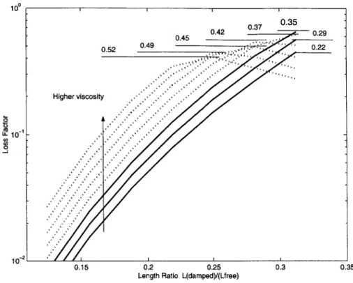
4-4 Loss Factor as a function of length ratio, for different viscosities . . . 46
4-5 Loss Factor as a function of viscosity and length ratio . . . . 47
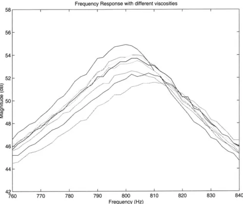
4-6 Frequency Response with different viscosities . . . . 54
4-7 Damping as a function of viscosity . . . . 54
5-1 New Collet . . . .. . .. .. . . .. 57
5-2 Collet Assembly . . . . . .. . .. . . 58
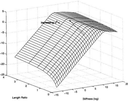
5-4 Variation of w2rq for Cantilever case, as a function of Length ratio and
Stiffness . . . . 61
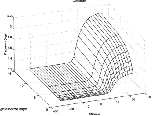
5-5 Cantilever case: Frequency as a function of Length ratio and Stiffness 62 5-6 Cantilever case: w as a function of Length ratio and Stiffness . . . . 63
5-7 Model A: Viscoelastic material behind the second fixed point . . . . . 64
5-8 Variation of w 2 for Model A(Visco all the way to the back), as a function of Length ratio and Stiffness . . . . 65
5-9 Model A: w 2 as a function of the length ratio and stiffness . . . . 66
5-10 Model A: Viscoelastic behind the second fixed point . . . . 67
5-11 Model B: Viscoelastic material, only between fixed points . . . . 68
5-12 Variation of W227 for Model B (visco between fixed points), as a function of Length ratio and Stiffness . . . . 69
5-13 Model B: w 2 as a function of the length ratio and stiffness . . . . 70
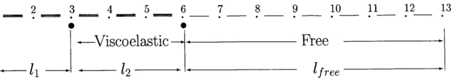
5-14 Shape functions for viscoelastic between nodes 3 and 4, with zero and infinite stiffness . . . . 71
5-15 Final Model: Fixed point in the back-Viscoelastic material only at the front . . . . 72
5-16 Variation of w 2 j for the final design, as a function of Legth ratio and Stiffness . . . . 73
5-17 Final Model:w 2 as a function of the length ratio and stiffness . . . . 74
5-18 Comparison of maximum damping for each model . . . . 75
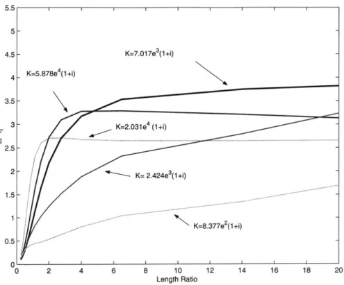
5-19 Comparison of maximum loss factors . . . . 76
5-20 Model for deflection-force calculation . . . . 77
5-21 Force analysis . . . . 78
5-22 Belleville Spring . . . . 79
5-23 Comparison of Frequency response for new collet design and the regural R oyal R 8 . . . . 80
5-24 Comparison of frequency response for second prototype and the regural R oyal R 8 . . . . 81
5-26 New R8 . . . .8 6-1 The Gun-Drill ... ... 84
6-2 Steel Clamps Assembly . . . . 86 6-3 Frequency response using the steel clamps, with the gundrill pinned . 89
6-4 Time response variation from no adjustment(top) to steel clamps(middle)
and steel clamps tightened (bottom) , with the gundrill pinned . . . . 90
6-5 Collar Ring Assembly . . . . 92 6-6 Frequency response of gundrill pinned using the Collar Ring . . . . . 94
6-7 Frequency response of gundrill free, using the Collar Ring . . . . 95
List of Tables
4.1 V iscosities used . . . . 52
5.1 M odel Results . . . . 68
5.2 Belleville Spring Characteristics . . . . 72
5.3 Belleville Springs measured expansion . . . . 73
5.4 First Prototype Data . . . . 77
5.5 Second Prototype Data . . . . 79
6.1 Comparison of the modes measured to the modes of a cantilever beam 85 6.2 Damping and Frequency with and without viscoelastic . . . . 88
6.3 Damping and Frequency for gundrill-pinned . . . . 94
Chapter 1
Introduction
1.1
High Speed Machining
Metal removal rates are faster today than ever before. What was considered high speed machining just a few years ago is regarded as conventional today. Many factors are driving shops to faster metal cutting rates and higher rates of productivity. The need to put more work across machine tools has shops looking constantly to improve metal cutting processes. As a result, cost effective, agile and high quality production are three major issues in high speed manufacturing. The demand for higher part surface quality and metal removal rates have lead to the slow but continuous increase
of spindle speeds in high speed machining.
As a result of the continuous effort in this area, it is expected that high speed machining will show considerable growth in the coming years. Machine tool indus-tries will have to develop products that will be able to satisfy the higher customer expectations for faster cutting speeds and better cutting performance. These include better and more capable machine tools and CNC processors that allow the machine to accurately cut at increasingly higher speeds and feeds.
1.2
Why Higher Speed?
Implementing higher speed machining in a shop has many benefits, some obvious but others less so. Obviously, making parts faster helps satisfy customers' demands for quicker deliveries despite shorter lead times. Applications such as rapid prototyping and mold making, in which smooth surface finishes, complicated geometries and fast cycle times are required, take advantage of the benefits of high speed machining. There are also benefits derived from increased tool life. It may seem paradoxical, but machining at high speed with the right tooling matched to the application can reduce tool wear because of the diminished cutting forces at high speed.
The decrease of cutting forces at very high speeds can help a shop manufacture more accurate parts with better surface finishes. A less obvious benefit of high speed machining for shops moving in that direction is derived from the exercise of imple-menting it. Learning to do the things necessary for successful high speed machining can simultaneously elevate other facets of an enterprise to equivalent levels of pro-ductivity.
The major improvement is due to the reduction of cutting forces in the increased number of tooth passes to remove a given amount of material. Much of the chip formation mechanics at high speed involve heat. At high speeds, most of the heat generated in deformation cannot diffuse away from the shear zone. Higher tempera-ture at the primary shear zone helps speed up the plastic deformation process that results in a chip being formed. Because of the increased rate of plastic flow, high speed cutting experiences a decrease in the cutting force needed to remove a chip.
Apart from the need for high speed machining, the major driving force for this project is the need for deep cavity machining. Conventional toolholders do not provide the required stiffness and damping characteristics for deep cavity machining. Small tool radii and long cutter bodies are needed to access these surfaces. As a result, due to the increased tool overhang, cutting force variation is initiated when these kind of tools are used.
1.3
The Main Problem
The main problem in deep cavity machining is the initiation of chatter when modes of vibration of the cutting tool are excited. Chatter is manifested by strong vibration between the cutting tool and the workpiece. It can result in poor surface finish and accelerated tool wear. Extensive research has been performed in the recent years to the problems of chatter in machining and measures of stability improvements have been explored. The main reason for chatter occurence is low damping in the machine tool system which leaves a major part of the transmitted energy unabsorbed.
Most of the solutions available for chatter supression do not account for economic issues. As the need for high speed machining increases, low cost and effective solutions are sought.
This research project aims at developping effective methods to improve current toolholding mechanisms and to increase damping in long overhang tools. A complete redesign of the widely used R8 collet is performed. The goal is to achieve stiffer positioning of the collet in the spindle and of the tool in the collet, through the use of a second hard point in the back, and higher damping through the use of viscoelastic material. Finite element models are developped to examine the different available configurations and to measure the damping effect in each one. Cutting tests are performed to qualitetively determine the improvement in surface finish.
Two types of tools are examined: a viscous-damped tool (of the type developped
by Rohatgi, 1999) where energy is dissipated in a thin layer of viscous fluid that
surrounds the tool shank, a viscoelastically damped tool. Finite-element modelling provides insight on the dynamic behavior of the tools. Modal analysis is performed to determine their dynamic behavior and measure the increase in damping. In both cases the increase in damping is substantial.
Before presenting the research part of the project, it is useful to provide the basic background on the types of machine tool vibration, the currently available methods for chatter reduction and the theory behind damping.
Chapter 2
Types of Machine Tool Vibration
Machine Tools are subject to three types of vibration: free, forced and self excited vibrations. Free vibrations occur when the stable system is displaced from its equi-librium position and allowed to vibrate freely. In this case the system will vibrate and evenually return to its original position in a manner dictated by it structural characteristics.
When a dynamic exciting force is applied to the system, forced vibration occurs. These forces are commonly induced by one of the following three sources:
1. Alternating cutting forces such as those induced by inhomogeneities in the
work-piece material (hard spots, cast surfaces, etc), cutting forces periodically varying due to changes in the chip cross section.
2. Internal sources of vibrations, such as disturbances in the workpiece and cutting tool drives (caused by worn components, defects in gears, instability of the spindle,etc), out of balance forces (masses in the spindle or transmission).
3. External disturbances transmitted by the machine foundation
Self-excited vibration or chatter is initiated by variations in the cutting forces
(caused by changes in the cutting velocity or chip cross section), built-up edge, and regenerative effects.
Chatter depends on the design and configuration of both the machine and tooling structures, on workpiece and cutting tool materials, and on machining regimes. The stiffness of the tool, spindle, workpiece and fixture are very important factors. The cutting stiffness of the workpiece material is also an important factor; for example steel has a greater tendency than aluminum to chatter. The chatter resistance of a machine tool is often expressed in terms of the maximum allowable width of cut bum.
2.1
Chatter occurence and suppression
Forced vibration may be easily identified during the development stage or final in-spection of a machine tool and can be easily reduced or eliminated. On the other hand, chatter occurence may not be easily detected during the runoff stage, unless the machine tool is thoroughly tested. In addition, since it is typically a nonlinear phenomenon, chatter may occur only under specific cutting conditions and may ap-pear sporadically. As a result, the elimination of chatter in a particular machining process can be very tedious and can be accomplished only by reducing the produc-tion rate. The predicproduc-tion of chatter and the determinaproduc-tion of stability involves the understanding of:
a. The dynamic structural response characteristics of the system
b. The cutting stiffness, cutting force, and chip thickness.
Finite element analysis (FEA) and dynamic testing are used to study the vibration and chatter problems during.the design stage and runoff of equipment.
As mentioned before, chatter initiation is due to the fact that the damping of the machine tool system is not sufficient to absorb the portion of the cutting energy transmitted to the system. The practical significance of the chatter depends on the type of operation, whether it is a finishing or roughing operation, the surface finish requirements, and tool wear characteristics. Chatter becomes more significant as cutting speeds increase since the forces excited approach the natural frequencies of the system. It is often difficult to overcome chatter, but progress can be made through the proper selection of cutting conditions, better design of the machine tool structure
and spindle, and improved vibration isolation.
Chatter suppression typically referrs to increasing the machining process stability. In practice the stability problem (chatter suppression) and the surface finish prob-lem are coupled because the occurence of vibration and especially chatter reduces machined surface quality.
Two approaches may be taken to solving chatter problems. The first is to choose or change cutting conditions such as the cutting speed, feed, tool geomatry, ,etc, to optimize the metal removal rate, while operating in a stable regime. The second is to analyze the dynamic characteristics of the machining system to determine the stable operating range, and suggest improvements to the system design which can extend this range(Tlusty, 1985).
2.1.1
Self-Excited Vibration (Chatter)
Self-excited vibration occurs because the dynamic cutting process forms a closed-loop system. Disturbances in the system are fed back into the system and may result in instability. Self-excited vibrations do not result directlly from external forces, but draw energy from the cutting process itself.
The characteristic features of self-excited vibrations are:
1. The amplitude increases with time, until a stable limiting value is attained
2. The frequency of vibration equals a natural frequency of the system
3. The energy supporting the vibration is obtained from an internal source.
When the dynamic cutting force is out of phase with the instantaneous relative movement between the tool and the workpiece, this leads to the development of self-excited vibration. This type of instability is called regenerative chatter because the vibration reproduces itself in subsequent revolutions through the generation of the waviness. A second type of self-excited vibration is the nonregenerative chatter which occurs without undulation.
2.1.2
Regenerative Chatter
In this section, we provide an overview of the theory of regenerative chatter following teh presentation by Tlusty(, 1985). The dynamic machining process can be repre-sented as a closed loop system by the block diagram in the figure below.
CUTTING PROCESS
MACHINE TOOL STRUCTURE
Figure 2-1: Closed loop system of machine tool structure and cutting process
Dynamic fluctuations of the cutting force and tool position relative to the work-piece occur in all machining processes because workwork-piece and tool are not infinitely stiff. This relative motion leaves an undulation of amplitude yi on the machined surface. Tlusty (1985) performed a simple analysis that assumes that the dynamic cutting force is proportional to the undeformed chip thickness. The vibration of the tool in the direction normal to the cut surface during the ith cut is:
yj = Y sin(wt) = Xi cos(a) sin(wt) (2.1)
The direction of the principal vibration X in the figure below, forms an angle a with the normal to the machines surface Y. The chip thickness variation due to the surface wave Yj_1 produced by subsequent cuts depends on the phase lag E with the
surface wave Y left by the previous revolution. The number of waves between cuts is:
E
f
n + - - (2.2)
27r N
where nr is the largest possible integer (number of whole waves) such that E/27r < 1 and E is the phase of inner modulation yj to the outer modulation yi-1. The maximum chip thickness variation occurs at c = 180'.
Based on the regenerative chatter theory, the state of the dynamic cutting process is described by:
>1 unstable
= =1 at stability limit (2.3)
Yi-1
I <1 stable
The relationship between the amplitudes for the ith and (i - 1)th cuts is:
Yi Xi -G(w)
(2.4) Yi-1 Xi-1 G(w) + 1/kdb
Regenerative instability wil occur when the vibratory motion increases with time, in which case the magnitude of the above equation is greater than 1 for some fre-quencies. The stability limit is obtained when the magnitude of yi/yi_1 is set to 1
-1
ImG(w) = 0 and ReG(w)= (2.5)
2kd b
where kd is the specific dynamic stiffness, which is assumed to be a material constant. Therefore, the limit width of cut is given by:
bum = -1 (2.6)
2kdRe[G(w)]
However, if the phase shift E (eq 2.2) is left free to accept any value, then equation
2.6 does not determine a specific value of bum and chatter may occur at various
frequencies, resulting in many values of bum(King, 1985). One of them is the minimun value that represents the limit of stability:
-1
(blim)min = 2 (2.7)
2 kdRe[G (w) ]m,,
In order to illustrate all this. let us consider the system depicted in figure 2-2. The systems vibrates in the X direction, has damping c and stiffness k and the tool has
mass m. The direct transfer function of this system, denoted as Gd is the ratio of the vibration in X over the component of force F acting in the direction X, F , between the tool and the workpiece.
x
Too I
F
Yi
WORKP IECE
Figure 2-2: Regenerative Chatter due to the cutting of an undulated surface
We have that:
X(w) 1/kw2
Ga =n F-(w) w2 2+ 2jww(8 (2.8)
where wn is the natural frequency of the system:
k
- k (2.9)
m
and the damping ratio ( is:
c
(2.10) 2 Vdm
The minimum Gd,min, i.e. the maximum negative point of ReG is given by: -1
Re(Gd) = (2.11) 4k(1()
at Wmin = wn(1 + ().
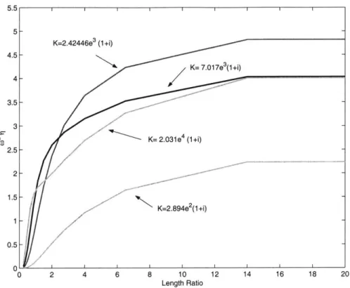
When interpreting the model results, we want to get a feel of how bum behaves and how it is related to the damping and stiffness of the system. To achieve this we know that Re(G) depends on the product k(, and that ( is analogous to the loss factor rq. From equation 2.9 we see that W2 is analogous to the stiffness k. Putting
everything together, gives us the term w r, which incorporates both the stiffness and the damping characteristics of the system. The goal in each of the designs presented is to maximize this factor, and therefore achieving maximum damping at the highest stiffness.
To help understand how vibration at the tool tip can lead to chatter, the process of self-excitation and regenerative chatter is represented by the block diagram of the closed loop system shown in the figure below. Under certain conditions, the next pass of the vibrating tool can align with the rough surface just cut (yi-i) to cause variations in the chip thickness (regenerative feedback).
2.1.3
The Negative Effects of Chatter
1. Low quality parts:The vibrations that result in chatter cause the cutting tool tip to entirely lose contact with the workpiece, and then dig deep in it. Apart from the high pitched noise that is generated, this results in poor surface quality since the depth of cut deviates from the required tolerance limits. In some cases this may lead to damage of the part.
2. Increased spindle wear:
Most of the commonly used machine tools are not designed for high ampli-tude vibrations on a continuous basis. Chatter can result in damage of the spindle and linear axis bearing surfaces, which result in early failure and high depreciation costs.
3. Increased tool wear:
As a result of the impact between the tool and the workpiece, the cutting tool is also damaged which results in early tool wear. This leads to increase of the tool change rate and tool consumption costs.
4. Lower output:
in the amount of vibration during operation must be obtained. The simplest way to attain this is to decrease the metal removal rates. This leads to an increase in the machining time required for each part.
As a result of the longer machining time, the manufacturing costs rise, causing an increase in the selling price of the product. This may very easily cause reduced revenues and market share, which hurt the state of the business and any considerations for future projects. Consequently the manufacturer will have to reduce profits by chosing a smaller margin to maintain a target selling price.
2.2
Available Methods for Chatter Reduction
Most of the universal available methods available for chatter reduction do not modify the machine tool structure in any way and have limited applicability.
1. Damping materials:
Machinists can effectively dampen the machine tool system through the use of visco-elastic materials, mounted on certain components of the system. However, eliminating the problematic mode is usually a harder task.
2. Reducing tool overhang:
The amplitude of vibration can be reduced as the overhang length decreases due to the increased tool stiffness. At conventional speeds the input force spectrum is dominated by low frequencies. In this case, the static compliance of the system dominates the system's response, rather than the resonant peak response of its natural modal frequencies.
Although minimizing tool overhang may seem like the obvious thing to do, its implications are very important. The overall length between the spindle gauge line and the tool tip should be kept to a minimum for a number of reasons. Stiffness drops quickly as tool length increases. The bending and torsional stifness of a cylindrical beam are:
Kbending L (2.12)
Ktorsion ~ (2.13)
where D and L are the beams diameter and length respectively. As we can see, the longer the tool, the less stiff it will be. So, if for example the length of the tool-holder is doubled, its bending stiffness will drop by a factor of eight, while its torsional stiffness will drop by 50% or more. According to these relation-ships, the increases in tool length can be compensated by using larger diameter tools. However, larger diameters can cause other problems such as introducing imbalance and, most important, restricting clearance to small cavities. An-other negative effect of using long tools is the increased runout, which results in decreased accuracy of parts produced, induced vibration and accelerated tool wear.
3. Reducing the cutting tool rake angle:
By reducing the rake angle, i.e. the angle of inclination between the leading
edge of the cutting tool and the part being cut, smaller reaction forces are generated when a chip is sheared from the workpiece. Also the variations in cutting force for a given amplitude of vibration decrease with smaller rake angle. As a consequence, it is general practice to grind tools to small rake angles. 4. Radiusing the tool:
A radiused tool does not penetrate the workpiece as readily as a sharp point.
Thus, the deflection at the tool tip for given variation of the cutting force, and thereby the stored energy in the cantilever tool that causes chatter, is reduced.
2.2.1
Products for chatter reduction
In the case where the universal approaches to chatter reduction are not sufficient, certain products are available to increase the machine tool system's resistance to
chatter. However, most of these solutions have high purchase and implementation costs associated with them. A machine tool designed for high speed machining
requires not only a high speed spindle, but the capability of operating at high feed rates with high accuracy. The build up of inaccuracy in the machine tool socket and the toolholder taper results in radial eccentricity (runout) of any spindle mounted tool, the magnitude of which will also depend on the tool length. High runout at high rotational speed will lead to unbalance, vibration, reduced tool life and poor surface finish.
Several toolholder designs provide taper/face contact. All of them are more ex-pensive than the conventional ISO taper, and require new spindles, since they are not compatible with the standard 7/24 toolholders.
Conventional Tool holder (ISO Taper)
Tapered tool holders are located in the spindle through the mating of two tapers. The standard 7/24 tool/spindle interface is dimensioned so that there is a guaran-teed clearance between the face of the spindle and the toolholder flange. The main advantage of the 7/24 taper connection is that it is not self-locking and is secured by tightening the toolholder taper in the tapered hole of the spindle, thus allowing fast connections and disconnections. Another advantage is its simple design, requiring only one dimension, the taper angle, to be machined with a high degree of preci-sion. As a result, the majority of machining center spindles and the spindles of many other machine tools have 7/24 tapered holes, and there is a huge inventory of such toolholders.
However, the conventional taper interface has many serious shortcomings. It is not ideal when used at high rotational speeds, even when a high tolerance taper is specified. A number of disadvantages are: large mass and size, lack of rigidity of the machine tool socket, which may distort under high centrifugal forces at high rotational speeds, and poor repeatability at tool changing. The 7/24 taper must satisfy two parameters simultaneously: precision location of the toolholder relative to the spindle, and clamping for adequate rigidity to the connection. Radial location
is not adequate since standard tolerances result in clearance between the back part of the taper and the spindle hole. Moreover, the absence of face contact between toolholder and spindle leads to micro motions between the male and female tapers within the clearance, and thus to fretting and wear of the spindle at high cutting forces.
Stiffness and accuracy of axial positioning are especially important for high speed spindles. As spindle speed increases, the spindle shaft tends to expand due to the centrifugal force and thermal effects. This causes the tapered tool holder to be drawn further into the spindle due to the retention force applied by the drawbar (Arnone, Miles, 1998). Thus, the stiffness of the interface between the tool and the spindle is reduced, making the steep tapered too holders more susceptible to chatter. The lower stiffness limits the use of aggressive cutting parameters, and increases the in-accuracy when working with longer tools. Expansion of the spindle may also lead to deterioration of the toolholder balance.
HSK
The HSK interface system (DIN 69893)is the most recent design, jointly developped
by German machine-tool builders, cutting tool manufacturers (including Guhring)
and end users. It is retained in the spindle by use of grippers that sit inside a hollow cup behind the gauge line of the tooling (see picture). It uses 1:10 taper, is short in comparison with the 7/24 taper , and has a thin-walled design. As a result, the application of high axial force causes simultaneous contact between the taper and face surfaces, partly due to the shrinking of the taper (Toolholder/Spindle interfaces for CNC Machine Tools). With increasing spindle speed, centrifugal forces cause the grippers to expand within the toolholder, pressing it tightly up against the interior of the spindle shaft. This results in greater stiffness in the interface. The system operates with a modified drawbar that connects to the taper through a wedge-like connection, which applies higher load at increasing cutting speeds.
The increased stiffness of the HSK tooling system provides a higher degree of accuracy, compared to the conventional toolholder. When drawn into the spindle, it
provides a simultaneous fit on both the spindle nose (via a flange) and the spindle taper. This insures high repeatability when inserted and removed from the spindle.
Although HSK has many benefits, there are some major disadvantages associated with it. Testing has indicated that the small size HSK systems are more susceptible to chatter than the ISO taper tooling. This is probably due to the longer extension from the gauge line required to support a given tool length when using HSK, since the hollow cup behind the gauge line does not allow using collets or other clamping mechanisms. In contrast with the ISO taper, where tooling can be placed partially behind the gauge line in the body of the taper itself, in HSK tooling collets must reside entirely in front of the gauge line. This increases the effective length of the tool assembly, which results in decreased stiffness, since stiffness in bending decreases as the cube of the length and increases with the diameter to the fourth power (Arnone, Miles, 1998). When larger HSK toolholders are used, the diameter of the holder body grows so that its stiffness overcomes the adverse effects of the longer overall length.
3EI
kT=L
64
One of the principal drawbacks encountered during the adoption of the HSK system is its sensitivity to the presence of chips or contaminants. Lack of proper cleaning can result in the presence of chips in the spindle nose, which prevents the HSK toolholder from being located properly in the spindle.
As mentioned before, the HSK toolholder is not compatible with existing spin-dles and toolholders. Its high fabrication accuracy and intricate design make HSK spindles and toolholders very expensive (toolholders are 1.5-2 times more expensive than 7/24s). The drawbar is also more complicated and expensive, since it needs a mechanism for kicking out the toolholder (the 1:10 taper self locks in the spindle).
Heat Shrink Tool Holding
The concept of induction heating the cutting tool and shrink-fitting into a conven-tional holder was recently introduced to industry. In this case the toolholder is com-pletely solid, with a precision bore to accept the tool. At room temperature, the holder bore is smaller than the tool shank diameter that it will accept. The tool-holder is then heated using an induction heater, causing it to expand, which allows the tool to be inserted in it. As the holder cools, very high pressures are exerted to the tool, clamping it tightly in place.
Heat-shrink tool holders provide excellent results in toolholding rigidity and ma-chining quality. The concentricity of this system is consistently 0.0002 in., or better. Heat shrink toolholders can be perfectly symmetric. No set screws are needed to clamp the tool, making it possible to manufacture them to a very low level of imbal-ance. Balance pockets are machined in the drive keys on all V-Flange tooling elim-inating the imbalance inherent in the V-Flange design (R.C. Dewes, D.K.Aspinwall, M.L.H.Wise, 1994). This results in balanced chip loads, better finishes, and increased speeds and feed rates.
Another advantage is that the shank of the tool is gripped over its entire circum-ference along the length of the bore. This is not the case with milling chucks and hydraulic chucks which leave an area of up to 0.25 in from the end of the toolholder with no force applied to the tool. Due to its extreme rigidity and stiffness, the heat-shrink system has proved to extend tool life. It is also a simple and fast method of changing reclamping tooling. The average induction cycle takes seven seconds to expand the bore, letting the operator remove the dull tool and insert the new tool. Since the induction system localizes the heat to the clamping area only, a cycle time of less than 10 sec minimizes conduction of heat through the toolholder. The entire process takes less than 30 sec.
The performance of the heat-shrink tool holder depends greatly upon the accuracy of the tool shank and the operating temperature during machining. Since thermal contraction is used to secure the tools, further sensitivity to elevated operating
tem-peratures should be expected. As temtem-peratures increase, the amount of clamping pressure can decrease.
Hydraulic Toolholders
While these type of toolholders have been available for a long time, only in the last few years have they become as high quality and low maintenance as they are today. Hydraulic toolholders use steel's ability to stretch and compress within its elastic limit without failure for thousands of times. An oil chamber surrounds an expansion sleeve, and a set screw is turned to force the piston and seal against the hydraulic fluid (see figure). This forces the fluid into the chamber, compressing the expansion sleeve under extremely high pressure (around 20,000 psi). The pressure distributes evenly over the entire circumference, so that the sleeve expands evenly and concentrically over its length around the tool shaft. The uniform pressure clamps the tool, and full contact is achieved over the length of the engagement. Releasing the hydraulic pressure with a turn of the screw returns the sleeve to its original size.
Hydraulic toolholding minimizes runout of the tool relative to the toolholder. Tests showed a runout of less than 0.00012" TIR measured a distance two and a half times the cutter diameter from the end of the holder (Arnone, Miles, 1998) . Thus a more uniform chip load on the cutting tool is achieved, which extends tool life and improves surface finish. In comparison, the best conventional collets will provide a runout of approximately 0.0003" TIR, while less accurate collet designs exhibit runout values of 0.0005" at the toolholder nose. Some concentricity is lost when intermediate slotted sleeves are used between the tool and the expansion chuck. Overall, the combination of accuracy and stiffness obtained with hydraulic toolholders cannot be matched by conventional means.
Vibration damping in these toolholders comes from the hydraulic fluid within the chuck acting as a natural dampening agent and impact cushion. The damping con-tributes to longer tool life and improved surface finish. Tool life may go up three or four times over less precise mechanical holders, according to hydraulic chuck man-ufacturers. The damping effect of the clamping system prevents microcracking of
the tool cutting edge caused by vibration, which is present in a mechanical clamping system. The lack of runout makes the tool cut more evenly, which means less wear.
The principal drawback of hydraulic toolholders is their cost. A CAT40 expansion chuck can cost as much as five times more than a conventional chuck. This difference in cost makes it not practical for most shops to exclusively use hydraulic toolhold-ers. In difficult, though, machining operations such as hard die milling, where the cutters are highly susceptible to breaking due to unbalanced cutting loads, hydraulic toolholders are recommended for use in all process steps for optimal results.
Chapter 3
Theory and Model Implementation
Damping is usually determined under conditions of cyclic oscillations. Thus we take
x = X sin(wt -
#)
for the steady state displacement and ± = wX cos(wt -#)
forthe steady state velocity. Depending on the type of damping present, the force-displacement curve may differ greatly. In all cases however the force-force-displacement curve will enclose an area, referred to as the hysteresis loop, that is proportional to the energy dissipated per cycle due to the damping force Fd. The energy dissipated is given by:
Wd = fFddx (3.1)
In the case of a spring-mass system with viscous damping, the damping force is given
by Fd = cz. Using the relations w,, = k/m and c = 2(/kn we have:
Wd = 2(7rkX 2 (3.2)
where ( is the damping ratio of the system. One of the most commonly used measures of damping is the loss factor 71 defined as the ratio of the energy loss per radian Wd/27 divided by the peak potential or strain energy U:
Wd
3.1
Comparison of viscous and hysteretic damping
3.1.1
Viscous Damping
Consider the simple oscillator shown in figure 4-1, consisting of a mass M attached to a spring with stiffness K, with damping being represented classically by a viscous dashpot, so that the damping is proportional to velocity. With an excitation force
F(t) applied to the mass, the system will respond with a displacement x(t), considered
positive in the upward direction.
M
K
C
Figure 3-1: Single degree of freedom system with viscous damping
Applying force balance using Newton's second law, and letting the excitation force be a steady harmonic function F(t) = Fcos(wt) yields the differential equation:
Mx(t) + Cx(t) + Kx(t) = Fcos(wt) (3.4)
The complementary solution of this equation is of the form:
xc = e-(,,nt(Cl sin(wdt) + C2 cos(wAt)) (3.5)
and the damped natural frequency Wd of the system is wd -
(
This is thetransient response of the system, which consists of oscillation at the damped natural frequency whose amplitude decays as e-Cwnt. A particular solution x, of equation 4.5
is any function x(t) that satisfies the equation. We have that: Fcos(wt - .) = (K - Mw2)2 + w2C2 where q$=tan-l[ W (3.7) (K - MW2)
So, the complete solution of equation 4.5 is:
x = xC + x, = e -t(Cisin(wdt) + C2cos(wdt)) + Acos(wt - #) (3.8)
with
A= F
A = (3.9)
(K- Mw2)2 + w2C2
In other words, the response of this single degree of freedom system is the sum of a transient oscillation with natural frequency Wd and amplitude that depends on initial conditions and decays over time, and a steady state oscillation at the frequency w of the exciting force and a phase angle 0 lagging the excitation. If the damping is larger, the transient response quickly dies away. The steady state response, however, remains for as long as the excitation is present and provides insight into the system behavior when a harmonically varying force is applied to the resonant structure. As the frequency increases, the inertia term -Mw2x steadily becomes larger until it is equal to the stiffness Kx. At that point resonance occurs, and the stiffness and inertia forces cancel out, leaving damping as the only was to limit the amplitude of vibration(Ahid D. Nashif, David I.G. Jones, John 0. Henderson, 1985). At frequencies far above resonance the inertia term dominates and the response becomes very small, and is out of phase with the excitation (0 ~_ 180'). At low frequencies of
excitation the motion of the system is dominated by the stiffness K, and the response of the mass is in phase with the excitation (# c 0). Three important frequencies can be identified for the viscous case:
1. The undamped natural frequency wn = K/M, by setting C = 0 in equation
2. The damped natural frequency from equation 4.6:
Wd = Wn, 1 - )2 (3.10)
3. The resonant frequency for which I xp/F I is a maximum, from equation 4.8
W, w (1 (2) (3.11)
The energy dissipated per cycle in this system is given by:
Wd =
j
Fddx = 7rCwA2 (3.12)and therefore q = 2(.
3.1.2
Hysteretic Damping
The effect of damping on the steady state response of the system is very important for many engineering problems. Hysteretic damping is often utilized in the calculation of steady response. One of the major advantages of using hysteretic damping is the possibility of utilizing the correspondence principle in complicated elastic analyses, where a complex number can be substituted for the real value of the modulus to ac-count for damping. The principal difference between viscous and hysteretic damping is that for the viscous system the energy dissipated per cycle depends linearly on the frequency of oscillation, whereas for the hysteretic case it is independent of frequency. Hysteretic damping is only valid for steady harmonic motion.
Now, If we let the viscous damping coefficient of equation 4.7 be
C = K (3.13)
then the particular solution (equation4.7) becomes:
x = XP = Bcos(wt - 4) (3.14) where:
F
B = (3.15)
I F( )
M X
L k:k ( I+ I h)
Figure 3-2: Single degree of freedom system with hysteretic damping
and
4=tan-'[ K (3.16)
(K - MW2)
with xc set to zero. Setting ei(wt-) = cos(wt -
4)
+ i sin(wt - q), we have thatx = Re[Bei(wt-)] , which leads to:
X = Re[Biwe(iWt-)] = iwx (3.17) So, the system can be written in the form:
-w 2Mx + K(1 + iq)x =
F (3.18)
where K* = K (1 +iq) is the complex stiffness of the spring, in which case it represents
both stiffness and damping. Thus the above first degree of freedom system can be
represented using K* = E*S/L , where E* = E(1 + iq) is the complex Young's modulus of the system, q is the loss factor of the spring material, S is the cross sectional area, and L the undeformed length of the spring. E, K and q are assumed to be constant over a limited frequency range. The energy dissipated per cycle in this system is given by:
Wd = 7rKnB2 (3.19)
In order to find the equivalent viscous damping model for a hysteretic system, we have that at the point where w = w, (resonance) the damping forces are equal.
Substituting w. = VK/M in equation 4.15 we have that
rq = 2( (3.20)
3.2
Finite Element Method
The equations of motion for the tool system can be discretized to yield the following matrix form:
[M]X + [C]X + [K]X = F (3.21)
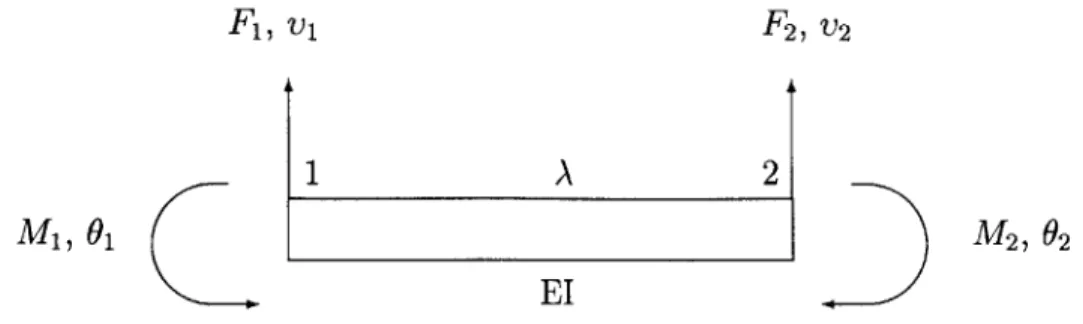
where [M] is the mass matrix, [C] is the damping matrix, [K] is the stiffness matrix and F is the vector of the input forces corresponding to the degrees of freedom of X. The finite element method is used to formulate the mass, damping and stiffness matrix. We employ Euler beam elements to model the dynamic behavior of the tool and sleeve. One-dimensional Euler beam elements have 4 degrees of freedom: each of the element's two ends or nodes has a lateral displacement v and a rotation 0, resulting in four coordinates, v1, v2, 01, 02. The stiffness matrix as well as the mass
matrix can be obtained from the potential and kinetic energy, provided the shape functions of the beam are known.
F1, vi
M 1, 1
1 A 2
M
2, 02EI
Figure 3-3: Positive sense of beam displacements and forces We express the deflection as:
v(x) = Pi + P2 + P3 2 + P4
where = x/l and pi = constants.
Differentiating the slope equation gives:
10(x) = P2 + 2p3 + p4 2
The boundary conditions can be expressed in the following matrix equation:
V1 1 0
191 0 1
V2 1 1
102 0 1
Substituting pi = v, and P2 = 101, we can p3 and p4. Then the desired inverse matrix
Pi 1 0 Pi 0 1 P2 -3 -2 P2 2 1 0 0 Pi 0 0 Pi 1 1 P2 2 3 P2
solve the last becomes: 0 0 3 -2 0 0 -1 1 (3.24)
two rows of the matrix for
VI
101 V2 102
(3.25)
This equation can be used to determine the pi corresponding to the case where each of the displacements is equal to unity, while all others are equal to zero(Thompson,
1986). For example, when v1(x) = 1,with all other displacements equal to zero, the
first column gives :
(3.22)
(3.23) F2, V2
Pi = 1, P2 = 0, P3 = -2, P4 = 2
Substituting into the deflection equation gives the shape function of the firstmode:
01(x) = 1 - 3 2 + 2 3 (3.26)
In the same manner we obtain the following beam shape functions:
#1(x) 02(x) q3(x) #4(x) = 1-3 2 + 2 3 = l - 21 2 + l3 = 3 22 3 =-W( + W(3 (3.27) (3.28) (3.29) (3.30) By considering the displacement in general to be the superposition of the four
shape functions we have:
y(x) =
#
1V1+ 0201 + 03v2+#
402 = q$1q1+ q2 2 +#3q1
+#
4q4 (3.31)where qi are the end displacements.
3.2.1
Tool and Sleeve Mass element [M]ei
To determine the generalized mass, the preceding equation is substituted into the kinetic energy equation:
T = IJy2 mdx =
1
2-
Zj~d
#J
#
f mdx = I miEE i dj2 iij
Thus the generalized mass mij, which forms the elements of the mass matrix, is equal to
(3.33) m j =
#5oq$j~
mdxThe nodal displecement vector of an element Xl is given by:
X 1T = [vI 01 v2 02 ]
The element mass matrix for the uniform beam element is given by:
FMl
- pA 420 156 221 54 -131 412 131 -3l2 156 -221 412where 1 is the element length, A is the cross sectional area and p is the material density. The Global mass matrix can be assembled by superimposing the element
stiffness matrix,as shown below for the case when three elements are used.
[M]e
[ I
Figure 3-4: Assembling the system mass matrix from the individual element mass matrices
3.2.2
Tool and Sleeve Stiffness element [K]ei
The nodal displacement vector of an element Xl is given by
Xe1T = [vI 01 V2 62 1
The element stiffness matrix is given by
El [K~el =---12 61 -61 212 12 -61 412 12 61 412
where I is the element length and I is the cross sectional moment of inertia of a solid circular beam, given as a function of the beam's diameter
(3.34)
rD4
64
The Global stiffness matrix can be assembled by superimposing the element stiffness matrix as shown below.
[Ke =
[K]=
I
Figure 3-5: Assembling the system stiffness matrix from the individual element stiff-ness matrices
3.2.3
Tool and Sleeve Damping element [C]ej
The nodal displecement vector of an element K1 is given by:
XeT = [V1 01 V2 02]
The element damping matrix is given by:
[C]e = Coefficient
156 221 54
412 131
156
where the coefficient depends on whether viscoelastic material is used, or damping is imposed through viscous fluid. In the latter case, the system has to be converted into a first order system. The Global damping matrix can be assembled by superimposing the element stiffenss matrix as shown below for the case when three elements are used.
-131
-312
-221
[C] =
Figure 3-6: Assembling the system damping matrix from the individual element mass matrices
3.2.4
Boundary Condition Adjustment
In modelling the dynamic behavior of a long overhang tool, the tool nodes held in the collet or toolholder are regarded as fixed or ground. Therefore all 4 degrees of freedom at the grounded nodes are set to zero. The deflection at the tool tip is mostly determined by the tool flexibility and only slightly affected by the preload of the tool holder. Grounding a node is reflected by cancelling the corresponding two rows and columns in the system stiffness, mass, and damping matrices.
3.3
Model Implementation
In order for it to be used as a helpful design tool, the model has to be flexible, com-patible with PC hardware commonly available in today's engineering environment, and cost very little to set-up and run. Thus, modelling of the designs involving both viscous fluid and viscoelastic material, was done using MATLAB (Mathworks, 1999). Frequency-domain analysis allows the designer to generate a complete frequency re-sponse for each tool design by evaluating the system behavior at different frequen-cies. Together with an eigenvalue and frequency-domain analysis enable the designer to compare the static and dynamic stiffness of various designs by easily finding the natural frequency corresponding to the first mode of vibration and then accurately determining the amplitude of the response at that frequency. Using the MATLAM
Script, the designer can code automated loops that vary various design parameters in increments and find the system's optimal output performance. MATLAB is avail-able at relatively low cost compared to more sophisticated analysis software such as
ANSYS and COSMOS. Although these software packages are easier to set up, they
do not allow for automated adjust-and-search parameter optimization. Also, due to the generality of the underlying code, they require more processing time to evaluate the performance of each design.
With this formulation, the MATLAB functions returning the natural frequencies and loss factor qj of the tool system can be applied to the various designs. A sample of the code used to model the cases where either viscoelastic material or viscous fluid are used as the damping media, are included in Appendix A.
3.4
Dynamic Response Measurement
Impact tests are a relatively simple way to measure the dynamic response of a machine tool structure. Reducing the amplitude of the force-to-deflection transfer function of the structure should, according to metal cutting theory, increase the stable operating range of metal removal.
During these experiments, the transfer function (ratio of magnitude of output deflection to the magnitude of the input force) is measured using the HP 3567A Signal analyzer over the frequency span of interest. The force is applied using a modally tuned hammer (PC13), while the deflection is measured using an accelerom-eter (PB14) mounted at the tool tip. The hammer produces a voltage proportional to the force applied at the surface. The deflection output is measured by a single axis accelerometer, mounted at the tool tip. The accelerometer produces a voltage signal proportional by Cacc to the acceleration produced at the tip. To deterimne the deflection, the acceleration has to be integrated twice. The deflection amplitude
A(w) is a function of frequency and is calculated from the accelerometer voltage Vacc
A(w) = C2 Vacc (3.35)
with w being the frequency in radians pes second.
Since only the first mode is of interest, the frequency span is set to 800Hz, while a resolution of 800 lines is used, giving a frequency resolution of 1 Hz. The signal ana-lyzer automatically calculates the natural frequency and the corresponding damping ratio associated with the recorded transfer function. Each trial consisted of averaging
10 measurements of the transfer function in order to ensure a smoother and more
ac-curate recording of the tool's dynamic behavior. Apart from the frequency response, the time response is also recorded to ensure that the system behaves as expected, and also to provide insight on how fast the vibration dies off.
3.5
Performance
The performance of the concepts tested is measured by the damping ratio (, which gives a good indication of the damping in the system. The dynamic stiffness of the tool is the inverse of the force to deflection transfer function and is therefore frequency dependent. It is the most important factor in relation to chatter. As a function of static stiffness K, dynamic stiffness Kd can be represented by
Q
= - 1 (3.36)Chapter 4
Fluid Damped Tooling
A squeeze film damped tool, Q - toolTM, (Gaurav Rohatgi, 1998), is used to measure
the damping imposed in relation to the viscosity of the fluid in the damping layer. Several different experimental setups are examined in order to determine the testing conditions that would provide the most effective collection of data. Emphasis is given on the repeatability of data acquisition. The main part of the experiment is performed on a horizontal milling machine.
B 0 14 CLEARANCE 15:1
025. 5
SEAL 1NG R IN
SECTION B-B
-HOLES THROUGH '4HICH DAMPING FLUID !S INJECTED
Figure 4-1: The Q-Tool
According to the results, the highest damping was attained using oil of viscosity (p) 0.28 Nsec/m 2 .