HAL Id: insu-02269767
https://hal-insu.archives-ouvertes.fr/insu-02269767
Submitted on 23 Aug 2019HAL is a multi-disciplinary open access
archive for the deposit and dissemination of sci-entific research documents, whether they are pub-lished or not. The documents may come from teaching and research institutions in France or abroad, or from public or private research centers.
L’archive ouverte pluridisciplinaire HAL, est destinée au dépôt et à la diffusion de documents scientifiques de niveau recherche, publiés ou non, émanant des établissements d’enseignement et de recherche français ou étrangers, des laboratoires publics ou privés.
A Component Driven Development Process From The
System Design To The Final Implementation
G Veran, G. Garcia
To cite this version:
G Veran, G. Garcia. A Component Driven Development Process From The System Design To The Final Implementation. Embedded Real Time Software and Systems (ERTS2008), Jan 2008, toulouse, France. �insu-02269767�
A Component Driven Development Process From The System
Design To The Final Implementation
G. Veran
1, G. Garcia
21: Thales Alenia Space, 100 bld du Midi – BP 99 06156 Cannes La Bocca Cedex France 2: Thales Alenia Space, 100 bld du Midi – BP 99 06156 Cannes La Bocca Cedex France
Abstract: This paper describes a “seamless”
component driven engineering process for control law or mode management software whose algorithms are designed in Simulink/Stateflow. An interface mechanism between this tool and a real-time target allows gathering the components modelling and the components implementation in a unique process flexible and adaptable. The component architecture is preserved during all the development and the closed-loop between the avionics components and the environment is never broken, enabling the developper to perform representative simulation form the first system model until the final implementation.
Keywords: Component, Model, Transformation,
Simulink
1. Introduction
Component driven engineering has been introduced to help managing the increasing complexity of information systems. A component is a block that implements a basic functionality. It is described by its interface, i.e. the services it provides and the services it uses. Recently, the component-based development process has been introduced for real time embedded systems. Real time software often implements complex control laws or mode management algorithms such as AOCS (Attitude and Orbit Control System) for spatial aircraft. Generally these algorithms are developed in two phases. First they are designed with modelling tools like Simulink/Stateflow. Once validated in these tools, the algorithms are coded manually or by automatic code generators and then validated on real hardware. This two-phase process creates a strict separation between the algorithms design and the software implementation. This paper presents a mechanism for interfacing the design tool (Simulink) with real software running on the target. It makes it possible to incrementally implement the component models without breaking the component architecture. By doing so, it improves the development process and enables a fast prototyping on the hardware target.
This paper is organized as follows: In section 2, we present the process. In section 3, we introduce the Simulink/OBSW (On-Board Software) interface
mechanism. In section 4, we present a full use case and the main experimentation results. Finally, in section 5, we summarize the contribution of this paper and point out the future directions of this work.
2. The Component Modelling Process
2.1 The modular architecture
The modular architecture used [1] was designed to improve the reuse of software components and the dynamic modification of on-board software. It is based on a library called framework that contains the basic common functionalities (TC management, TM management, software bus services…). The services offered by this library enable the developer to easily integrate software components into a software bus. This mock-up is based as much as possible on free standard or open technologies (UDP, XML, Python, RPC…). The mock-up is running on a Linux PC host with either a processor simulator or a real target (FPGA or ASIC board) 2.2 Overview of the process
During the first phase of a project, a mission analysis is performed to define the first architecture of the avionic. The components are selected and preliminary versions of the control algorithms are modelled in Simulink. Simulink models are naturally organized in sub models, which can be interpreted as components. Generally, a Simulink model contains:
• Sensor component models • Actuator component models
• OBSW component models which implement the control or mode management algorithms
• The environment model which describes the physical laws that govern the target
Closed-loop simulation is performed between the environment and the avionic architecture (sensors, actuators and OBSW models).
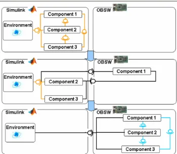
The incremental model transformation process proposed enables the transfer of the components
one by one from the Simulink model to the software architecture. If a component model comes to maturity before the other it can be implemented in software and plugged into the modular avionic architecture while the others components remains in Simulink.
During these transformations, the closed-loop constituted by the components and the environment is never broken. As a consequence, the components code can be easily tested with representative values during all the development steps.
At the end of the process, all the components are implemented in software and only the environment model remains in Simulink. The software
architecture can still being simulated, Simulink computing the input data of the OBSW and the OBSW computing the input data of Simulink. An example of incremental transfer is described in figure 1.
Figure 1: An example of incremental transfer 2.3 Components interface description
With this process, the components can be indifferently implemented as Simulink models or as software code. The component interfaces can be implemented either in Simulink (both components are in Simulink), in software (both components are in OBSW), or thanks to the Simulink/OBSW interface mechanism if one component is in Simulink and the other in OBSW. To keep the avionic architecture constant, the component interfaces are preserved during the transformation process.
The component interfaces (figure 2) are described using the Interface Description Language (IDL [2]). An IDL file is written for each component, describing
in particular the nature (type, name, and frequency) of the signals exchanged by the component.
Spacecraft Ground Operator Environment Startracker AOCS <<interface>> I_STR_acq
getAttitude (out quaternion_t q, out status_t status)
<<interface>>
I_GYRO_acq
getSpeed (out speed_t speed, out status_t status)
<<interface>> I_RCT_cmd setCommand (out cmd_t cmd) RCT Gyro Spacecraft Ground Operator Environment
Startracker AOCSAOCS
<<interface>>
I_STR_acq
getAttitude (out quaternion_t q, out status_t status)
<<interface>>
I_GYRO_acq
getSpeed (out speed_t speed, out status_t status)
<<interface>>
I_GYRO_acq
getSpeed (out speed_t speed, out status_t status)
<<interface>> I_RCT_cmd setCommand (out cmd_t cmd) <<interface>> I_RCT_cmd setCommand (out cmd_t cmd) RCT RCT RCT Gyro Gyro Gyro
Figure 2: Model Interface Specification A set of specific IDL compilers (figure 3) is used to generate automatically the OBSW interfaces and the OBSW skeletons in order to ease the component integration into the generic mock-up. The IDL files are also processed to produce XML files used by the ground software database to encode/decode the TC/TM send or received by the ground operators.
Model2Model - Model2Text Transformations AOCS IDL File Gyro IDL File STR IDL File RCT IDL File Model Python interf. code IDL 2 Simulink IDL 2 Python
IDL 2 Python IDL 2 SwBus IDL 2 XML
Simulink Model SDB input files Ground SDB files Ada files Component skeleton C interface files Simulation Framework Component Python interf. code IDL 2 C Simulink closed loop
Model2Model - Model2Text Transformations AOCS IDL File Gyro IDL File STR IDL File RCT IDL File Model AOCS IDL File Gyro IDL File STR IDL File RCT IDL File Model Python interf. code IDL 2 Simulink IDL 2 Python
IDL 2 Python IDL 2 SwBus IDL 2 XML
Simulink Model SDB input files Ground SDB files Ada files Component skeleton C interface files Simulation Framework Component Python interf. code IDL 2 C Simulink closed loop
Figure 3: Specific IDL Compilers
3. Simulink / On Board Software Interface
3.1 Overview of the Interface Mechanism
The Simulink/OBSW interface mechanism makes it possible to exchange data between a Simulink
model and the OBSW running on the target. This paragraph describes the process of interfacing a component implemented in Simulink with another implemented in the software modular architecture. The first issue is to go out of the Simulink tool. The interface mechanism takes advantage of the fact that Matlab/Simulink tool is written in Java and it is very easy to add dynamically a Java object in Matlab workspace.
A class CptNameInterface.class is written and contains several functions with a prototype similar to the followings:
public Object setValues(float[] values) public double getValues()
This class has a simple constructor with only two parameters (the IP and port of the target). Entering the following command in Matlab shell creates an instance of the class:
CNItf=CptNameInterface('target',port); After that, the object instance is visible in Matlab workspace. The functions provided by this object can now be called from Simulink model by using M-functions blocks. The “Matlab Function” field of the Simulink block is filled with the name of the function to call taking as parameters, first the instance name of the CptNameInterface object and secondly the incoming signal. Due to Simulink restriction, the input signal shall be of double type but can have several dimensions.
Figure 4: Simulink/OBSW Interface Simulink Blocks A component interface block containing a set of the previous Simulink/OBSW interface blocks (cf. figure 5) is designed with the same interface than the original model. The latter can then simply be replaced by its interface block counterparts.
From the Java object, it is easy to send the data through a TCP/IP network to the target. Although a direct connection with the target is possible (if the target provides a TCP or UDP link) we choose to reuse an intermediary XML-RPC [3] server written in Python, which already handle all the communication (TC/TM) between the board and the ground in our architecture. This enables us to have a unified communication mechanism between the target and the ground. We use Java XML-RPC libraries to
connect to the XML-RPC server from the Java and for each component we add to the server a specific class to handle the communication of the component. Our software architecture comes with a framework providing functions to send XML-RPC message through an UDP link. The last step of the Simulink/OBSW interface uses these functions to transfer the data between XML-RPC Server and the OBSW running on the target.
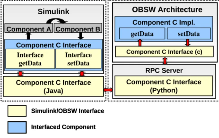
Finally, the global interface mechanism architecture is the following: Simulink Simulink Component C Interface Interface getData Interface setData Component C Interface (Java) RPC Server Component C Interface (Python) Component C Impl. Component C Interface (c) getData setData OBSW Architecture OBSW Architecture Component A Component B Simulink/OBSW Interface Interfaced Component Simulink Simulink Component C Interface Interface getData Interface setData Component C Interface (Java) RPC Server Component C Interface (Python) Component C Impl. Component C Interface (c) getData setData OBSW Architecture OBSW Architecture Component A Component B Simulink/OBSW Interface Interfaced Component
Figure 5: Overview of the interface mechanism 3.2 Simulink/OBSW Synchronization
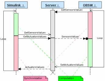
The interface mechanism shall assure that the signal frequencies are preserved during the simulation. The software components send get and set requests to the XML-RPC server according to their own base frequency and possibly to some sub-frequencies. For each software component, both the input and output data are gathered by frequency. Simulink interface blocks are configured to have the same relative frequencies for each set of signals. As a consequence, each time a value is computed by Simulink it shall be consumed by the OBSW and conversely. For that a synchronization mechanism is implemented in the python component class added to the XML-RPC. This mechanism causes the RPC calls to be blocking if the data has not been refreshed since the last call. To clarify the explanation, lets suppose that only one component is implemented in software. For each set of signals, the OBSW component tries to get its input data from Simulink. If the data are not available it is blocked. When Simulink set the corresponding data, the OBSW is awoken, get the data and begin to compute its outputs. In the mean time Simulink tries to get the outputs of the component and is blocked because they are not yet available. Finally the OBSW component set its output data, and Simulink can resume its execution and compute the rest of
the model. The sequence diagram figure 6 illustrates this mechanism.
Once in Simulink the data can obviously be over-sampled (by using a transition rate block).
Figure 6: OBSW/Simulink synchronization 3.3 Real-time representativeness
To preserve the real-time representativeness of the simulation the whole OBSW is frozen when a call to a getValues is blocked. As a consequence the task scheduling and the relative task execution time are preserved but all the data acquisitions take no time from the OBSW point of view. Simulink/OBSW interface mechanism provides a good temporal representation for systems, which use a data acquisition server running in a dedicated task. The interface mechanism creates also a big overhead mainly due to network latencies and Simulink computation time. On representative example our simulation is three times slower than the real time. 3.4 Automatic generation of the Simulink/OBSW Interface
The Simulink/OBSW interface mechanism (Simulink blocks, the Java and Python classes and the OBSW part) is only dependant of the types, the names, and the frequencies of the data exchanged between Simulink and the OBSW. As a consequence it can be automatically generated to speed-up and simplify the interfacing process.
A dedicated IDL compiler has been developed and integrated in the already existing set of IDL compilers. For each component, this tool generate four files:
• A Simulink model for the incoming signals (.mdl) • A Simulink model for the outgoing signals (.mdl)
• A Java Class which received the signals from Simulink and transferred them to the Python server (.java)
• A Python class which enables the XML-RPC server to handle the component communication (*.py)
• A C file which implements the functions to get and set signals values from the OBSW (*.c) 3.5 Automatic generation of the component code The Simulink/OBSW interface mechanism can be associated an automatic code generator (ACG) to produce a fully automatic implementation process. The code of the component models are generated with the ACG and integrated into the modular software architecture with the code generated by the IDL compiler. This process is a mean of quickly prototyping a component on a representative hardware environment. If the automatic code generator used authorizes to define the prototype of the functions used to get and set the input and output signals, no extra manual code is needed to interface the generated OBSW code with the interface mechanism.
The global process is the following:
• Generation of the component skeleton (from IDL)
• Generation of the component code (from Simulink model)
• Integration of the component code in the generated skeleton
• Generation of the interface mechanism
• Exchange of the Simulink block by the interface blocks generated
• Dispatch of the interface code (Java class in Matlab path, add of the Python class in the XML-RPC server and add of OBSW interface code in the project compilation file)
• Compilation of the binary
This process is mainly automatic. It does not require a lot of manual intervention and as a consequence is very fast.
3.6 Software distribution
The global architecture can be distributed on three machines:
• A Matlab station where the model part of the architecture runs
• A host machine where the ground/board server runs. This machine is linked with the real hardware target where the generic avionic and the software components run.
• A Ground Station where an HMI displays the measures (TM) received from the board and also enables the user to send commands (TC) The various machines are connected through a classical network link.
Figure 7: Software distribution
4. Assessment and Results
4.1 Utilization Example
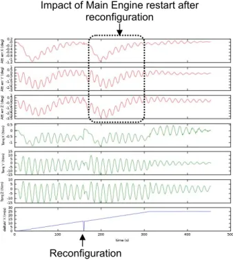
The ESA ExoMars mission aims at sending a rover on mars. The process described in this paper has been used in the preliminary studies of this project. In case of a crash of the nominal processor module during the boost phase of the ExoMars orbit insertion, the Main Engine (ME) shall be stopped at most 10 seconds. Once the ME is operational, the satellite attitude must converge again.
The processor module warm redundancy concept has been developed to guarantee at any conditions a quick restart of the OBSW on the redundant processor module, to be able to resume the attitude control and the boost.
Simulink/OBSW interface has been used to set-up a Fail-Op demonstration with the following goals: • Refining and verifying the warm redundancy
concept specifications, in both HW and SW fields.
• Demonstration that the timing constraints are met (boost resumed before 10 seconds).
• Demonstration of the potential re-use of the AOCS source code in the frame of the ExoMars development
The architecture presented in the previous chapters has been tailored for the purpose of this demonstration:
• Use of two LEON processor boards.
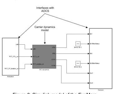
• Modelling of the carrier dynamics in Simulink (figure 8)
• Reuse of the AOCS component of another project
Interfaces with AOCS
Carrier dynamics model
Figure 8: Simulink model of the ExoMars demonstration
The crash of the Nominal processor module during ME firing has been achieved in the demonstration by disconnecting the board power.
After the failure, the redundant processor module shall be woken up and restore the previously saved context to resume the ME firing as soon as possible. When the nominal processor module is switched off, Simulink model is blocked because there are no available actuators data. When the redundant makes the first sensor acquisition, the nominal processor module is put in stand-by mode and some forced AOCS cycles are executed to compute the dynamics of the carrier during the crash.
The demonstration has provided the expected results:
• The second processor module was reconfigured and it had taken back the control of actuators in less than 5000 ms.
• The mission was not lost even if one of ΔV (targeted or accumulated) data was corrupted. • Additional measures were provided (Maximum
attitude error, time to stabilize the carrier attitude)
Figure 9 shown an example of result provided by the demonstration:
Figure 9: Simulation Results 4.2 Improvement of the design process
The principle presented improve the development process on the following points:
• Incremental transformation:
The possibility to incrementally implement the component in software makes it possible to parallelize the component development. A software component can be developed and tested alone without breaking this architecture.
• Early and representative tests:
Simulink/OBSW interface mechanism enables the developers to perform closed-loop simulation during all the development steps. As a consequence the components implemented in software can be tested and validated earlier on the target and with representative input values. It is not necessary to wait the development of complex hardware test bench to begin to test the component implementation.
• Early validation of the component architecture: The overall component architecture can be validated on the real target. Performance and metric measures
can be obtained earlier in the software development cycle.
• Proof of reusability: Impact of Main Engine restart after
reconfiguration The Simulink/OBSW interface is a mean of proving
the reusability of a component already implemented in software. This component can be quickly integrated in the architecture of the new project and it is possible to prove that the component fits in the architecture and meets the new requirements.
5. Conclusion
As shown by the description of the ExoMars use case, Simulink/OBSW interface can really improve the development process of component-based architecture. By enabling parallelization of the component development, fast-prototyping of the architecture and earlier and more representative tests it simplifies the software development planning. It is also a good way to quickly prove the reusability of existing component implementation.
Reconfiguration Even if the mechanism described here use an
intermediary server, it is possible to directly connect Simulink to the target board if this one provides an UDP or TCP link. So, the mechanism is not dependent of a particular kind of operating system or API and can be used on most of the embedded target.
Although with positive impact, this process does not enable to simulate every phenomenon due to its poor real-time representativeness. For that, the future work will try to increase the real-time representativeness by lowering the network communication latency.
6. Acknowledgement
I would like to acknowledge J. Villa (TAS-F) for its cooperation on the ExoMars demonstration development.
7. References
[1] C. Moreno and G. Garcia: "Plug & Play architecture
for on-board software components", proceedings of
DASIA, 2003.
[2] Interface Description Language, www.omg.org
[3] XML-RPC, Simple cross-platform distributed
computing, based on the standards of the Internet, www.xmlrpc.com.
8. Glossary AOCS: Attitude and Orbit Control System ESA: European Space Agency
HMI: Human Machine Interface IDL: Interface Description Language OBSW: On-Board Software
ME: Main Engine PM: Processor Module RPC: Remote Procedure Call SW: Software
TAS: Thales Alenia Space TC: Telecommand TM: Telemeasure