Development of a Low-Cost Underwater Manipulator
byLauren Alise Cooney
SUBMITTED TO THE DEPARTMENT OF MECHANICAL ENGINEERING IN PARTIAL FULFILLMENT OF THE REQUIREMENTS FOR THE DEGREE OF
BACHELOR OF SCIENCE AT THE
MASSACHUSETTS INSTITUTE OF TECHNOLOGY June 2006
© 2006 Lauren Alise Cooney. All rights reserved
The author hereby grants to MIT permission to reproduce and to distribute publicly paper and electronic copies of this thesis document in whole or in part in any medium now
known or hereaftr created.
Signature
of
Author. .
....
_...
.E
partment of Mechanical EngineeringMay 18, 2006
Certified by ...
-- .
...-
....
/'~ ~
John Leonard
,,ssociate Professor of Mechanical Engineering Thesis Supervisor
,C
Accepted by ...
- ... .. ..,...
...
John H. Lienhard VProfessor of Mechanical Engineering Chairman, Undergraduate Thesis Committee
MASSACHUSETTS INSTITUTE
OF TECHNOLOGY
AUG 0 2 2006
Development of a Low-Cost Underwater Manipulator
byLauren Alise Cooney
Submitted to the Department of Mechanical Engineering on May 18, 2006 in Partial Fulfillment of the Requirements for the degree of Bachelor of Science in
Mechanical and Ocean Engineering
ABSTRACT
This thesis describes the design, modeling, manufacture, and testing of a low cost, multiple degree-of-freedom underwater manipulator. Current underwater robotic arm technologies are often expensive or limited in functionality. The goal of this research is to produce a multiple degree-of-freedom manipulator utilizing relatively inexpensive, commercial off-the-shelf servo motors. This project is designed for low-payload (< 0.5 kg) and shallow depth operation on a small remotely operated vehicle.
A completed underwater manipulator has been built using the new servo housing design. Static and dynamic waterproofing techniques have proven satisfactory, offering a solid design for waterproofing of servo motors. Preliminary tests of the integrated servo arm
system indicate that the arm will operate successfully in the underwater environment. This design is anticipated to be used on an underwater vehicle in June 2006, as well as in
future undergraduate ocean engineering design subjects.
Thesis Supervisor: John Leonard
Acknowledgements
I would like to express my sincere appreciation to the following people that made this project possible:
· My advisor, Professor John Leonard.
* The MIT ROV Team, in particular, Daniel Walker, Thaddeus Stefanov-Wagner, and Kurt Stiehl. As well, thank you to the ROV Team's donors, who provided the financial support for this project.
* Mark Belanger and the Edgerton Student Machine Shop. * The MIT Towing Tank.
* The Ocean Engineering Teaching Laboratory. * Zachary Gazak.
Table of Contents
ABSTRACT 3 Acknowledgements 5List of Figures
8
List of Tables
9
Chapter 1 Introduction 111.1 Review of the State of the Art of Underwater Manipulators
11
1.2 Design Goals 13
1.3 Outline 15
Chapter 2 Mechanical Design
17
2.1 Motor Selection 17
2.2 Motor Housings 19
2.3 Linkages 20
2.4 Cost
22
2.5 Manipulator Arm Photographs
22
Chapter 3 System Modeling 25
3.1 Rigid Body Kinematics
25
3.2 Rigid Body Dynamics
26
3.3 Fluid Effects 28
3.3.1 Hydrostatics 28
3.3.2 Hydrodynamics 28
3.3.3 Previous Research on Hydrodynamic Modeling of
Underwater Manipulators
29
Chapter 4 Performance Assessment
31
4.1 Control Architecture 31 4.2 Servo Characterization 32 4.3 Arm Characterization 32 Chapter 5 Conclusions 33
5.1 Summary of Contributions
33
5.2 Future Research 33Appendix A:: Mechanical Drawings 35
List of Figures
Figure 1.1: Schilling Robotics TITAN 4 [1] 12
Figure 1.2: SeaBotix TJG300 Three Jaw Grabber [2 12
Figure 1.3: MIT ROV Team 2004 Vehicle
14
Figure 1.4: Gripper Assembly and Gearing [5] 15
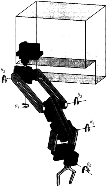
Figure 2.1: Arm with End-Effecter Defining Degrees-Of-Freedom
18
Figure 2.2: Spring-Loaded PTFE Seal [6] 20
Figure 2.3: Section View of Motor Housing
21
Figure 2.4: Photograph of Inside of Motor Housing
22
Figure 2.5: Photograph of Arm Assembly
23
Figure 2.6: Photograph of Arm in Extended Position
24
Figure 2.7: Photograph of Arm in Stowed Position
24
Figure 3.1: Reference Frames
25
List of Tables
Table 1.1: State of the Art of Underwater Manipulator Technology
13
Table 2.1: Motor Torque Requirements
17
Table 2.2: Manufacturer's Motor Characteristics
[5]19
Table 3.1: Denavit-Hartenberg Parameters [8] 26
Chapter 1 Introduction
The ability to operate in the subsea environment presents many opportunities and benefits in research, commercial, and military endeavors. However, the added challenge of working underwater often results in technologies that are either very expensive or have limited functionality, a trend largely reflected in underwater robotic arm technologies. The goal of this research is to develop a working five degree-of-freedom (DOF) underwater manipulator created from low cost, off-the-shelf parts.
1.1 Review of the State of the Art of Underwater Manipulators
Current underwater manipulator technologies largely fall into two categories: high functionality at high cost, or limited functionality at low cost. Robotic arms with multiple degrees of freedom are typically designed for medium- to large-scale remotely operated vehicles (ROV's). These manipulators are often expensive, heavy, and large. For example, the Schilling Robotics TITAN 4, shown in Figure 1.1, is a popular deep sea manipulator employed on large ROV's working in the offshore industry. This arm is made primarily out of titanium and is powered by hydraulics. Although the TITAN's seven degrees-of-freedom are an attractive feature, due to its large weight and expense (76 kg in seawater, >$150,000), this class of manipulator is not feasible for smaller low-cost vehicles.
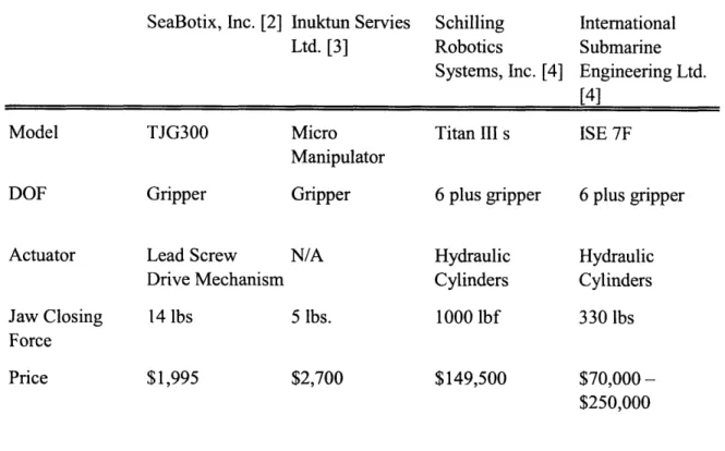
At the other end of the spectrum, lower cost manipulators commonly have much less functionality. The SeabotixTJG300 Three Jaw Grabber, as shown in Figure 1.2 and as described in Table 1.1, has only a gripping mechanism. Because of this limited performance, a greater dependence is placed on vehicle maneuverability in order to achieve complex manipulator tasks.
Figure 1.1: Schilling Robotics TITAN 4 []
Table 1.1: State of the Art of Underwater Manipulator Technology
SeaBotix, Inc. [2] Inuktun Servies Schilling International Ltd. [3] Robotics Submarine
Systems, Inc. [4] Engineering Ltd. [4]
Model TJG300 Micro Titan III s ISE 7F
Manipulator
DOF Gripper Gripper 6 plus gripper 6 plus gripper
Actuator Lead Screw N/A Hydraulic Hydraulic
Drive Mechanism Cylinders Cylinders
Jaw Closing 14 lbs 5 lbs. 1000 lbf 330 lbs
Force
Price $1,995 $2,700 $149,500
$70,000-$250,000
1.2 Design Goals
The design of an underwater manipulator encounters challenges from the combined complexities of subsea operations and robotic arm design, which are further intensified when trying to do so in a cost-efficient manner. The waterproofing of electronics and other sensitive elements is critical to a working system. System design is driven by desired payload capacity and end-effecter positioning and speed, as well as additional forces from static and dynamic fluid effects.
Design considerations for this arm are made with the anticipation of functioning on a small remotely operated vehicle (12 x 12 x 12in) built by the MIT ROV Team to compete in the national ROV competition organized by the Marine Advanced Technology Education Center (MATE) and the Marine Technology Society (MTS) ROV Committee. The 2006 MATE ROV Competition is to be held at the Neutral Buoyancy Laboratory at the NASA Johnson Space Center in Houston, Texas. The competition takes place in a fresh water pool, where the maximum operating depth is 40 feet. There are several tasks that the ROV must complete within the 30 minute competition time limit. The ROV must transport an electronics module weighing 1.5 kg underwater to the pool bottom, and secure this module into a frame. The module door needs to be opened-requiring 1 N of force-so that a 1" PVC probe weighing 0.3 kg underwater may be inserted into the port on the module.
In addition, there are design requirements created by the ROV itself. Low weight and small size of the stowed arm are essential in minimizing manipulator effects on vehicle operations. The arm should also be capable of operating off of a bottomside power supply rated at a nominal 12 V and 20 Ah. Topside communication with the arm will be through a fiber-optic tether. Of overarching concern for the arm is budget. The ROV Team operates off of donations from both industry and academia. Keeping the arm cost-effective (<$500) would make it a feasible enterprise, as well as increase the viability of reproduction.
Figure 1.3 shows the ROV Team's vehicle for the 2004 competition. The gripper assembly in Figure 1.4 was used on this vehicle to retrieve a weighted 2" PVC pipe off of the bottom of a swimming pool and to bring it up to the surface. Although this gripper does not have much in the range of maneuverability, it was acceptable for this mission, as the only functional requirements were the ability of the ROV to land within grasping range, and that the gripper could maintain a tight hold on the object.
Figure 1.4: Gripper Assembly and Gearing [5]
For this year's competition, however, relying on the ROV's propulsion/control system to perform tasks such as plug the instrumentation probe into the module port could be time inefficient and difficult. An underwater manipulator with high functionality would provide several advantages for the ROV competition, and to underwater operations in general. A multiple degree-of-freedom robotic arm would allow for more precise control in manipulation tasks, as opposed to a vehicle with a single gripper which would require high levels of hovering control.
1.3 Outline
This thesis documents the development of a low-cost underwater manipulator. The mechanical design process is described, including motor selection, housing design, manufacturing, and cost. Modeling of the system is then performed, for rigid body kinematics and dynamics, and an evaluation of fluid effects. Preliminary performance assessment, conclusions and suggestions for future research are discussed.
Chapter 2 Mechanical Design
This chapter describes the mechanical design and manufacturing of the manipulator. Component selection, development, and integration are discussed. Photographs of parts and the assembled arm are shown in Figures 2.4 through 2.7. A bill of materials is listed to illustrate the low-cost aspect of the design. Mechanical drawings for components can be found in Appendix A.
The manipulator is made up of five direct serial drive revolute joints. The end-effecter was not developed for the purposes of this thesis. The configuration of the manipulator is similar to that of a human arm, with a two degree-of-freedom shoulder connected to the base (01 and 0 ), a one degree-of-freedom elbow (03), and a two degree-of-freedom wrist
(04 and 05) (Figure 2.1).
2.1 Motor Selection
Hobby servos are an appealing technology, as they are readily available with gear trains and feedback positioning electronics at a relatively low cost. A new breed of robotic servos marks a departure from standard model airplane servos, as they boast high torque and over 180 degrees of rotation.
Torque requirements for each motor are determined using a static moment balance, where buoyancy effects are considered and hydrodynamic effects are small at very low speeds. These calculations include the weight of an end-effecter and a 1 N weight. Table 2.1 presents the torque requirements for the case of hydrostatically optimized motor housings that achieve neutral buoyancy.
Table 2.1: Motor Torque Requirements Torque Requirement In Air In Water Motor 2 4.53 N-m 1.309 N-m Motor 3 1.856 N-m 0.562 N-m Motor 4 0.473 N-m 0.158 N-m
03 0f1 0
f Z6
04,L.
-1H
Figure 2.1: Arm with End-Effecter Defining Degrees-Of-Freedom
!, ___
' ' :·· r: .... .. .. .~
~ ~ ~ ~ ~ ~~··
, " ,
t;
Two servo motors produced by Hitec, Inc, make up the drive framework for the manipulator: the HS-805BB and the HS-755HB. The HS-805BB is used to drive the arm's shoulder and elbow joints, as these joints require more torque, but can also handle a larger size motor as the moment arm created about the base motor is minimal. The HS-755HB motor drives the two wrist joints as they do not require as much load carrying capacity.
Table 2.2: Manufacturer's Motor Characteristics [6]
HS-755HB HS-805BB
Stall Torque 13.2 kg*cm 19.8 kg*cm Speed (no load) 0.23 sec/60 deg 0.14 sec/60 deg Operating Angle ±90 deg ±90 deg Operating Voltage 4.8 - 6.0 V 4.8 - 6.0 V Current Drain (no 285 mA 830 mA
Dimensions
59 x 29 x 50 mm
66 x 30 x 58 mm
Weight 110g 152 g
Price 27.99 USD 39.99 USD
2.2 Motor Housings
The motor housings are constructed out of black nylon 6/6, chosen for its good tensile strength, dimensional stability, machinability and relatively low cost compared to plastics of similar performance level. Large pieces of stock, however, were more expensive than several smaller pieces of stock with the same cumulative volume. Therefore, the housing is made up of two smaller equal sized blocks. A standard face seal O-ring groove creates the static seal between the two housing components and the outside environment.
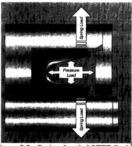
The dynamic seal for the motor shaft is provided by a spring-loaded PTFE seal (Fig 2.2). These seals employ U-Cup lip seal geometry using a canted coil spring that creates a sealing force that is also energized under dynamic conditions. The ratings for these seals are well within the operational limits for this project (pressure x velocity limit of 75,000 psi-fpm). For deeper applications, an alternative dynamic seal would need to be applied.
71
Figure 2.2: Spring-Loaded PI1E Seal L'J
Shaft seals prove difficult for hobby servos as a servo horn is directly connected to the final gear stage, leaving no shaft exposed to create a seal around. The final design consists of a commercially available inline shaft adaptor connected to the servo horn, around which the shaft seal is created.
Plastic flanged sleeve bearings are utilized at both the output shaft and linkage pivots. The bearings chosen are of material Rulon LR, preferred for its low friction and because it does not absorb water. These bearings act as constraints in the radial direction and also handle radial and thrust loads. The bearings used at the linkage pivots also serve as a low friction pivot point.
2.3 Linkages
Linkages are constructed out of 3/8" clear polycarbonate, a material that exhibits good strength and relative ease of machining, yet low weight as compared to metals such as aluminum. Each motor driven linkage operates in parallel with a load-sharing linkage connected to the motor housing via a freely rotating pivot. Linkages are secured to shafts using a dowel pin.
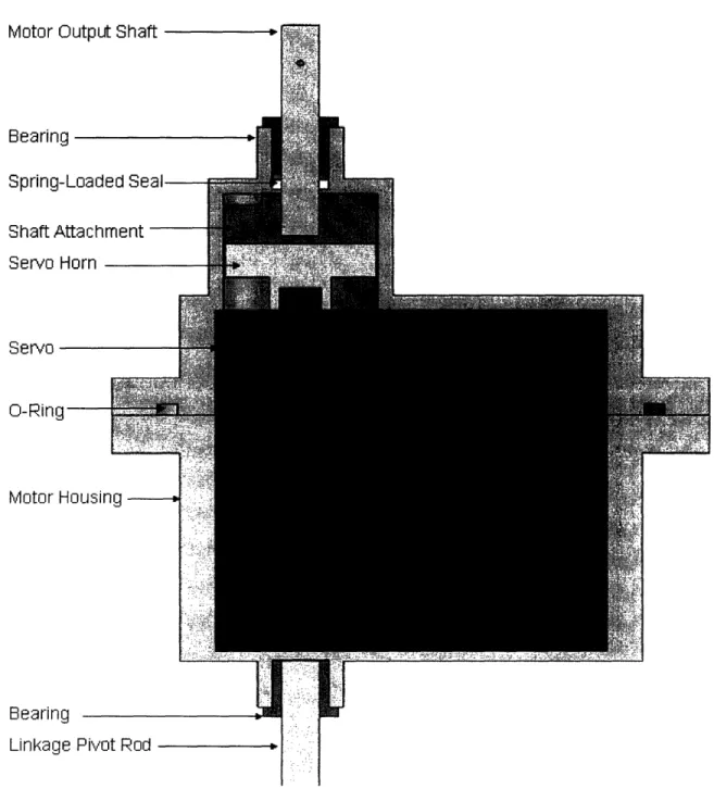
Motor Outpu Spring-Load Spring-Load Shaft Attach Servo Horn
servo
O-Ring Motor Housii BearingLinkage Pivot Rod
Figure 2.3: Section View of Motor Housing
~~~~~~~~~
I~~~~~~~llr
Ro~rirnI I ~ " I I
I
2.4 Cost
Table 2.3 presents the cost of materials used in the final manipulator design, not
including the cost of an end-effecter or PIC microcontroller for control. As can be seen,
the total cost is significantly less as compared to even the single degree-of-freedom
grippers listed in Table 1.1.
Table 2.3: Bill of Materials
Unit Price Quantity Total Price IMotors IHitec HS-755HB 1/4 Scale Karbonite Gear Servo U | $27.99 | 21 $55.98
Hitec HS-805BB Mega 1/4 Scale 2BB Servo U $39.99 3 $119.97
MaterialsBlack Nylon 6/6 $114.80 $114.80
Clear Polycarbonate Sheet $23.79 1 $23.79
Other Aluminum Shaft Attachment $9.95 5 $49.75
Sleeve Bearing $1.88 10 $18.80
Spring-Loaded PTFE Seal PTFE, 1/16" Width, 1/4" Shaft Dia, 3/8" Seal Od $8.00 5 $40.00
Unshielded 22AWG UL2464 3 COND, 100" $31.75 1 $31.75
Grand Total: $454.84
2.5 Manipulator Arm Photographs
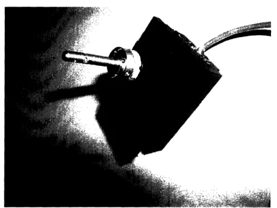
Figure 2.4: Photograph of Inside of Motor Housing
. . : '. . j, - T.... , i z .. i' , , S , , 4 M.
-11-4 10
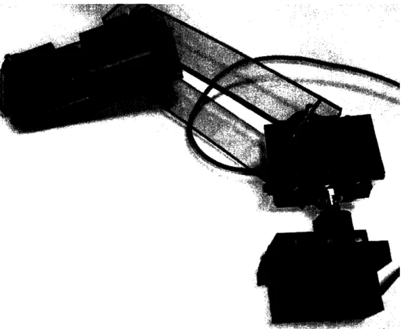
MOIX10- AftFigure 2.5: Photograph of Arm Assembly
: I I-:17 .1.111 1.11111%
Figure 2.6: Photograph ot Arm in
Extendaea
osition
Chapter 3 System Modeling
This chapter presents the kinematic and dynamic analysis of the manipulator. In addition, fluid effects are defined and discussed.
3.1 Rigid Body Kinematics
The system in consideration can be idealized as 5 revolute joints, each rotated at an angle 0i with respect to the orientation of its connecting serial linkage of length fi (Fig 3.1). The Forward Kinematic Equations are used to describe the location and orientation of the end-effecter in the fixed vehicle reference frame 0- x0yoz0. For the purposes of this
project, the vehicle is considered to be stationary within the fixed earth reference frame. The position of the end-effecter is described by the three coordinates [Xe, ye, Ze].
I
r; -1103 04 05
t2 t3 t4
Figure 3.1: Reference Frames
Forward Kinematic Equations:
Xe = {2 cos82 + e3 cos(02 + 3)+ f4 cos(0 2 +3 + 04) + (w4 + 5 )sin(02 +03 + 4)}cos01 'e = { 2 cos 0 3 cos(2 + 03)+ e4 cos( 2 +03 + 04) + (w4 + 5)sin(02 + 03 +
0
4)}sin01Table 3.1: Denavit-Hartenberg Parameters 8] i ai ai d i i 1 O -90 ° e' a0
2
E2 0 0 02 3 t3 0 0 034
W4 -90° '4 04 5 i5 0 0 05 where:a
i Link length, distance from Z i to Zi+ along Xi;ai Link twist, angle from Zi to Zi+, about Xi,
d Link offset, distance from Xi_, to Xi along Zi, and
0 i Joint angle, angle between Xi-, to Xi along Zi.
Homogeneous transformation Ai:
Soi Ca
iSo
iia
ai
co
iSoi
CO
iC
a i-Ci S
a iaisO
io
S ai Cai0 0 0 1
3.2 Rigid Body Dynamics
Characterizing the motion of the arm within the fixed vehicle reference frame is critical to understanding arm dynamics. These equations can become quite complicated. For the purposes of this research, primary interest is with regard to large motions of the arm. Therefore, in the analysis in this section, rotations in 01, 02 and 03 only will be considered, and the joints at 04 and 05 will be rigid.
The Jacobian matrix J describes the relationship between joint angular velocity ,iand the velocity of the end-effecter in the reference frame:
K' 8t)s Zm I I tQ ~C'I ( 0 ( 0 ( 8Q Q (Z-Q c c( cOt CZ --' I ( ( ( 0 0 ( I -I ( CO cO
IIcC;
~ ~OI
rg
I I r CI o Cc + ) 0+C + + CD C D L. :, + ) + +O " +' o o 0L ICD + ~ 2 C+'D + + + + + C (_ .Co r CN -I- + C' +> + + + C4 0 , Co - +_o
CD CO
'
*q r (C r +0a C o + +0
@4
C)
o CO C @, c) C") Co CO 0 I I a' @ a'- ' o C) C@(NJ C'D I I --. I ('14 'O50
r + o + r 0 + C-+-N 4D a',1 + + C +I
C-- C-04 04 + (CNr, Co + + + (f) o 0 .C C'q <-("
e1 I II I I C)3.3 Fluid Effects
Underwater operation adds both static and dynamic complexity. The hydrodynamic modeling of underwater manipulators is quite complex, therefore, discussion in this
section is aimed more at an overview of the hydrodynamic effects and their possible impact on performance, rather than computation of exact values.
3.3.1 Hydrostatics
In static analysis of underwater bodies, both the gravitational force acting on the body mass and buoyancy force must be considered. Archimedes's principle states that the buoyant force is equal to the weight of the fluid displaced. Therefore,
Fbuoyancy = Pwater submerged g Fgravity = mbodyg
FtotaI = Fbuoyancy -Fgravity
3.3.2 Hydrodynamics
Added mass is the effect of fluid inertia in the environment on a moving body. This is not a phenomena that extends to above water operations, however, the effect is vastly more significant subsea as the density of water is much more comparable to the density of the body of interest. The added mass coefficient is dependent on body geometry and motion.
Fluid viscosity also creates drag and lift forces on a body. Drag acts in parallel with the flow velocity on the body:
Fdrag =
pU
2A Cd
(Re)
where p is the fluid density, U is the flow speed, A is the projection of the body in the direction of flow, and Cd is the drag coefficient which is dependent on Reynold's number:
Re = plUID
'U
where gt is the dynamic viscosity of the fluid. The lift force acts normal to flow velocity:
Flif
1= pU2ACI (Re,a)
For a cylinder in non-uniform flow, the total added mass and drag forces can be found using Morison's equation, which relates the inertial and drag forces:
dF =-C, * pA
Udl
-C * pWIUIUdl
3.3.3 Previous Research on Hydrodynamic Modeling of Underwater Manipulators
The complexity of hydrodynamic modeling of underwater manipulators is largely due to a lack of understanding of the 3-dimensional hydrodynamic effects of manipulator systems. To be considered are flow effects around rotating joints and linkages in close proximity, and their dependency on rapid movement and unsteady motions.
It has been determined through experimental research that using constant added mass and drag coefficients for a manipulator body are not sufficient for complete analysis [9]
Leabourne and Rock [10] expanded on this research, and found the drag and added mass coefficients to be dependent on elbow angle in their two degree-of-freedom arm model. In these tests, the maximum value of the drag coefficient for the manipulator model was
Chapter 4 Performance Assessment
This chapter describes the performance of the arm design presented in previous chapters. The overall arm control architecture is discussed, and preliminary testing of motors and the arm are assessed.
4.1 Control Architecture
Hobby servos are controlled using pulse width modulation (PWM). The servo angle is regulated by varying the signal pulse width, where 1.0, 1.5, and 2.0 msec prescribe motor rotation angles of -90 deg, 0 deg, and +90 deg respectively.
Signal
50 Hz Period 1 .0 -2.0 msec Pulse Width
*
-Tine
Figure 4.1: Pulse Width Modulation
The control system and user interface for the manipulator were developed by members of the ROV Team. The arm is operated using a master-slave system. The master is topside, and is of identical kinematic design to the actual manipulator. Each joint of the master has a position potentiometer that measures the motion of the operator as the master is moved to simulate the position of the actual arm. The desired position is chosen in parallel with real-time video feed of the manipulator's location.
The control system employs two PIC microcontrollers operating in closed loop, one-way communications control. The topside PIC reads in the potentiometers in the joints of the master arm, converts the values into motor angles and sends the info down a fiber optic tether. The PIC on the bottom side receives the data, converts the motor angle and sends the signal to the motors.
4.2 Servo Characterization
An HS-805 servo was tested using a PIC outputting PWM. The motor was enclosed in its waterproof housing for both air and water tests. Maximum slew rate was determined by measuring the time for the motor shaft to rotate clockwise, and averaging this rate over 10 trials. Power consumption without load was measured as the current draw observed under no load, with a voltage limited power supply at 6.0 V. Maximum power consumption with load was the largest current draw observed over the testing period, under voltage limited power supply of 6.0 V. These characteristics are shown below in Table 4.1. As can be seen, the max slew rate and power consumption without load are fairly close to those expected by the manufacturer's specifications. The higher measured values are expected, as the motor shaft, even under no load, is experiencing additional torque due to the spring-seal. These discrepancies are not large enough to be cause for concern with regards to housing and shaft seal effects on motor performance.
Table 4.1: HS-805 Servo Characteristics
Manufacturer's
Specifications Motor in Air Motor in Water
Max Slew Rate 180 Deg / 0.42 Sec 180 Deg / 0.54 Sec 180 Deg / 0.57 Sec Power Consumption
w/o Load 4.98 Watts 5.64 Watts 5.88 Watts
Max Power Consumption w/
Load N/A 11.22 Watts 12.66 Watts
4.3 Arm Characterization
The tests performed with the assembled arm consisted of controlling only the first and second motors, one at a time. The arm was assembled using the first four motor housings and the two linkage pairs as seen in Figure 2.5. The motor that was being tested was given a PWM signal to control the position of the motor shaft. Due to time constraints and technical difficulties, the abilities of these motors to provide sufficient torque was only observed qualitatively. Both motors were able to drive their successive linkages and attached motors without stalling. The slew rate did not appear to vary significantly from tests with no load.
Chapter 5 Conclusions
This chapter concludes the thesis by summarizing the contributions of this research and making recommendations for future work.
5.1 Summary of Contributions
This thesis presents the foundation for a low-cost, several degree-of-freedom underwater manipulator for a small ROV. The primary achievement is the design of a waterproof servo motor housing consisting of static and dynamic seals. Several of these housings were manufactured and proven to be watertight, and to have minimal effect on motor performance. Kinematic and dynamic analysis was performed, as well as the discussion of fluid effects for the manipulator. In addition, a preliminary manipulator arm was assembled, which required the design and manufacturing of motor shafts, linkages, and supports. Preliminary underwater tests of the motor housings and of the assembled manipulator were successful, and encourage the continued development of the arm.
5.2 Future Research
In order to make this arm ready for field operation, the motor housings should be tested to maximum designed depth. If more extreme operating depths are desired, a new pressure compensation system must be developed, such as the oil regulating bladder system described by Di Pietro for the ROV JASON manipulator [11]. An end-effecter is currently being developed for the arm. Continued arm characterization needs to be performed using the end-effecter with various payloads.
The primary drawbacks to the current motor housing design are cost of material and manufacturing time. A large portion of the nylon stock used to create the housing is hollowed out and discarded during manufacturing, which is an inefficient use of time and money. Using a readily available, inexpensive, waterproof housing would be a significant improvement on manufacturing and cost. Another interesting avenue would employ inexpensive DC motors with positioning electronics. DC motors would reduce complexity in the shaft seal and possibly result in more compact motor housings.
Appendix A
0.400 3.080 I- -- -Link tco c) 0.400 2.818 ,q COI ',0~ t:Od
++ [H -Q A J Kt 7.548 A----/er Link ;~9.500
9.500 -- -1 7-I Is . ._ .- _ _ !1 .-A,---- I.-II I ++-J_ l 4. J_-C co I I If I Cbsa)
0
Eo an2)
o
o
1)IX
('O O
+ -c ooI-
D
607'0 gL'L L OOL0'O 9L0'0I'
---1
S . I--A-1
..II
L
I0a ._ c"
0
0-CO -cog'o
---
1
---I
---U
cO cO0f
ol
, + '0o
0 co o L176'(_X_!
,,--.. --\ & - | --- jl .~1 2C9, 1 Jii --I _I ---t 'I-, X - .,11-a.
0
a,)
O
o
C
= D
08'L---
1---
11 --- - ---l
--,J-t79t7'L 060'L - 1
F--H
I · tL_ I I LI I I= .- l Lil I Ot77n 099'L ---I I-:p t--F l i-I -I--L 39E
n
0
-o
m
L-C
O
--CT) C
I
D
-. E3-7YVV 2 ---H_ i I I r-_ =---
3
.
_BS I E_~
IBibliography
[1] "Manipulator Comparison." Product Literature. Schilling Sub-Atlantic. 15Apr. 2006 <http://suab4599.demonweb.co.uk/manipulators.html>.
[2] "LBV Grabber." Product Literature. SeaBotix, Inc. 15Apr. 2006
<http://www.seabotix.com/products/pdf_files/LBV_GrabberA4.pdf>.
[3] "ISL MicroManip." Product Literature. RoboProbeTecnologies. Inc. 15Apr. 2006 <http://www.roboprobe.com/DOWNLOADS/D 13_IK_MICROMANIP.PDF>. [4] Yuh, J, and M West. "Underwater Robotics." Advanced Robotics 15 (2001):
609-639.
<http://www.ingentaconnect.com/search/article?title=underwater+robotics&titlet
ype=tka&year_from= 1998&yearto=2005&database= 1 &pageSize=20&index=5> [5] Stanway, M. et al. "ROV Castor: Design of a Multi-Mission Remotely Operated
Vehicle." 2004.
[6] "Giant Scale Servos." Product Literature. Hitec RCD USA Inc. 03 Feb. 2006 <http://www.hitecrcd.com/homepage/product_fs.htm>.
[7] "FlexiSealTM." Product Literature. Parker Seals. 10 Mar. 2006 <http://www.parker.com/packing/cat/english/5315_FlexiSeal.pdf.
[8] Craig, John J. Introduction to Robotics. 2nd ed. Reading: Addison-Wesley Company, Inc, 1989.
[9] McLain, T., Rock, S., and Lee, M. "Experiments in the Coordinated Control of an Underwater Arm/Vehicle System." Journal of Autonomous Robots 3 (1996): 213-232.
<http://www.ingentaconnect.com/content/klu/auro/1996/00000003/00000002/001 16327>
[10] Loeabourne, K., and Rock, S. "Model Development Of An Underwater Manipulator For Coordinated Arm-Vehicle Control." (1996). 15 Apr. 2006 <http://sun-valley.stanford.edu/papers/LeaboumeR: 98.pdf>.
[11] Di Pietro, David. Development of an Actively Compliant Underwater
Manipulator. Diss. Massachusetts Institute of Technology, 1988. 20 Jan. 2006 <http://dspace.mit.edu/handle/1721.1/14582>.
MITLibraries
Document Services
Room 14-0551 77 Massachusetts Avenue Cambridge, MA 02139 Ph: 617.253.5668 Fax: 617.253.1690 Email: docs@mit.eduhttp: //libraries. mit. edu/docs
![Figure 1.1: Schilling Robotics TITAN 4 []](https://thumb-eu.123doks.com/thumbv2/123doknet/14732533.573346/12.918.272.653.165.460/figure-schilling-robotics-titan.webp)
![Figure 1.4: Gripper Assembly and Gearing [5]](https://thumb-eu.123doks.com/thumbv2/123doknet/14732533.573346/15.918.195.753.190.386/figure-gripper-assembly-gearing.webp)
![Table 2.2: Manufacturer's Motor Characteristics [6]](https://thumb-eu.123doks.com/thumbv2/123doknet/14732533.573346/19.918.148.652.270.522/table-manufacturer-s-motor-characteristics.webp)