HAL Id: hal-00903634
https://hal.archives-ouvertes.fr/hal-00903634
Submitted on 12 Nov 2013
HAL is a multi-disciplinary open access
archive for the deposit and dissemination of
sci-entific research documents, whether they are
pub-lished or not. The documents may come from
teaching and research institutions in France or
abroad, or from public or private research centers.
L’archive ouverte pluridisciplinaire HAL, est
destinée au dépôt et à la diffusion de documents
scientifiques de niveau recherche, publiés ou non,
émanant des établissements d’enseignement et de
recherche français ou étrangers, des laboratoires
publics ou privés.
Modeling of electrostatic forces induced by chemical
surface functionalisation for microrobotics applications.
Amélie Cot, Jérôme Dejeu, Sophie Lakard, Patrick Rougeot, Michaël Gauthier
To cite this version:
Amélie Cot, Jérôme Dejeu, Sophie Lakard, Patrick Rougeot, Michaël Gauthier. Modeling of
electro-static forces induced by chemical surface functionalisation for microrobotics applications.. IEEE/RSJ
International Conference on Intelligent Robots and Systems, IROS’13., Jan 2013, Japan.
pp.2065-2070. �hal-00903634�
Modeling of electrostatic forces induced by chemical surface
functionalisation for microrobotics applications
Am´elie Cot
1,2, J´erˆome Dejeu
3, Sophie Lakard
2, Patrick Rougeot
1, Micha¨el Gauthier
1, IEEE Member
Abstract— Non-contact microrobotics is a promising way to avoid adhesion caused by the well-known scale effects. Nowadays, several non-contact micro-robots exist. Most of them are controlled by magnetic or dielectrophoresis phenomena. To complete this, we propose a method based on electrostatic force induced by chemical functionalisation of substrates. In this study, we show a model of this force supported by experimental results. We reached long range forces measuring an interaction force of several microNewtons and an interaction distance of tens micrometers. This paper shows the relevance of using chemical electrostatic forces for microrobotics applications.
I. INTRODUCTION
The behaviour and the design of micro-nano-robots are significantly modified by the well-known scale effects [1], [2], [3]. When the scale reduces, the volume forces become negligible compared to the surface forces and several par-ticular effects appear (e.g. adhesion). Recently several non-contact microrobots have been proposed, they are usually propelled by volume force such as magnetic or dielec-trophoresis forces. In these cases, contact robots or non-contact manipulation strategies are proposed to avoid the disturbance induced by adhesion [4], [5], [6]. In particular conditions, surface force could also induce repulsive effect in spite of attractive effect (adhesion [7]), and could be exploited in non-contact micro-robots design.
We are going to show in this paper that chemical func-tionalisation on micro-robots could induce a repulsive force with an interaction distance about few times of the size of the robots. Chemical functionalisation could be in the future used to induce a repulsive behaviour between the micro-robots and the substrate, and thus guarantee a permanent levitation of the robot. This paper presents the electrochemical principle and some force measurements which show the interest of electrochemistry in non-contact micro-robots.
The next section presents the chemical principle used to functionalise the surface. The section III deals with the mod-eling of the long range electrochemical forces. Experimental measurements of interaction forces showing the validity of the approach are described in the section IV. Discussions on the applications of this original interaction force in non-contact microrobots are provided in the last section.
1
FEMTO-ST Institute, AS2M department, Franche-Comt´e Univer-sity/CNRS/ENSMM/UTBM, 24 rue Savary, 25000 Besancon, France.
2
UTINAM Institute,Cnrs-UMR 6213, Franche-Comt´e University, 16 route de Gray, 25030 Besanc¸on Cedex, France.
3
Department of Molecular Chemistry, UMR CNRS 5250, ICMG FR-CNRS 2607, Joseph Fourier University BP-53, 38041 Grenoble Cedex, France.
II. SURFACE FUNCTIONALISATIONS
A. Techniques of surface modification by chemistry
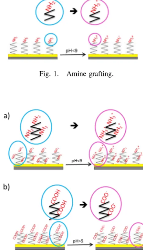
Several techniques (dry or wet pathway) lead to the modification of the surface properties, and more precisely the adhesive force, as a reactive ion etching process [8], the structuring [9] and the chemical compound adhesion. The common used methods, in liquid medium, are self-assembly monolayer (SAM) deposited [10] [11] or polymer adsorption. The most used materials in micro-systems are silicon or gold, so grafting [12] or polymer electrodeposited [13] are both easily implemented. Electrical charges of SAM or polymer can be controlled by the modification of the pH of the liquid medium [14], using the protonation or deprotonation of the amine or carboxylic function according to their own pKa (equilibrium constant) like shown on figure 1 and figure 2. This type of phenomenon as already been observed by Pollack and his team [15].
Fig. 1. Amine grafting.
Fig. 2. Substrate modified by amino (a) or carboxylic (b) function obtained by electropolymerisation.
Electrosynthesis of intrinsic conducting polymers as films on silicon or gold substrates is an interesting topic of
investigation. Indeed they have particular electrical properties and it’s possible to localise the deposit on a very small conducting area [16]. Moreover this method enables to obtain a greater charge density than those obtained with SAM (figure 1) [17]. Indeed the entanglement of the polymer chains allows a higher concentration of interest functions (amino or carboxylic function (figure 2)).
B. Force measurement
In order to characterize surface functionalisations, an atomic force microscope (AFM) has been used (figure 3). The silicon rectangular AFM cantilever has a stiffness of 0.3N/m. The cantilever is fixed while the substrate moves vertically. Most of the force measurement on AFM are done with the tip whose diameter is several tens on nanometers. In order to evaluate the interaction between a micrometer scaled robot and a substrate, the interaction between a mi-crosphere and a substrate has been considered. Consequently a borosilicate sphere (from 0.5 to 100µm diameter) has been glued on the cantilever. Force-distance curves were obtained by the exploitation of the measurement of the deformation of the AFM cantilever with a laser diode and a sensitive four-quadrant photodiode . Most of the measurements was performed at the driving speed of 200nm/s to stave off the influence of the hydrodynamic drag forces in 10 different points. All measurements were done in liquid medium with the pH necessary to protonate the chemical function of interest.
Fig. 3. The AFM-related setup used for force measurement.
III. MODELING OF THE ELECTROSTATIC FORCE
A. Modeling
Electrostatic interactions between charged surfaces in elec-trolyte solutions determine many dynamic phenomena like
Fig. 4. a) Pyrrole (Ppy) b) APTES ((3-Aminopropyl)triethoxysilane).
aggregation, suspension or adsorption to a surface [18]. The aim of this paper is to show that this kind of force could be used to manipulate small objects. A first coarse model considering only a surface charge has already been proposed by Dejeu et al. [14] in microrobotics. We are proposing in this paper a more realistic model. Indeed, the presence of a charged surface in an ionic solution induces a specific mod-ification of the medium. If the surface is positively charged, a digressive layer of anions appears around the contact with the surface until the back to the electric equilibrium in the bulk solution. This phenomena is called Electrical Double Layer (EDL). This EDL is modeled by the DLVO (Derjaguin, Verwey and Overbeek) theory based on the Guy-Chapman-Stern [19] model. EDL explains the behaviour between particles in colloidal suspension (figure 5), according to the Poisson-Boltzmann equation (PB) [20]. Indeed, two levels are noteworthy, the first one is the potentialψoat the surface
and the second is the potentialψdat the end of the compact
layer. Between these two values, the electrical potential decreases linearly [21]. Later, Adamczyk et al. established a numerical method to resolve the non-linear PB equation for sphere/plane configuration for applications associated with colloid particles adsorption [22].
Fig. 5. Schematic of electrical double layer (EDL) in a liquid in contact with a negatively charged solid by Stern modeling.
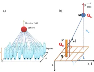
Fig. 6. a) Modeling of a dipole layer in interaction with a charged sphere b) Modeling in planar coordinates of a dipole in interaction with a charged sphere.
Our model shows the interaction between a charged sphere of 10 µm diameter and a substrate. According to the EDL model (figure 5), we modeled the solid substrate and the compact layer as a sum of dipoles and calculated the elec-trostatic force between this sum of dipoles and the charged sphere (figure 6a). The electrostatic force,δFelec, along the
vertical axisz opposed to an elementary charge δQsw on the
sphere is: δFelec= X ij δQsw. Qd 4πǫ0 .[(hw− k).M P− 3 2 − hw.M N− 3 2], (1) where Qsw and Qd are the sphere and dipole charge
respectively, hw is the orthogonal distance between the
charge of the sphere and the substrate, and k is the dipole thickness.M P and M N are the distance between the sphere and the top and the bottom of the dipole respectively. They are defined by equations (2) and (3) respectively:
M P =p(hw− k)
2+ (l.i)2+ (L.j)2,
(2) M N =ph2
w+ (l.i)2+ (L.j)2, (3)
wherel and L are the distances between two dipoles fol-lowing thex (vector i) and the y (vector j) axis respectively.
Total charge of the dipole is given by:
Qd= ncharges.e.l.L, (4)
wherencharges is the dipoles number on the elementary
surfacel.L and e is the electron charge.
The sphere has been numerized strip by strip (see in figure 7)
Fig. 7. Modeling of the strips of the sphere.
Thus the sphere elementary chargeδQsw is:
δQsw= ncharges.e.2π.rw.bw, (5)
wherew is the strip number,bw is the strip thickness and
rw is the radius of the disc at a hight of the stripw:
rw= rcosαw, (6)
whereαw is the angle of the stripw (see in figure 7).
So the orthogonal distance,hw, between the charge of the
sphere and the substrate is defined by:
hw= z + bw.(w − 1) +
bw
2 , (7)
where z is the distance between the bottom of the sphere and the substrate.
The total force Felec along z applied by the substrate on
the whole sphere is: Felec= X w δFelec, (8) or, Felec= X w X ij Qsw. Qd 4πǫ0 .[(hw− k).M P− 3 2 − hw.M N− 3 2]. (9) Consequently for all diameters spheres, the optimal num-ber of strips to consider on the sphere is a function of the distancez between the sphere and the substrate. Indeed when the sphere is far (z < r) from the substrate, 5 strips are enough to model the interaction whereas 5000 strips are necessary when the sphere is closed to the substrate (z < r/1000).
B. Simulation results
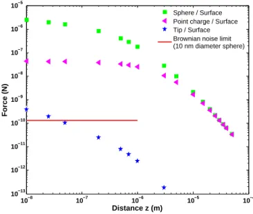
First results of this modeling are shown in figure 8. The lines correspond respectively to the interaction force-distance between the substrate and (i) a 10nm punctual tip (stars curve), (ii) a 10 µm diameter sphere considered as a point charge (triangles curve) and (iii) a numerized 10 µm diameter sphere with an all over distribution of charges (squares curve). 10−8 10−7 10−6 10−5 10−4 10−13 10−12 10−11 10−10 10−9 10−8 10−7 10−6 10−5 Distance z (m) Force (N) Sphere / Surface Point charge / Surface Tip / Surface Brownian noise limit (10 nm diameter sphere)
Fig. 8. Force-distance curves between a charged sphere or an AFM-tip and a surface of dipoles.
The model of the tip is closed to the colloidal behaviour of particles and is coherent with bibliography [23]. Indeed, the interaction force in colloids is less than 1 nN at few
nanometers distance as shown by Filby et al. [24]. Figure 8 shows that considering micrometer sphere increases signifi-cantly both the interaction distance and the interaction force. Indeed the use of a point charge on a 10µm diameter sphere instead of a point charge on a simple AFM tip of 10 nm multiplies the interaction force by 102
(crosses curve), and even103
when the charge is distributed on the sphere surface. Figure 8 illustrates also the differences between the two cases of sphere modeling: a point charge at the middle of the sphere (case 1) or a distribution of charges on the sphere surface (case 2). When the interaction distance is greater to 2 µm, there is no difference between the two cases. Whereas, when the distance is lower, a difference appears. It is due to the fact that some charges closed to the substrate, have a significant impact on the interactions. The repulsion force in the case 2 is ten times more than an unique charge at the sphere center, when the distance between the sphere and the substrate is 10nm.
C. Interaction distance
In order to evaluate the interaction distance of this force, we are going to compare it with the force induced by Brownian motion. Indeed, if the electrostatic force is greater than Brownian motion force, the behaviour of the sphere will be driven by the electrostatic force. If the electrostatic force is lower than Brownian motion force, the behaviour of the sphere is not influenced by the electrostatic force. We considered that the limit between the two cases define the interaction distance. The kinetic energy of Brownian motion EcB and due to the electrostatic force EcF are defined
respectively by: EcB= 1 2mV 2 b = 1 2kbT, (10) EcF = 1 2mV 2 F, (11)
wherem is the particle mass, VB is the Brownian average
speed and VF the speed induced by the force Felec, kb
the Boltzmann constant and T the temperature. During the sphere movement, the electrostatic force is equilibrated by the Stokes drag force:
Felec= 6πµrVF, (12)
whereµ is the dynamic viscosity of the medium and r the particle radius.
In order to determine the limit force where the Brownian motion is similar to the electrostatic force, we considered the case where:
EcF = EcB.
(13) By combination of (10), (11) and (12), the equation (13) becomes: m(Felec 6πµr) 2 = kBT, (14) where, m = ρ4 3πr 3 , (15)
whereρ is the sphere density.
Now, it is possible to define the limit forceFlimbetween
an electrostatic driven behaviour and a Brownian behaviour: Flim= s 27 ρ µ2π r kBT . (16)
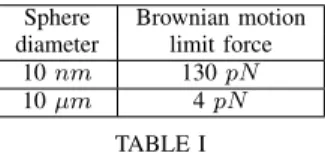
Numerical applications of this equation are given in table I. Sphere Brownian motion
diameter limit force 10nm 130pN
10µm 4pN
TABLE I
NUMERICAL APPLICATIONS OFBROWNIAN MOTION FORCE.
For a 10nm diameter sphere, the limit force is 130 pN . It represented by the green line on the left in the figure 9. The interaction distance is around 1 nm. For a 10 µm diameter sphere, the limit forceFlim is ten times smaller. It
is represented by the green line on the right in the figure 9. The interaction distance is now about tens of micrometers. Thus, it shows that electrochemistry is able to provide long range force on microspheres.
10−8 10−7 10−6 10−5 10−4 10−13 10−12 10−11 10−10 10−9 10−8 10−7 10−6 10−5 10−4 Distance z (m) Force (N) 10 nm 600 nm 1 µm 5 µm 10 µm 20 µm 40 µm 60 µm Brownian noise limit 10 nm 10 µm
Fig. 9. Abacus of force-distance curves according to several sphere diameter.
Figure 9 is an abacus of force-distance interaction in function of several sizes of spheres. It provides by the same model than in previous part (equation 9). From figure 9 and table I, a minimum sphere size is required to measure electrostatic interaction between a charged sphere and a charged substrate. Indeed in the case of a 10 nm diameter sphere, the electrostatic interaction is mostly covered by Brownian motion noise and makes it difficult to perform a precise force measurement.
IV. EXPRIMENTAL STUDY
In order to validate the impact of electrochemistry on the microsphere, different experimental studies have been carried. The first one is the measure of the repulsion between a substrate and a 10 µm sphere and the second one is the influence of the probe size on this repulsion.
Fig. 10. AFM with substrate in liquid medium.
A. Repulsive force measurement
The repulsive force measurement has been done between the borosilicate probe and a polypyrrole (Ppy) film. Polypyr-role (figure 4a) has been deposited on silicon covered by gold electrodes by electropolymerisation. Indeed, the used elec-trodes were parts of silicon wafer covered by 1µm sprayed chrome and gold to enhanced the conductivity and facilitate the electropolymerisation process. Ppy is a currently used intrinsic conducting polymer that chemical and mechanical properties have already been detailed by Patois et al. [25]. The measurements were done in liquid medium at pH 10 according to experimental conditions describe in section II and just after the film formation to avoid possible alterations (figure 11) with an AFM (figure 10).
The point 0 on the distance axis corresponds to the contact point between the cantilever and the substrate. The figure 11 shows that the interactions between the sphere glued on the cantilever and the substrate were strongly repulsive. Mean value of 5 µN with a maximum of 6 µN for the series of experimental tests with LiClO4 as the
counter-ion. This repulsion is due to the negative charge of the probe and of the film by the influence of the additional counter-ion tangled in the film (LiClO4 in this case). From
figure 8 and figure 11, it can be deduced that modeling and experimental works have the same order of magnitude with predicted and measured values of interaction force closed to the microNewton. Moreover the interaction distance is also similar between modeling with a predicted value of tens micrometers and experimental results with a measured result at 45µm. These experimental tests were performed ten times with a standard deviationσf of 0.38µN for the interaction
0 10 20 30 40 50 60 0 1 2 3 4 5 6 7 8 Distance z (µm) Normal force (µN) 45 µm 6,4 µN
Fig. 11. Force-distance curves on functionalised PPy in LiClO4 salt by
electropolymerisation in liquid medium (pH 10, spring constant 0.3N/m).
force and aσd of 4.24 µm for the interaction distance. So
we can conclude that these experiments are repeatable .
B. Study of the influence of the sphere size
In order to evaluate the influence of the sphere size, experimental studies have been carried. Substrate and spheres of several sizes from 0.5 to 100 µm diameter have been functionalised by grafting of APTES (figure 4b) [14]. Mea-surements of interaction force have been realized in liquid medium at pH 2 according to the equilibrium constant of amine function. The results are summarized in Table II.
Sphere Interaction Interaction diameter (µm) distance (µm) force (µN )
100 13.6 2.05 40 12.7 0.9 10 10.8 0.83 5 3.25 0.55 1 1.27 0.90 0.5 1.7 0.9 TABLE II
EXPERIMENTAL RESULTS FOR INTERACTION DISTANCE AND INTERACTION FORCE BETWEEN SUBSTRATE AND SPHERE
FUNCTIONALISED BYAPTES.
From Table II, the interaction distance increases from 1.7 µm to 13.6 µm with the sphere size. We also observed an increase of the repulsive force with the sphere size. So the sphere size has a influence on the interaction force and the interaction distance with the substrate. Repulsive force stays around the microNewton in each case. These results are quite consistent with previous modeling (figure 9), al-though a greater distribution of repulsive forces was expected between 0.5 and 10 µN .The repulsive distance determined experimentally are in accordance with the model exposed previously.
V. CONCLUSION ANDFUTURE WORKS
A. Conclusion
In this paper, we have studied interaction force and inter-action distance induced by electrostatic charges controlled by electrochemistry. Different functionalisations as grafting and deposition of intrinsic conducting polymer have been tested. All these techniques are promising ways to control electrostatic forces in non-contact microrobotics applications. Experimental measurements obtained with a relevant repeata-bility have been coherent results compared to the model. Some force up to 6 µm and interaction distance up to 45 µm have been observed experimentally on 10 µm diameter sphere. Chemistry appears as a promising way to improve micro-robotics efficiency and accuracy.
B. Future works
This approach could be implemented on a micro-robot, to validate the application context. For example, it might be adapted to the magnetic micro-robot MagPieR [26]. Electro-static levitation induced by chemical functionalisation could avoid the stick-slip effects and increases the repeatability and the speed of the micro-robot. Moreover this type of methods can be implemented in several materials (conductive or not), and thus it can be easily adapted to already developed micro-robots that can withstand the liquid medium and the required pH. Furthermore, the trajectory of the functionalised micro-robot could also be controlled by an external electrical field. Future works will also focus on the precise characterization of the charged substrate (surface, morphology, exact charge density, cristallinity). Moreover, it could be interesting to vary the ionic strength of the medium to evaluate the electric-field screening. It will permit to define the better medium to use to have the maximum charge available. Then, other PCIs or polymers have to be tested to make a comparative study and evaluate the better way of substrate modification for each micro-robotic application.
ACKNOWLEDGMENT
This work has been supported by Franche-Comt´e Region under FIMICAP (contract 2011C-07333), by the european project FAB2ASM (contract ”FoF-NMP-2010-260079”) by the Labex ACTION project (contract 11-LABX-01-01”), by the Equipex ROBOTEX project (contract ”ANR-10-EQPX-44-01”), by the French RENATECH network and its FEMTO-ST technological facility.
REFERENCES
[1] G. Fantoni and M. Porta, “A critical review of releasing strategies in microparts handling,” in Micro-Assembly Technologies and
Applica-tions, S. Ratchev and S. Koelemeijer, Eds. Springer US, 2008, vol.
260, pp. 223–234.
[2] M. Gauthier and S. R´egnier, Robotic micro-assembly. Wiley-IEEE Press, 2010.
[3] R. Bogue, “Assembly of 3d micro-components: a review of recent research,” Assembly Automation, vol. 31, no. 4, pp. 309–314, 2011. [4] C. Pawashe, S. Floyd, E. Diller, and M. Sitti, “Two-dimensional
autonomous microparticle manipulation strategies for magnetic mi-crorobots in fluidic environments,” Robotics, IEEE Transactions on, vol. 28, no. 2, pp. 467–477, 2012.
[5] B. J. Nelson, I. K. Kaliakatsos, and J. J. Abbott, “Microrobots for min-imally invasive medicine,” Annual review of biomedical engineering, vol. 12, pp. 55–85, 2010.
[6] M. Kharboutly, M. Gauthier, and N. Chaillet, “Predictive control of a micro bead’s trajectory in a dielectrophoresis-based device,” in
Intelligent Robots and Systems (IROS), 2010 IEEE/RSJ International
Conference on. IEEE, 2010, pp. 5616–5621.
[7] J. Dejeu, M. Gauthier, P. Rougeot, and W. Boireau, “Adhesion forces controlled by chemical self-assembly and ph: Application to robotic microhandling,” ACS Applied Materials & Interfaces, vol. 1, no. 9, pp. 1966–1973, 2009.
[8] J. Dejeu, M. Bechelany, E. Berodier, P. Rougeot, J. Michler, and M. Gauthier, “Nanostructured nonadhesive surfaces for micro- and nanomanipulation,” The Journal of Physical Chemistry C, vol. 116, no. 28, pp. 15 117–15 125, 2012.
[9] J. Dejeu, M. Bechelany, L. Philippe, P. Rougeot, J. Michler, and M. Gauthier, “Reducing the adhesion between surfaces using surface structuring with ps latex particle,” ACS Applied Materials & Interfaces, vol. 2, no. 6, pp. 1630–1636, 2010.
[10] S. Kivelson and A. Heeger, “Intrinsic conductivity of conducting polymers,” Synthetic Metals, vol. 22, no. 4, pp. 371–384, 1988. [11] U. Lange, N. V. Roznyatovskaya, and V. M. Mirsky, “Conducting
polymers in chemical sensors and arrays,” Analytica Chimica Acta, vol. 614, no. 1, pp. 1–26, 2008.
[12] E. Ruckenstein and Z. Li, “Surface modification and functionaliza-tion through the self-assembled monolayer and graft polymerizafunctionaliza-tion,”
Advances in Colloid and Interface Science, vol. 113, pp. 43–63, 2005.
[13] A. Cot, S. Lakard, J. Dejeu, P. Rougeot, C. Magnenet, B. Lakard, and M. Gauthier, “Electrosynthesis and characterization of polymer films on silicon substrates for applications in micromanipulation,” Synthetic
Metals, vol. 162, no. 24, pp. 2370–2378, 2012.
[14] J. Dejeu, P. Rougeot, M. Gauthier, and W. Boireau, “Reduction of a micro-object’s adhesion using chemical functionalisation,” Micro Nano
Letters, IET, vol. 4, no. 2, pp. 74 –79, june 2009.
[15] B. Chai, H. Yoo, and G. H. Pollack, “Effect of radiant energy on near-surface water,” The journal of physical chemistry. B, vol. 113, no. 42, p. 13953, 2009.
[16] T. Patois, B. Lakard, N. Martin, and P. Fievet, “Effect of various parameters on the conductivity of free standing electrosynthesized polypyrrole films,” Synthetic Metals, vol. 160, no. 19-20, pp. 2180– 2185, 2010.
[17] B. Coffey, P. V. Madsen, T. O. Poehler, and P. C. Searson, “High charge density conducting polymer/graphite fiber composite electrodes for battery applications,” Journal of The Electrochemical Society, vol. 142, no. 2, pp. 321–325, 1995.
[18] Z. Adamczyk, B. Siwek, M. Zembala, and P. Warszyaski, “Enhanced deposition of particles under attractive double-layer forces,” Journal
of Colloid and Interface Science, vol. 130, no. 2, pp. 578–587, 1989.
[19] D. L. Chapman, “Li. a contribution to the theory of electrocapillarity,”
Philosophical Magazine Series 6, vol. 25, no. 148, pp. 475–481, 1913.
[20] W. Bowen and P. M. Williams, “Finite difference solution of the 2-dimensional poisson-boltzmann equation for spheres in confined ge-ometries,” Colloids and Surfaces A: Physicochemical and Engineering
Aspects, vol. 204, no. 1-3, pp. 103–115, 2002.
[21] R. Parsons, “The electrical double layer: recent experimental and theoretical developments,” Chemical Reviews, pp. 813–826, 1990. [22] P. Warszyaski and Z. Adamczyk, “Calculations of double-layer
elec-trostatic interactions for the sphere/plane geometry,” Journal of Colloid
and Interface Science, vol. 187, no. 2, pp. 283–295, 1997.
[23] J. F. Joanny, L. Leibler, and P. G. De Gennes, “Effects of polymer solutions on colloid stability,” Journal of Polymer Science: Polymer
Physics Edition, vol. 17, no. 6, pp. 1073–1084, 1979.
[24] A. Filby, M. Plaschke, and H. Geckeis, “Afm force spectroscopy study of carboxylated latex colloids interacting with mineral surfaces,”
Colloids and Surfaces A: Physicochemical and Engineering Aspects,
vol. 414, no. 0, pp. 400–414, 2012.
[25] T. Patois, B. Lakard, S. Monney, X. Roizard, and P. Fievet, “Charac-terization of the surface properties of polypyrrole films: Influence of electrodeposition parameters,” Synthetic Metals, vol. 161, no. 21-22, pp. 2498–2505, 2011.
[26] S. Bouchebout, A. Bolopion, M. Kharboutly, I. A. Ivan, J. Agnus, and S. R´egnier, “Design and first experiments on magpier, the magnetic microrobot,” in Optomechatronic Technologies (ISOT), 2012