Development of Computational and Experimental Tools to
Study Mechanotransduction in C.elegans and Primates
by
Siddarth Kumar
B.Tech., Production and Industrial Engineering Indian Institute of Technology, Delhi (2004)
S.M., Mechanical Engineering,
Massachusetts Institute of Technology (2006)
Submitted to the Department of Mechanical Engineering in partial fulfillment of the requirements for the degree of
Doctor of Philosophy in Mechanical Engineering
at the
MASSACHUSSETS INSTITUTE OF TECHNOLOGY
MA SACHUSETTS INSTITUTE OF TECHNOLOGY
NOV 0 1
2011
LiBRARES
ARCHIVES
September 2011© Massachusetts Institute of Technology 2011. All rights reserved.
Signature of Author
Department of Mechanical Engineering September 1, 2011
Certified by
Dr. Mandayam A. Srinivasan Senior Research Scientist, Department of Mechanical Engineering Thesis Supervisor
Accepted by - ..; r
-Professor David E. Hardt Chairman, Department Committee on Graduate Students
Development of Computational and Experimental Tools to Study
Mechanotransduction in C.elegans and Primates
by
Siddarth Kumar
Submitted to the Department of Mechanical Engineering
on August 31, 2011 in partial fulfillment of the requirements for the degree of Doctor of Philosophy in Mechanical Engineering
Abstract
When an object comes into contact with the human fingertip, surface loads imposed on the fingerpad are transmitted to thousands of specialized nerve endings embedded in the skin tissue. These nerve endings, called mechanoreceptors, transduce the mechanical signals to generate a neural code of the incident stimuli enabling us to feel the object. The neural codes, generated by the spatial distribution of responding mechanoreceptors, are in the form of a temporal sequence of action potentials and tactile information is
encoded in the timing of each generated action potential. This thesis presents the development of predictive models to gain an understanding of the processes leading to mechanosensation. More specifically we study and model (1) how surface loads are transmitted to embedded mechanoreceptors and (2) how one type of mechanoreceptor (slowly adapting type-i or SAl) transduce these mechanical signals to a sequence of action potentials. We study these processes in two model organisms, namely the nematode C.elegans and the primate Rhesus macaque, each presenting its own advantages. Due to the physiological similarity of their anatomy and readily available mechanoreceptor neurophysiological data, primates are a popular model organism used to study the human tactile system. The study of the nematode
C.elegans provides us with the advantage of understanding the sense of touch at a molecular level.
To understand how loads are transmitted to embedded mechanoreceptors, it is essential to understand and characterize the behavior of underlying tissue. Most models in literature describing the primate fingertip use elastic models and compare the strain energy density at a mechanoreceptor location with the static steady state firing rate of the mechanoreceptor. We present experiments to measure the bulk viscoelastic properties of the primate finger tissue in vivo and non-invasively through a combination of single point indentation and numerical simulation. We develop, calibrate and validate realistic finite element models for the finger and use it to show that the stress relaxation of tissue surrounding the mechanoreceptor seems to regulate the dynamic firing rate of SA- 1 mechanoreceptors. We then present a point process model, based on the Pareto distribution, to predict the dynamic frequency of action potentials and compare our predictions with experimental data where the finger is indented with a flat plate.
In the last part of the thesis, we describe experiments to characterize the biomechanics of the nematode
C.elegans. Current models in literature describe the body of the nematode as a shell with internal
pressure. We propose a multilayer finite element model as an alternative to the shell model and show that it is better at predicting both force response data (obtained using AFM indentation) and surface deflection data due to indentation by a micro spherical indenter. Finally, we use the Hodgkin-Huxley model to predict the membrane potential of the PLM mechanoreceptor in C.elegans and compare our results with
experimental data in literature. Thesis Committee:
Dr. Mandayam Srinivasan (chair), ME Professor Roger Kamm, ME & BE Professor Mehmet Fatih Yanik, EECS
Acknowledgements
First and foremost, I would like to thank my advisor, Dr. Mandayam Srinivasan for his guidance and for giving me the freedom to work on any project I wanted to in the lab. During my stay at the Touch lab I have had the opportunity to work on diverse projects in different research areas; from the microfabrication of pressure sensors (during my masters), on virtual rehabilitation aids for the blind (between my masters and PhD) to my current PhD topic which is in biomechanics of touch. I have enjoyed working on all of the projects and I would have not had the opportunity to work on such diverse projects anywhere else so I am thankful for Dr. Srinivasan for hiring me back in the fall of 2004.
I would like to thank my committee members Prof Roger Kamm and Prof Mehmet Yanik for their valuable suggestions during our meetings and more importantly for being very patient with me. I have admired them and their work well before they agreed to be my committee and I am grateful to them for coming on board and helping me with my thesis.
I would like to thank Professor Carol Livermore and Professor Kripa Varanasi for hiring me as a TA for 2.001 when funding was a major issue for me. I thoroughly enjoyed working with them and the experience has given me a lot of appreciation for faculty who spend a lot of time behind the scenes preparing for a class which is not clearly evident when one attends a class as a student.
I would like to thank my colleagues at the MIT Touchlab; Dr David Schloerb, Dr. Gang Liu and Dr. Orly Lahav for their help and advise during each of my projects. It was a pleasure working with them.
I would like to extend a special thanks to Ms Leslie Regan, Ms Joan Kravit and the mechanical engineering graduate office as well as Ms Danielle Guichard-Ashbrook and the ISO office for their help during my stay here. Ms Regan is a wonderful person who has been unconditionally supportive throughout my stay here and I am indebted to her for that. Any graduate student (including me) from the mechanical department at MIT would say they would not have survived grad school at MIT meche without Leslie.
I would like to thank all my friends for making grad school life wonderful and entertaining outside lab as well: Mayank, Feras, Aparna, Gaggu, Kassu, Bhalla, Bijju, Vivek (kavi), Levi, Vikas, Bavand, Manohar, Vikram, Sangwan and many more.
Finally, I would like to thank my family for their unconditional support all through these years; my mother, Dr. Vanaja Kumar, and father, Prof TM Vinod Kumar, for having complete faith in me in whatever I chose to do. My elder brother Jaisurya and my twin brother, Dr. Srikant Kumar, for keeping me grounded in times of success and motivated in times of failure.
Table of Contents
Chapter
...
17
1.1 Background and M otivation... 17
1.2 The Human Tactile system... 20
1.3 Primates as a model organism ... 25
1.4 Biomechanical models of the primate finger ... 26
1.5 The nematode C.elegans as a model organism ... 33
1.6 T h esis O u tlin e ... 39
1.7 Contributions of this thesis... 41
Chapter 2: Prim ate Finger Biom echanics ...
43
2 .1 In tro du ctio n ... 4 3 2.2 Viscoelastic Characterization of Primate Skin Tissue ... 45
2.3 M ethods: Experimental Setup ... 47
2.4 Indenter Calibration... 48
2.5 Indentation Experiments and Results... 51
2.6 M odeling of viscoelastic response ... 56
2.7 Data Variability: M odel Fit Parameters for different fingers... 57
2.8 3D Finite Element M odels: Calibration and Validation... 60
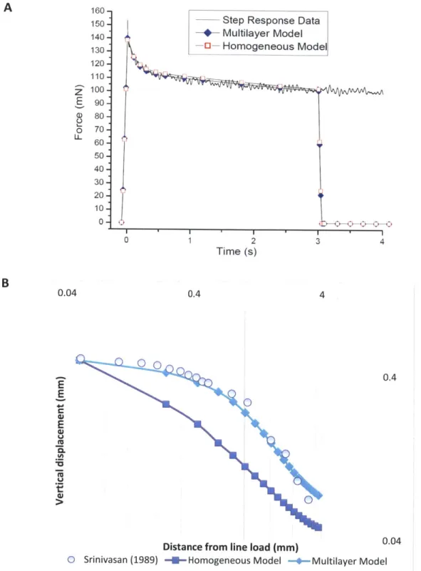
Chapter 3: Mechanoreceptor Neurophysiology Models ...
69
3 .1 In tro du ction ... 69
3.2 Flat Plate indentation and comparison to Neurophysiology Data... 71
3.3 Biological M odels of the Neuron... 73
3.4 Neural Spike trains as Point Processes... 80
3.5 Poisson model and the Pareto M odel ... 82
3.6 M odified Pareto M odel ... 90
Chapter 4: C.elegans Biom echanics ...
94
4.2 Force spectroscopy with an AFM apparatus ... 97
4.3 M aterials and M ethods ... 99
4 .3 .1 S train s ... 9 9 4.3.2 Cantilever calibration ... 99
4.3.3 Sample preparation ... 99
4.4 AFM indentation experiments and analysis ... 100
4 .5 M o d elin g ... 10 4 4.6 Analytic models... 106
4.7 Numerical models: 3D Hertz model, Shell model and the Multilayer model... 107
Chapter 5: The Shell model and the Multilayer model...115
5 .1 In tro du ction ... 1 15 5.2 Numerical Simulation of Indentation: Shell vs. Multilayer ... 118
5.3 Surface deflection experiments ... 120
5.4 Predicting neural response of mechanoreceptors using multilayered models... 124
Chapter 6: Conclusions ...
131
6 .1 S u m m ary ... 13 1 6 .2 F u tu re w ork ... 13 6
Bibliography ...
141
APPENDIX ...
149
Al. M ATLAB code to generate Poisson and Pareto based Point process model... 149
A2. M ATLAB code to compare parameters of a Pareto based Point process ... 152
A3. MATLAB code to generate Stimuli specific Pareto based Point process model... 156
A4. MATLAB Code to generate trace of surface deformation of the nematode C.elegans ... 160
A5. MATLAB Code to generate Hodgkin-Huxley model and fit to experimental data (O'Hagan et al, 2005)... 164
List of Figures
Figure 1.1 A schematic of a neuro-prosthetic device for amputees... 18 Figure 1.2 The four types of mechanoreceptors embedded in the skin. They are the Meissner corpuscles, the Pacinian corpuscles, Ruffini organs and Merkel Disks (from Neuroscience, 2003)... 2 0 Figure 1.3 The neurophysiological response of slowly adapting (SA) and rapidly adapting (RA) mechanoreceptors to force controlled ramp and hold stimulus. Responses to indentation with a flat plate and cylinders of different radii are also shown. (from Srinivasan and LaMotte, 1991).22 Figure 1.4 The Pacinian corpuscle (From Gray's anatomy of the human body (30th edition)).. 23 Figure 1.5 Nerve ending of Ruffini (From Gray's anatomy of the human body (30th edition)). 24 Figure 1.6 The "waterbed model" (A) shows a schematic of the waterbed model. (B) shows two hypothetical mechanoreceptors embedded in the incompressible tissue experience the same hydrostatic pressure due to an applied line load with force, F (C) shows the surface deflection profile of a primate and human finger matches well with that predicted by the "water bed" model. (Figures are adapted from Srinivasan, 1989)... 26 Figure 1.7 2D finite element model of the primate fingertip (A) shows the cross section of the cylinder model with a rigid embedded bone. Nodes at the bottom of the cylinder were
constrained to simulate the fingernail. (B) shows the surface deflection profile of the skin surface when indented with a line load. Experimental data is compared with numerical predictions including the cylinder and bone model (C) shows the comparison of experimentally recorded SA fiber spatial response profile (Phillips and Johnson, 1981 a) compared with spatial profiles of maximum compressive strain, absolute shear strain and strain energy density using he cylinder and bone model (Figures are adapted from Srinivasan and Dandekar, 1996)... 29 Figure 1.8 3D multilayer finite element model of the primate finger (A) shows three slices of the cross section of the 3D finite element model of the primate finger with realistic geometry. The inner most layer (black) is the bone and the outer four layers are tissues (B) shows the
comparison of the experimental surface deflection profile of the skin surface (Srinivasan, 1989) due to indentation with a line load with predictions of the 3D multilayer model. (C) shows the comparison of the neural response of SAL afferents to indentation with shaped step indenters (Srinivasan and LaMotte, 1987) with spatial profiles of strain energy density at a prospective
mechanoreceptor location (0.75 mm under the surface) are used to estimate the firing frequency (Figures are adapted from Dandekar et al, 2003) ... 30 Figure 1. 9 Mechanoreceptors in the nematode C.elegans ... 33 Figure 1.10 Comparison of mechanoreceptor potentials in C. elegans touch receptor neurons (A) and mammalian Pacinian corpuscles (B) (Goodman,2004). (B) taken from M. Mendelson, W. Loew enstein, Science 144, 554 (1964)... 34 Figure 1.11 (A) and (B) shows the setup used by Goodman et al (1998), O'Hagan et al (2005) for electrophysiological recording from PLM neurons in C.elegans in vivo (c) shows the
mechanoreceptor response (current and potential) of the PLM cell to a step force input. ... 34 Figure 1.12 (A) A general mechanosensory transduction model and (B) a proposed
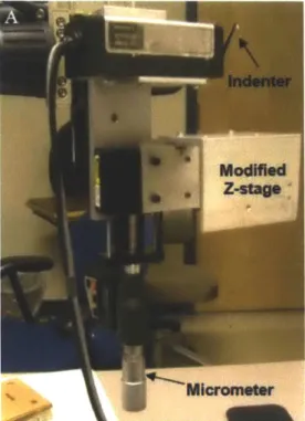
mechanotransduction channel model for the touch receptor in C.elegans (figure from Gillespie et al, 2 0 0 1) ... 3 8 Figure 2.1 Block diagram of the Indentation apparatus used for characterizing the viscoelastic properties of the primate fingerpad. The inset image shows the delrin probe tip used for the indentation experiments. The diameter of the flat end of the cylindrical indenter is 0.5mm. A typical input displacement stimulus and observed force output (shown qualitatively, not to scale). It is to be noted that the indenter was not glued to the primate finger during experiments;
however on retraction of the tip from the skin some adhesion was observed. ... 47 Figure 2.2 Position Calibration of the indenter (A) shows the setup used to determine the
position calibration constant (B) shows calibration plot of the measured voltage vs. the
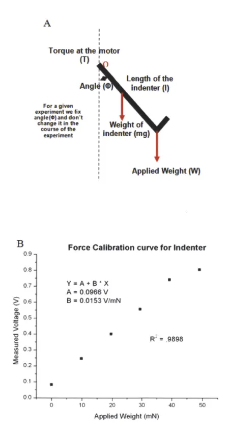
displacem ent of the indenter stage... 49 Figure 2.3 Force Calibration of the indenter (A) shows the schematic of the inverted indenter tip used to derive the force calibration constant and (B) shows calibration plot of the measured voltage vs. applied weight on the indenter... 50
Figure 2.4 Force response of the primate finger to static step indentation (A) shows 5 independent trials of the force response of the small finger to a static indentation of 0.8 mm superimposed to show repeatability (B) force response of the thumb of an anaesthetized primate to step inputs of 0.2 mm, 0.4 mm. 0.6 mm and 0.8 mm ... 53 Figure 2.5 Force response of the primate finger to static step indentation (A) and (B) shows the force response of the index and middle finger of an anaesthetized primate to step inputs of 0.2 m m , 0.4 m m . 0.6 m m and 0.8 m m ... 54 Figure 2.6 Force response of the primate finger to static step indentation (A) and (B) shows the force response of the ring and small finger of an anaesthetized primate to step inputs of 0.2 mm, 0.4 m m . 0.6 m m and 0.8 m m ... 55
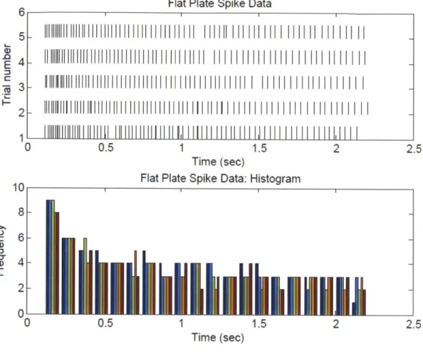
Figure 2.7 Model fit (A) shows a variation of the Maxwell-Weichert model comprising of three elastic springs and two purely viscous dampers. (B) shows the force response of the ring finger of the primate in response to a step input (displacement) of depth 0.6 mm and the modified M axw ell-W eichert m odel fit... 58 Figure 2.8 Model fits (A) shows the two exponential decay parameters for all 5 fingers and (B) shows the dimensionless coefficients, It is to be noted that each point represents a mean of n=19 readings taken across all 4 indentation depths (except for the index finger which includes only 10 successful parameters; see sec 2.3). The finger digits are defined as follows (1) Index Finger (2) Middle Finger (3) Ring Finger (4) Small Finger (5) Thumb... 59 Figure 2.9 The model fit (C) shows the mean quasi static force parameter Ao against indentation depth for all fingers. The error bars in all the plots correspond to ± one standard deviation. ... 60 Figure 2.10 (A) Cross section of the multilayer viscoelastic model built in ADINA showing the 4 layers of tissue (the innermost layer, the bone, is not shown) (B) the full 3D model which was used for simulating the indentation experiments. ... 62 Figure 2.11 Line load indentation (A) shows the model simulating the line load indentation experiment (B) shows the deformed mesh of the primate finger indented to 0.5 mm. after 3 sec o n d s... 6 5 Figure 2.12 (A) shows the model simulating a step indentation to a cylindrical tipped indenter similar to experiments performed in section 2.3 (B) shows the deformed mesh of the primate finger indented to 0.2 m m . after 1 second. ... 66 Figure 2.13 (A) shows the calibration curve used to estimate the viscoelastic properties of the primate finger model. Both the multilayer model as well as the homogeneous viscoelastic model could fit the force response data. (B) shows the surface deflection profiles of the calibrated multilayer model and homogeneous viscoelastic model showing that only the multilayer model is able to predict the surface deflection due to a line load as observed in experiment (Srinivasan, 1 9 8 9 ). ... 6 7 Figure 3.1 Flat plate indentation spike data. A flat plate was indented on the primate fingerpad to a depth of 0.5mm at a rate of mm/sec and held for 2 seconds and the neurophysiological response was recorded. (A) The plot shows data from 5 independent trials. Each action potential is
represented by a vertical line (B) shows the peristimulus time histogram (PSTH) of the data. Data is reproduced from Srinivasan & LaM otte (1991). ... 72 Figure 3.2 (A) shows the comparison of the strain energy density at a mechanoreceptor location with the average spike frequency (taken with 70 bins) vs. time. (B) shows the calibrated and validated multilayered model indented with a flat plate. The figure shows the effective stress at t = seco n d ... 7 4
Figure 3.3 Leaky integrate and fire model. (A) shows the circuit diagram of the leaky integrate and fire model. (B) shows the step input current given to the model (C) shows the response of the m odel to the step input. (from Lapicque, 1907)... 75 Figure 3.4 A schematic showing the circuit diagram of the Hodgkin-Huxley model. (from
H odgkin and H uxley, 1952)... 75
Figure 3.5 (A) shows the circuit diagram of the Freeman model (B) shows the input stimulus, assumed conductance function and the output response of the model. (From Freeman and
Jo h n son , 19 82 ) ... 7 7 Figure 3.6 A simulated spike train from a simple Poisson process with only one parameter (rate, k) generated in MATLAB. In this illustration, the rate (k) here is set to 30... 81
Figure 3.7 Simulated spike trains generated from different probability distributions. Spike trains are shown from the (A) Poisson distribution (B) the Pareto Distribution, (C) the Gamma
distribution and the (D) Inverse Gaussian distribution. The image is adapted from Kostal et al, 2 0 0 7 ... 8 3 Figure 3.8 Responses of the slowly adapting (SA) mechanoreceptor afferents to indentation (force controlled) by a flat plate and cylinders of different radii. Shaped indenters are pressed onto the fingerpad of a primate and held with constant force of 20 gm-wt for a period of 2 seconds. Data is shown for four independent trials with each indenter. The image is from
Srinivasan and Lam otte (1991)... 84 Figure 3.9 Responses of the slowly adapting (SA) mechanoreceptor afferents to indentation (displacement controlled) by a flat plate. A flat plate is pressed onto the fingerpad of a primate and held with constant displacement of 9 mm and held for a period of 2 seconds. Data is shown for twelve independent. The image is from experiments done by Srinivasan and LaMotte (1991).
... ... 8 5 Figure 3.10 A simulated spike train from a Pareto distribution with only two parameters (shape, a and threshold, u) generated in MATLAB. In this illustration, the u = 0.1 and a = 2... 87 Figure 3.11 Effect of changing the threshold parameter, a, in a Pareto based spike train. For all the simulations, the shape parameter, alpha is taken as 5 while the threshold parameter, a, is 0.1, 0 .5 an d 1 resp ectiv ely . ... 88 Figure 3.12 Effect of changing the shape parameter, alpha, in a Pareto based spike train. For all the simulations, the threshold parameter, a, is taken as 0.1 while the shape parameter, alpha, is 1,
5 an d 2 5 resp ectively . ... 89
Figure 3.13 Comparison of the Pareto based spike train vs. the simulated data... 92 Figure 3.14 Comparison of the Pareto based spike train vs. the simulated data... 93
Figure 4.1 (A) shows the piezoresistive cantilever system used by Park and coworkers to -estimate force curves for C.elegans (B) shows the linear force curve obtained using the system (C) shows the elastic shell model used in these studies to describe the observed behavior (figures A, B and C are from Park et al, 2007) (D) shows the "waterbed model" used to describe the biomechanical behavior of the primate finger (figure D from Srinivasan, 1989) ... 96 Figure 4.2 (A) shows a schematic of the atomic force microscope (AFM) setup used by Lin et al, to estimate the mechanical properties of rubber like materials (B) shows a set of typical force response curves from an AFM indentation experiment. In the figure, the two curves are shown
seperated for clarity. The top curve shows the reponse to indentation and the bottom curve shows the force response to retraction (figure from Lin et al, 2007)... 98 Figure 4.3 shows the deflection curve of the nematode. the y axis is the deflection of the
cantilever, d, and the x axis is the indentation of the piezo actuator.. ... 101 Figure 4.4 (A) shows the experimental d vs z curve for indentation with a worm (red curve) and a reference surface (black curve), glass (B) shows a schematic of linear force response of the the d vs. z curve for the worm and reference surface used to estimate the effective stiffness of the worm. kr is the slope of the force response curve of glass and kw is the slope of the force
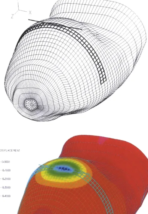
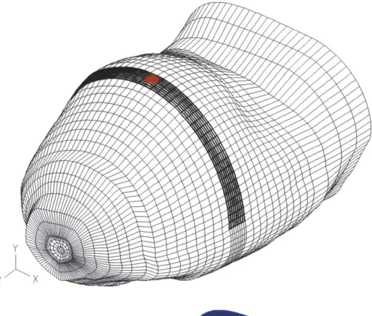
resp onse of the w orm ... 102 Figure 4.5 (A) and (B) show an electron micrograph of a cross section of the mid body of the worm. SW-Worm Viewer, Slice No.(315), 2005. Altun, Z. F. and Hall, D. H. In WormAtlas, (B) shows a close up of the section close to the surface showing the embedded nerve afferents in a layer between the cuticle and inner tissue. A scale bar was unavailable with the figure but the width of the worm is estimated to be around 50pm. (C) shows the proposed multilayer model used in this study consisting of a cuticle, mid and inner layer. ... 105
Figure 4.6 Schematic of the indentation experiment as well as the finite element simulation of th e ex p erim en t... 10 8 Figure 4.7 The force response of a corresponding Hertz model when indented with the same glass bead. The inset image shows the effective stress in the shell due to an applied indentation of 0.7 im. Our simulations matched with predictions from Hertz theory... 109 Figure 4.8 Simulation results to study the response of the stiffness curve to a change in material properties of the three layers. (A) shows the effect of hardening of the cuticle on the force response curve (B) shows the effect of softening of the mid layers on the force response curve. ... 1 I I Figure 4.9 (A) shows the effect of softening of the inner core on the force response curve of the worm (B) shows the process of linearizing the force response curve by manipulating the Young's Modulus of the three layers. The inset of(B) shows the final linearized curve with E1=50, E2=10 an d E 3= I M P a ... 1 12
Figure 5.1 (a) shows the linear force response of a 3D pressurized shell model to indentation with a glass bead of diameter 5 um. The inset image shows the effective stress in the shell due to an applied indentation of 1 m . ... 116 Figure 5.2 Indentation of the nematode with a micro needle showing the extent of deformation
of the cuticle and worm body is of order R (local deformation) as opposed to 6.6R as predicted by a shell m odel (de Pablo et al, 2003)... 117
Figure 5.3 (A) shows the surface deflection profile of a 100 ptm length shell and multilayer model indented with a 5 pm radii spherical indenter (B) and (C) show the deformed meshes of the multilayer model and the shell model. We show that for a multilayer model the deformation is local and for a shell it extends over a much larger length scale... 119 Figure 5.4 shows the setup used to characterize the surface deflection profile of the nematode. The setup consisted of a micro indenter mounted on an XYZ stage and a microscope fitted with a m icroscope and im age processing softw are... 120 Figure 5.5 (A) and (B) shows the boundary trace of the deformed and undeformed worm
obtained from the indentation experim ent. ... 122 Figure 5.6 (A) shows the comparison of the experimental surface deflection due to an applied spherical indentation of depth 6 um compared with the numerical simulation (B) shows the deformed mesh of the multilayer model used in the numerical simulation... 123 Figure 5.7 shows the computed strain energy density at a prospective mechanoreceptor location computed using the developed numerical multilayer model and a Boltzmann curve fit of the data. ... 1 2 8 Figure 5.8 shows the neurophysiological response of C.elegans in response to a force step as observed by O'Hagan and coworkers. The time course of the membrane potential and
mechanoreceptor current in response a force step is shown. Figure is from O'Hagan et al, 2005. ... 1 2 8 Figure 5.9 shows the step input current fed into the Hodgkin-Huxley model to estimate
membrane voltage compared with the experimental mechanoreceptor current measured in
response to a step force input (OHagan et al, 2005)... 129 Figure 5.10 shows the membrane voltage developed Hodgkin-Huxley model fitted to
experimental data of mechanoreceptor potential recorded from the PLM cells in C. elegans in response to a force step ... 129
Figure 6.1 (A) shows a DIC image of a typical culture of C.elegans embryonic cells 4 days after isolation and planting (Christiansen et al, 2002), Scale bar is 5 pim (B) shows a primary culture of C.elegans mechanosensory neurons (Bianchi et al, www.Wormbook.org) (C) shows cultured mechanosensory neuron expressing mec-4::GFP (Christiansen et al, 2002). Scale bar is 10 pm. ... ... ... 137
Figure 6.2 Methods of Mechanical Stimulation of mechanoreceptors. These membrane bound receptors can be exposed to uniform pressure using the setup shown in (a) They can be stretched by stretching the membrane they are bound to (b), a shear force can be applied to them by
exposing them to fluid flow either in a microfluidic channel or using a cone plate rheometer setup (c). We also plan to test the spatial resolution of receptors by using a probe to stimulate the film on which the receptors are bound (d). All figures have been adapted from Suresh (2007) and B ro w n (2 0 0 0 ) ... 14 0
Chapter 1
Introduction
1.1 Background and MotivationThe sense of touch, despite its prevalence and importance in our daily lives, is the least
understood of all the five senses. A loss of touch sensation can be debilitating and it
characterizes many disease states, it is found in patients affected by peripheral sensory
neuropathy caused by diabetes, tumors, toxins (for example arsenic and lead), autoimmune
responses (including HIV) and vascular and metabolic disorders. It is also a common occurrence
after physical trauma. Numbness of the lower limbs, which is a sign of loss of touch sensitivity, also characterizes Charcot-Marie-Tooth disease, a genetic disorder that debilitates more than
120,000 Americans annually. It is not clear if the loss of specific touch modalities can predict
these diseased states or perhaps give us more insight into the causes of these diseases. The
problem is compounded due to the fact that so little is known about how these cells operate and the protein machinery behind the cells.
The goal of this thesis is to develop a better understanding of the mechanisms of touch through
the development of a predictive multiscale model of the tactile system. More specifically, we
skin) is transmitted to specialized nerve endings embedded within the tissue and is transduced to electrical signals. A model that can predict the behavior of the mechanoreceptor is essential for developing state of the art neuroprosthetic devices. It was estimated that 1.6 million people lived
in the US with a loss of a limb in 2005 (Ziegler-Graham et al, 2008). In addition to this, each
year an estimated 158,000 persons undergo amputations (Dillingham et al, 2002). More recently, a study was conducted of all US casualties recorded in the recent conflicts in Iraq and
Afghanistan from October 1 2001 to June 1 2006. It was found that of the 8058 military
casualties meeting the listed criteria, 5684 (70.5%) were recorded as having major limb injuries. Of these, 423 (5.2% of all serious injuries; 7.4% of major limb injuries) underwent major limb
amputation or amputation at or proximal to the wrist or ankle joint (Stansbury et al, 2008).
However, in spite of the prevalence studies show that a large number of amputees do not use a prosthetic device. The documented rate of prosthesis use for upper limb amputation (ULA) is estimated to be as low as 27% (Wright et al, 1995) to 56% (Davidson J, 2002).
T 1. PRESSURE 2. DSP- based 3. Output Interface
0 Sensing of SENSOR Signal Processing System Circuit F
U pressure Pressure Transmission of E
C - Information based Information is synthesized neural ' E
H on prosthetic tc relevant neural converted to signal to relevant
circuit in the arm
touch signals L
We hope the models developed in this thesis will help improve current prosthetic devices by paving the way for the development of an integrated neuroprosthetic device, where an electronic version of the mechanoreceptor based on our models can be incorporated in prosthetic devices thus, in principle, enabling amputees "feel" through the prosthetic arm. A schematic of such a device is shown in figure 1.
1.2 The Human Tactile system
When an object comes into contact with the human finger, the interaction between the object and
the surface of the skin results in a load distribution across the surface of the fingerpad skin. This
load distribution is transmitted through the skin tissue to thousands of specialized sensory nerve
endings embedded within the human skin. These specialized nerve endings, called
mechanoreceptors, convert these incident mechanical signals into a sequence of electrical
impulses called action potentials. The information about the input stimulus is encoded in the
timing of these action potentials. The sequence of electrical impulses generated by the
mechanoreceptors is then sent to the brain, the interpretation of which results in us "feeling" the
object.
Meissner corpusce
Pacinian corpusde Ruffiiii organ Merkel disks
Epidermis
Dermis
Free nerve endings
Figure 1.2 The four types of mechanoreceptors embedded in the skin .They Pacinian corpuscles, Ruffini organs and Merkel Disks (from Neuroscience, 2003)
Though the human fingertip is innervated with thousands of mechanoreceptors, they can be divided into four types; Merkel disks, Meissner's corpuscles, Pacinian corpuscles and Ruffini's organs. Figure 1.2 shows a section of the human fingerpad showing each type of mechanoreceptor. These mechanoreceptors are also classified based on their behavior to a ramp and hold stimulus. Rapidly adapting mechanoreceptors (RA) respond only to the ramp phase of
the ramp and hold stimulus while slowly adapting receptors adapt respond both to the ramp and
hold phases of the input stimulus.
Figure 1.3 shows the response of slowly adapting and rapidly adapting mechanoreceptors to a
ramp and hold stimulus (force controlled). A flat plate as well as cylinders of different radii are
pressed against the fingerpad and held at constant force. The x axis represents time and each
vertical tick on the x axis represents an action potential. The neurophysiological response for 4
independent trials is shown next to each indenter. Slowly adapting mechanoreceptors include
Merkel Disks and Ruffini's corpuscles while rapidly adapting mechanoreceptors include the
Force 2 0 4 . 0.0 ime (svc) 2.2 flat JIllL . L________ .J-J_ 3 JIllL________________ 4 JILU L.1 1.. 2 ' *j ij.. I i r 2 JjL1J -I i III I R=/ n. 1 2 JilU LLiJLLLL I jjjj. . J I i I I I i
2 JAILLL WLLU-!] lULJjjIf
2 11||..1.I i I I-UHi .I 1 [ lI I I I I I I I 4 Jilltlli LLLLL11 1 1 -J 1 1 1 1 1 i 1 1
2 JIHUtllII ULl LUI I LJJ .LLLLLJLLi IJ I iiJ
4 J1iI1iIIWLl IIlL JJLllUUJJ LLIIL.l.IAiA.LLU. .U.J.
25 Force (gm-wl) f'at 3 4 R=1m-2 3 4 5 in I R=I/2 . I a 2n * 3 5 R=1/1(6 m, I 3 4 5 0 Time Isec1 22 list lilt lill lilt till Imi tooa oil I all AI Ell t si g
Figure 1.3 The neurophysiological response of slowly adapting (SA) and rapidly adapting (RA) mechanoreceptors
to force controlled ramp and hold stimulus. Responses to indentation with a flat plate and cylinders of different radii are also shown. (from Srinivasan and LaMotte, 1991).
Meissner's corpuscles are the most common sensory receptors of glabrous skin and account for
40% of all mechanoreceptors of the human hand. They innervate the human and primate
fingertip densely (150 per mm2) and have small receptor fields (Johnson et al, 2000). They reside
between the dermal papillae just below the epidermis. They are elongated receptors formed by a
connective tissue capsule comprising of several layers of Schwann cells. At the center of the
capsule there are one or more nerve afferent fibers that generate rapidly adapting action
potentials to stimuli. They are sensitive to low frequency vibrations (30-50 Hz).
Pacinian corpuscles make up about 10-15% of cutaneous receptors in the hand. They are large
encapsulated endings located deep in the subcutaneous tissue. They are onion shaped capsules
where the inner core is separated by the outer lamellae by a fluid filled layer. One or more nerve
afferent fibers lie at the center of the capsule. The capsule acts like a filter allowing only high
frequency disturbances to activate the nerve afferent. The Pacinian receptors are sensitive to high
frequency vibrations (250-350 Hz).
Nerve fiber Lainelae
Merkel's disks account for 25% of the mechanoreceptors in the hand. They are located at the
interface of the dermis and epidermis along the dermal papillae and innervate the skin quite
densely, about 100 per cm2 in the human and monkey fingertip (Johnson et al, 2000). They respond to sustained indentation and have small receptive field diameters. They are responsible
for sensing points, edges, shapes and rough textures. As compared to other mechanoreceptors,
Ruffini's corpuscles are not that well understood. They account for about 20% of the
mechanoreceptors of the human hand. They have elongated spindle shaped capsular structures
which are oriented parallel to and are sensitive to skin stretch.
Nerve Fibers
Connective tissue sheath
Figure 1.5 Nerve ending of Ruffini (From Gray's anatomy of the human body (30th edition))
As we can see from the above, the processes leading to tactile sensation in the hand is not trivial.
A simple task such as holding a cup of coffee in our hand and preventing it from slipping
involves thousands of tactile receptors (each of which senses a different type of mechanical
stimuli) sending a series of electrical impulses to the brain which instructs the muscles and
tendons in the hand to adjust accordingly based on what we feel. The role of the biomechanics of
skin tissue surrounding the mechanoreceptors cannot be understated. The loads that are
properties of the underlying tissue. The next section will focus on work done in literature to build
accurate biomechanical models of the finger to predict mechanoreceptor response.
1.3 Primates as a model organism
One of the first observations of an electrical response to mechanical stimuli in nerve cells was
made in the mid 1920s by ED Adrian (Adrian et al, 1926). Since then, a lot of progress has been
made in understanding the human tactile system. However, even today it is still not very clear exactly how these sensory cells operate. A lot more needs to be known about the behavior as
well as the components of the protein machinery that constitutes these touch complexes and their
roles in converting incident mechanical stimuli into ionic currents.
Due to the difficulty in studying such processes in humans, it is advantageous to use a model
organism where neurophysiological and biomechanical experiments are more feasible. Due to
the physiological similarity of its anatomy, primates are a popular model organism used to study
the human tactile system. Considerable work has been done in developing geometrically accurate
3D finite element models (elastic) of the primate fingertip to study tactile perception. We will
1.4 Biomechanical models of the primate finger
There has been a lot of progress in the development of accurate biomechanical models of the primate finger pad. Early models of the finger pad (Phillips and Johnson, 1981) idealized the finger to be an incompressible, homogenous, isotropic linearly elastic half space. The "waterbed model" (Srinivasan, 1989) assumed the finger pad to be an elastic membrane under pressure. Experiments were done to measure the surface deflection profile of the human and primate finger to a sharp wedge. The "waterbed model" was also indented with a wedge (line load) and an analytic solution of its surface deflection profile was estimated.
L i L:LL - L
MEMRANEMEMBRANEMMEMBRANE
-i -X -.
M1 Both mechanoreceptors sense the same
M2 hydrostatic pressure P I
DISTANCE FROM THE LOAD (mm)
050 500 F/ 00 0 o** C! MONWEY HUMAN 0 0 EXPERIMENTAL --- - "WATERBEC MODEL
P--.LIPS ANo JOwnson
Figure 1.6 The "waterbed model" (A) shows a schematic of the waterbed model. (B) shows two hypothetical mechanoreceptors embedded in the incompressible tissue experience the same hydrostatic pressure due to an applied line load with force, F (C) shows the surface deflection profile of a primate and human finger matches well with that predicted by the "water bed" model. (Figures are adapted from Srinivasan, 1989)
This model was successful in accurately predicting human and monkey fingertip surface deflection to line loads. However, the model does have some shortcomings. If we consider two mechanoreceptors, MI and M2 (figure 1.6B) embedded inside the "water bed" at different depths. For any applied load, P, both the mechanoreceptor will feel the same pressure P. There is no attenuation of mechanical signals with depth. Thus, these two mechanoreceptors should produce the same neural codes for the applied load. Thus, though the model was good in predicting the surface deflection profile due to an applied indentation with a line load, it could not be used to explain the transduction of mechanical signals into neural codes. There is a need for more mechanistic models to predict mechanoreceptor response.
Primate mechanoreceptor neurophysiological data is available in literature. Experiments done by Phillips and Johnson (1981 a) consisted of indenting a rectangular aperiodical grating (see figure 1.8 B) across the most sensitive spot of the fingerpad skin surface of a primate. During each indentation and recordings were made from individual peripheral nerve fibers from the ulnar and median nerves in the upper arm of the primate. The indenter was then moved laterally across and then indented again and so on. These experiments recorded the average steady state spike rate of the mechanoreceptors.
To address the shortcomings of the waterbed model, two dimensional finite element models of the monkey fingertip were developed (Srinivasan and Dandekar, 1996; Maeno et al, 1998). Figure 1.7A shows the 2 D finite element model developed by Srinivasan and Dandekar which consists of a rigid bone embedded inside a cylinder. The nodes at the lower end of the cylinder (figure 1.8A) were fixed to simulate the nail which was also glued during experiments and the
nodes near the top surface had a finer spatial resolution. An aperiodic rectangular grating, similar
PRESCRIBED DISPLACEMENT 1.00 mm 02.2 Cylinder bn. -06 Waewr 70
Dat. from Sriiva0(19211
0.0 1.0 2.0 3.0 4.0 0.1024 0.2.201 0.354 A 0.106. ... 0.140 -0.10 Fink*nc Gro Sb. oadimo 0.10 7 0.10 -eO 27 0.01 0.04 27 -24 -21 -18 -15 -12 -9 -5 -3 0 3 Spewia Location (MMn)
Figure 1.7 2D finite element model of the primate fingertip (A) shows the cross section of the cylinder model with a
rigid embedded bone. Nodes at the bottom of the cylinder were constrained to simulate the fingernail. (B) shows the surface deflection profile of the skin surface when indented with a line load. Experimental data is compared with numerical predictions including the cylinder and bone model (C) shows the comparison of experimentally recorded
SA fiber spatial response profile (Phillips and Johnson, 1981 a) compared with spatial profiles of maximum
compressive strain, absolute shear strain and strain energy density using he cylinder and bone model (Figures are adapted from Srinivasan and Dandekar, 1996)
Monkey M193, Materdal model: m43338 -0.5 F1.5 s0 40 Stop 3
For Stuuin Energ Density
-1 0 1 2 3 4
an. step 5
5 6 7 8
2 3 4 5 6 7 8
Spatial Location (mm.)
Figure 1.8 3D multilayer finite element model of the primate finger (A) shows three slices of the cross section of the 3D finite element model of the primate finger with realistic geometry. The inner most layer (black) is the bone and
the outer four layers are tissues (B) shows the comparison of the experimental surface deflection profile of the skin surface (Srinivasan, 1989) due to indentation with a line load with predictions of the 3D multilayer model. (C) shows the comparison of the neural response of SAl afferents to indentation with shaped step indenters (Srinivasan and LaMotte, 1987) with spatial profiles of strain energy density at a prospective mechanoreceptor location (0.75
In each indentation, a strain measure of interest at a fixed mechanoreceptor location was computed. Figure 1.8B shows the comparison of the recorded neurophysiological data of the SAl fibers (Phillips and Johnson, 1981) spatial profiles with three measures strain obtained from the 2D cylinder model. The maximum compressive strain (R 2=0.8 5), absolute shear strain
(R2=0.80) and the strain energy density (R 2=0.86) were found to match very well with the
neurophysiological static firing rate of data. The strain energy density and maximum
compressive stress emerge as the best candidates relevant to predicting SAl mechanoreceptor
response.
However, mechanoreceptors are oriented randomly within the skin tissue. If it is assumed that a particular receptor is able to measure strain in a fixed direction, then in order to measure the maximum compressive strain, the receptor should be oriented in a particular direction to measure
strain in the principle direction. The principle direction at a given location varies with the stimulus and thus a receptor fixed in its orientation cannot measure the maximum compressive
strain for all stimuli. The strain energy density in contrast is an invariant of the strain tensor and
does not depend on the direction of measurement at a given point and seems to be a better candidate to predict static mechanoreceptor response. When the model is indented with a line load to estimate the surface deflection profile due to the applied indentation, it was found that the 2D model was not a good fit with experimental data (Srinivasan, 1989). Thus, though the 2D model thus was successful in predicting static discharge rates of SA1 mechanoreceptors it was not able to match surface deflection data. There was a need to further develop models that were able to predict both these independent sets of data.
Dandekar et al (2003) developed a 3D finite element model of the primate finger with realistic
geometry. The model is shown in figure 1.8A. The five layered model consisted of an innermost
layer of bone followed by 4 layers of tissues whose mechanical properties could be varied. It was
found that a 3 layered model, where the ratio of the elastic modulii of the each of the layers were
10403:1:3:103:108 (where the last layer is the bone) was sufficient in predicting both the surface
deflection profile due to a line load (figure 1.8B) as well as the neurophysiological data of SAl
afferents due to indentation with shaped indenters (figure 1.8C). The material models used were
linear elastic for the skin tissue where a Poisson's Ratio of 0.48 was used (considering the tissue
to be incompressible). Again the strain energy density at the mechanoreceptor locations was
shown to be the likely strain measure coded by the mechanoreceptors.
The studies mentioned in this section enable us to model the behavior of the mechanoreceptor on
a micro scale using the primate as a model organism. The mechanoreceptor is assumed to be a
"black box" where mechanical signals go into the black box as an input and electrical impulses
act as the output. As has been mentioned earlier, the models developed here have applications in
developing state of the art neuroprosthetic devices that would enable amputees feel through a
prosthetic arm. However, to understand the relation of applied stimulation to its underlying
protein machinery (molecular scale) another model organism may be needed. As a second part of
this thesis we introduce a new model organism which shows promise in advancing the study of
1.5 The nematode C.elegans as a model organism
The roundworm C.elegans has emerged a popular model organism used by researchers the world over to understand various physiological processes in humans. The choice of this organism provides us with many advantages. As compared to the thousands of cutaneous receptors in mammals, there are only six nerve cells that govern light touch in C.elegans. The six mechanoreceptors responsible for light touch in C.elegans are Anterior Lateral Microtubules
(ALMR and ALML), Posterior Lateral Microtubules (PLML and PLMR), the Anterior Ventral
Microtubule (AVM) and the Posterior Ventral Microtubule (PVM). Three of these cells (ALML, ALMR and AVM) are known to be responsible for sensing touch in the anterior side of the nematode while two of these (PLML and PLMR) sense posterior touch. They are shown in figure
1.9.
nerve
axon/lateral
ning process PLMR
ALMR V
pharynx AVM LLsnpi ausPM
\synaptic
ALML branch
Figure 1. 9 Mechanoreceptors in the nematode C.elegans
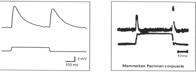
In vivo recordings of the electrical responses of two of these mechanoreceptor neurons (PLMR and PLML) near the worms tail (O'Hagan et al, 2005), have been found to be reminiscent of the
responses of Pacinian corpuscles in mammals taken about 40 years ago (Mendelson et al, 1964)
(refer to figure 1.10). This may suggest that there may be some aspects of mechanotransduction
Figure 1.10 Comparison of mechanoreceptor potentials in C. elegans touch receptor neurons (A) and mammalian
Pacinian corpuscles (B) (Goodman,2004). (B) taken from M. Mendelson, W. Loewenstein, Science 144, 554 (1964).
b) Gonad Stimulus probe Recording e,pipette
Figure 1.11 (A) and (B) shows the setup used by Goodman et al (1998), O'Hagan et al (2005) for
electrophysiological recording from PLM neurons in C.elegans in vivo (c) shows the mechanoreceptor response (current and potential) of the PLM cell to a step force input.
2mV
100 ms10ims
C.elegans is one of the first multi cellular organisms to be genetically sequenced. Because of the ease with which C.elegans can be genetically manipulated, there is a unique opportunity of linking specific genes to specific mechanical stimuli and physiological responses thus giving us insights into the relations between genetics, neurophysiology and mechanical response of these sensory units. Neurophysiology experiments are also more feasible with the nematode as compared to primates. Apart from the patch clamp method to measure membrane voltages in the nematode (Lockery and Goodman, 1998), methods have been developed to quantify neural activity by monitoring intracellular calcium changes in living nematodes through the use of an engineered genetically encoded molecule cameleon (Kerr et al., 2000; Miyawaki et al., 1997).
Though this thesis will not deal with the genetics of touch, a brief review of advances in constructing the mechanotransduction complex in C.elegans will illustrate the power of using this organism as a model to study tactile sensation enabling us to get insights that would not have been possible using only primates. Recent studies have identified genes responsible for mechanosensation in the nematode (Ernstorm and Chalfie, 2002). This was done by studying mutations that affect the development and function of the six mechanoreceptors in C.elegans. For example; if there is an observation of a loss in mechanosensory behavior of a mutant nematode, then mutations producing this phenotype tells us about genes needed for mechanosensory transduction or genes responsible for the development of mechanosensory cells or genes that are required for cellular interactions associated with the development of the mechanoreceptor (Chalfie et al, 1989).
It has been found that the six touch cells in C.elegans are affected by 18 genes. Most of these 18
genes are named "mec" or mechanosensory abnormal genes. The identified genes are mec-1 to
mec-10, mec-12, mec-14, mec-15, mec-17, mec-18, unc-86, egl-5 and lin-32. Out of these,
mutations in 13 of these genes (mec-1 to mec-10, mec-12, mec-14 and unc-86) result in complete
loss of touch sensitivity with few or no other abnormalities (Chalfie et al, 1989). Two other
genes (lin-32 and egl-5) result in loss in touch sensitivity only at the tail. The remaining genes
result in partial loss in sensitivity. Thus it appears that mutations in only 15 of these genes appear
to be required for complete touch insensitivity (Chalfie et al, 1989).
These genes have further been classified into three categories based on whether a mutation
affects the differentiation of the touch cell or its precursor (Chalfie et al, 1989). The first
category consists of genes that affect the precursors of the touch cells, more specifically;
mutations in these genes prevent the production of touch cells by affecting certain precursor cells
required for the production of the touch cells. Two genes fall into this category, namely, lin-32
ad unc-86. It has been observed that lin-32 mutants do not have PLM cells while unc-86 mutants
do not have PLM as well as ALM cells. A single gene namely mec-3 falls in the second category
that consists of genes that affect touch cells without affecting any other cells in the touch cell
lineage. The mec-3 mutants appear normal but the cells that should differentiate into touch cells
differentiate into some other types of neurons showing none of the characteristics of the said
All of the remaining 15 genes fall in a third category consisting of genes that affect only the function of the touch cells; mutations result in touch insensitive animals with differentiated touch cells. Mutations in five of these cells (mec-7, mec-12, mec-17, mec-1 and mec-5) result in a change in the morphology of the touch cells indicating that the morphological change results in the loss of function (Chalfie et al, 1989). Mutations in the remaining ten genes give non functioning touch cells without any difference in touch cell morphology. It has been found that three of these touch function genes (mec-1, mec-5 and mec-9) encode components of the extracellular matrix around the mechanoreceptor (Ernstorm et al, 2002) for example; the mec-5 gene encodes a collagen that is produced by surrounding hypodermis tissue (Du et al, 1996). The protein encoded by mec-9 is secreted by the sensory neurons and interacts with mec-5 and mec-4 (Gillespie et al, 2001). Two other functional genes (mec-7 and mec-12) encode a and
p
tubulins required for the formation of protofilaments microtubules which are observed within the structure of the mechanoreceptor (Ernstorm et al, 2002).Probably the most important component of the mechanotransduction complex is encoded by mec-4 and mec- 10. It has been observed that most mutations of mec-4 and mec- 10 render the animal insensitive to light touch (Gillespie et al, 2001). Both these genes encode transmembrane
ion channels proteins called degenerins. Degenerins are members of the DEG/ENaC (epithelial sodium channel) family of amiloride-sensitive ion channels which are membrane-bound ion-channel that is permeable to Lit-ions, protons and especially Nat-ions. Based on all these findings a molecular model for mechanotransduction complex in C.elegans has been proposed (refer to figure 1.12).
lExtracellular anchor (MEC-5)
Extracefllar anchorNE
Extracelular link
Transduction channel Extracellular link
(MEC-4, MEC-6?, (MEC-9)
Membrane MEC-lO)
Transduction channel
IntraceElular link Stomatin-like
MEC-2)
intaclluarlik
Somti-like
----Cytoskeleton
Microtubule (MEC-7, MEC-12) Figure 1.12 (A) A general mechanosensory transduction model and (B) a proposed mechanotransduction channel
model for the touch receptor in C.elegans (figure from Gillespie et al, 2001)
Section 1.4 covered advances in developing a biomechanical model for the primate finger to
study mechanotransduction. For C.elegans, no such computational model exists. It is essential to
develop a finite element model which can be subjected to the same controlled external loads as in
experiments and then study the internal stress state at various points in the cross section of the
nematode in response to this external loading. For this, information on the geometry as well as material properties of the nematode need to be ascertained.
1.6 Thesis Outline
The biomechanical models for the primate finger reviewed in chapter 1 assume the finger to be linearly elastic rather than viscoelastic. Furthermore, transduction models used to predict
mechanoreceptor action potentials do not take into account the viscoelasticity of surrounding
tissue and are more geared to predicting the static (steady state) firing rate rather than the
dynamic behavior observed in experiments. For the nematode C.elegans, no validated
biomechanical or transduction model exists in literature. This thesis aims to address these
shortcomings.
In chapter 2, we outline the development of a 3D viscoelastic finite element model of the primate
finger. First, we discuss biomechanical experiments done to estimate stress relaxation of
anaesthetized primate finger tissue non-invasively and in vivo. We then develop, calibrate and
validate of the 3D finite element model of the primate finger. Using this model, we show that the
viscoelasticity of the surrounding tissue plays a role in the dynamic firing rate of the
mechanoreceptor.
In chapter 3, we outline the development of a transduction model which is able to predict
dynamic mechanoreceptor firing rate. First, we review biological models of the neuron in
literature. A point process model based on the Pareto distribution is developed and used with the
calibrated and validated 3D finite element model to predict the dynamic firing rate due to
Chapter 4 and 5 deals with the development of biomechanical models for the nematode
C.elegans. In chapter 4, we discuss AFM experiments done to estimate force curves of the nematode as well as develop a multilayer finite element model of the nematode. In Chapter 5, we
compare the multilayer model with the "shell model" proposed in literature. First, we show
experiments to estimate the surface deflection profile of the nematode. We then show that a
multilayer mode is able to reproduce the linear force response as well as match the surface
deflection profile observed in literature while the shell model is not. Finally, a transduction
model based on the Hodgkin and Huxley neuron model was developed to predict C.elegans
1.7 Contributions of this thesis
We summarize the contributions of this thesis to the field of biomechanics as following: Primate Biomechanics:
1. A method to estimate viscoelastic properties of tissue in vivo and non invasively. We developed a method to estimate bulk material properties of the primate finger tissue in
vivo and non-invasively using a combination of biomechanical experiments (single point indentation) and numerical simulations (finite element modeling).
2. A calibrated and validated 3D viscoelastic finite element model of the primate
finger. We develop, calibrate and validate a 3D multilayer viscoelastic finite element
model of the primate fingertip. Our studies show that a multilayer model with an elastic
epidermis and viscoelastic core was sufficient to predict both surface deflection data and
force data. To our knowledge, no other viscoelastic model of the primate finger tip has
been published in literature.
3. A skin mechanics coupled transduction model that is able to predict dynamic
mechanoreceptor response of primate SA1 mechanoreceptor. Our studies show that
skin viscoelasticity plays a role in regulating the timing (dynamic) of SA 1 afferent
action potentials. Transduction models of the mechanoreceptor in literature (reviewed in chapter 3) do not take into account the viscoelasticity of the surrounding tissue. Further, nerve cell models in literature are geared towards predicting the steady state
mechanoreceptor response. We develop a novel point process model based on the Pareto distribution for SA1 mechanoreceptor transduction that was coupled with the 3D
viscoclastic model and was able to predict SAl dynamic neurophysiological response
C.elegans Biomechanics:
1. A method to estimate force curves for C.elegans using an atomic force microscope
(AFM). We adapt an atomic force microscope (AFM) for force spectroscopy to estimate
force curves for the nematode C.elegans. The only other method to estimate C.elegans
force curves in literature was done through the development of a piezoresistive force
transducer (Park et al, 2007). The force curves observed by us were also found to be
linear for our indentation ranges, similar to what was observed in literature.
2. A calibrated and validated 3D multilayer finite element model of the nematode. We
propose a multilayer finite element model of C.elegans as an alternate to the shell model
for predicting the biomechanics of the nematode. This is the first finite element based
model for the nematode in literature. We show that the multilayer model, like the shell
model, is also able to reproduce the linear force response observed in experiment.
Experiments were done to quantify the surface deflection profile of the nematode and we
show that the multilayer model was able to predict both the surface deflection profile as
well as the linear force response. The shell model on the other hand did not match the
surface deflection profile but was able to match the shell model.
3. A Hodgkin and Huxley based transduction model to predict C.elegans neural
response. We developed a mechanoreceptor transduction model based on the Hodgkin