HAL Id: hal-01118196
https://hal-ensta-paris.archives-ouvertes.fr//hal-01118196
Submitted on 18 Feb 2015HAL is a multi-disciplinary open access archive for the deposit and dissemination of sci-entific research documents, whether they are pub-lished or not. The documents may come from teaching and research institutions in France or abroad, or from public or private research centers.
L’archive ouverte pluridisciplinaire HAL, est destinée au dépôt et à la diffusion de documents scientifiques de niveau recherche, publiés ou non, émanant des établissements d’enseignement et de recherche français ou étrangers, des laboratoires publics ou privés.
Recent developments in femtosecond filamentation
Aurélien Houard, Yi Liu, André Mysyrowicz
To cite this version:
Aurélien Houard, Yi Liu, André Mysyrowicz. Recent developments in femtosecond filamenta-tion. Journal of Physics: Conference Series, IOP Publishing, 2014, 497, pp.12001. �10.1088/1742-6596/497/1/012001�. �hal-01118196�
Recent developments in femtosecond filamentation
A Houard, Y Liu and A Mysyrowicz
Laboratoire d’Optique Appliquée, ENSTA ParisTech, Ecole polytechnique, CNRS, Palaiseau, F-91762, France
E-mail: [email protected]
Abstract. We review recent developments in the field of femtosecond laser filamentation. 1. Introduction
We review recent developments in the field of femtosecond filamentation. In a first part, we describe the physical effects contributing to induce filamentation during the propagation of intense short laser pulses through transparent media. The importance of group velocity dispersion is illustrated in the case of fused silica. In the normal dispersion regime, the pulse evolution during propagation is complex and depends critically on input parameters such as the beam convergence, pulse duration, laser intensity. By contrast, a simple reproducible behavior is obtained in the anomalous dispersion region. The filamentary pulse is then closely parented to a lossy spatio-temporal soliton.
In a second part, we discuss the interaction between two air filaments in the normal dispersion regime. Interference between the fields of the crossing pulses leads to the formation of a plasma grating. We show how one can characterize the plasma density, its decay and the mechanism for this decay. Both ambipolar diffusion and plasma recombination play a role in molecules, whereas the decay is dominated by ambipolar diffusion in atoms. We show how energy can be exchanged between two crossing filaments due to scattering by a moving plasma grating. We also discuss the interaction between two counter-propagating filaments. The two filaments act as a retro-reflecting mirror: a third probe pulse of same frequency, incident at an arbitrary angle on this mirror, is retro-reflected with a spectacular improvement in beam profile quality and contrast ratio (ratio between precursor light and the pulse peak intensity).
In a third part, we discuss two applications making use of filaments in air. The first concerns the generation of THz pulses. A laser pulse undergoing filamentation emits a radially polarized THz pulse along a forward oriented cone. We discuss the origin of this effect and describe methods to enhance the THz emission by several orders of magnitude. This includes the application of an electric field, either static or optic, or the constructive THz emission from several filaments. The second application is the triggering of guided electric discharges by filaments and their use as RF antennas.
2. Filamentation in the normal/anomalous dispersion regime
Ultrashort, intense laser pulses are now commonly available, thanks to the development of laser-amplifiers systems based on Ti: Sapphire as the active medium and chirped pulsed amplification (CPA) technique. Pulses at 800 nm emitted by such lasers have typically a duration between 10 and 100 fs. A strongly non linear propagation regime sets in when such pulses, even with a modest energy of a few millijoules, are launched through atmosphere. This nonlinear propagation is complex and involves a subtle interplay between many effects. No analytical or semi-analytical treatment can be
used to describe it. One must resort to a numerical treatment. This is usually done by solving an extended non linear Schrödinger equation for the evolution of the pulse envelope treated as a scalar quantity. It allows a proper description in the paraxial approximation for rapid temporal changes, down to the single optical cycle limit, but fails to describe fast spatial changes, on a scale comparable to the wavelength. We refer to references [1, 2] for a description of the numerical code and its limits.
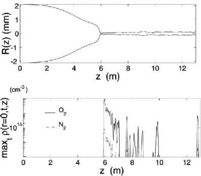
Figure 1. (a) Beam width of a collimated femtosecond laser pulses during filamentation propagation in air, obtained from numerical simulation. (b) The corresponding plasma density as a function of propagation distance.
Figure 1 shows the result of a simulation for the propagation in air of an initially collimated pulse of Gaussian profile (pulse duration: 100 fs, pulse energy: 5 mJ, beam diameter: 40 mm, wavelength: 800 nm). The first effect coming into play is the optical Kerr effect. It induces a change of the medium refractive index according to the law:
(1)
This leads to beam self focusing, because the index is larger around the beam center, where the intensity is highest, than on the wings and therefore bends the pulse wavefront. The effect is cumulative upon propagation because the focusing reinforces the change of n which in turn increases the intensity. This self focusing overcomes the defocusing effect of diffraction and leads to a collapse of the beam upon itself, if the initial pulse peak power exceeds a critical value Pcr [3-5] where
. (2)
In the example given, the initial region dominated by the optical Kerr effect extend over a distance of 6 meters at which point the beam diameter decreases abruptly and the pulse intensity increases correspondingly.
When the collapsing pulse intensity reaches a value above 1013 W/cm², multi-photon ionization of air molecules sets in. The creation of free electrons leads to a defocusing effect. Indeed, the refractive index decreases according to the law:
where is the density of free electrons and 2 2 0 0
me
e
c
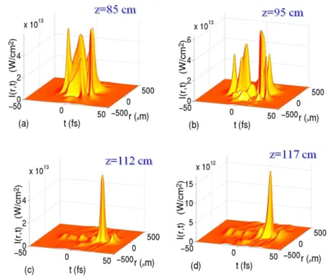
the critical plasma density above which the plasma becomes opaque (me and e denote the electron mass and charge). The plasma of highest density is created at the center of the beam and acts therefore as a defocusing lens. The combined dynamic interplay between beam self focusing and defocusing leads to the formation of a contracted pulse with an intense ionizing core that maintains a radius of ~ 50 µm over large distances. The filament core is surrounded by a reservoir of laser energy that sustains the core by supplying an inflow of energy. Figure 1(b) illustrates the action of the plasma. It surges and acts to prevent collapse when the pulse intensity reaches ~ 1015 W/cm². It first gives rise to a continuous meter long plasma string, followed by a quasi-periodic cycles of focusing and defocusing. At larger distances, plasma surges only intermittently. In the regions between and beyond these occasional surges of ionization, the nonlinear propagation is dominated by a dynamic competition between self focusing and diffraction (bright channels formation). It should be stressed that the behavior shown in figure 1 is not generic but depends on initial beam conditions (beam size and convergence, pulse energy, pulse duration, etc). With multi TW lasers, continuous plasma strings have been observed at a distance of 1 km with the plasma string extending over more than 50 m [6]. Bright channels persist over several km. [7-8]There is a profound restructuring of the pulse time profile during filamentation. Figure 2 shows the calculated evolution of an initial converging pulse with initial Gaussian profile upon propagation in Argon. A complex pulse splitting pattern takes place, which evolves during propagation and leads to the fortuitous emergence of isolated compressed pulses at certain distances. Pulses of initial duration 35 fs have been shown to compress down to 5 fs during filamentation in Argon [11]. It should be stressed again that the location and duration of such shortest isolated pulses depends on initial conditions.
Figure 2. Calculated evolution of an initial converging femtosecond pulse with initial Gaussian profile upon propagation in Argon.
A spectacular effect of filamentation is beam profile self-cleaning. It occurs in the region dominated by the Kerr effect, during the catastrophic collapse. The filament core acquires a Townes
mode profile that is retained in the bright channels emerging after the end of the ionization region [12-13].
We now address the influence of group velocity dispersion on the filamentation process. One can readily understand why it plays an important role. Consider the evolution of the pulse spectrum in the self-focusing region. Because of self-phase modulation [14], instantaneous frequencies are created that shift to the red (blue) the ascending (descending) part of the pulse, according to the following formula:
2 0 0
( , )
( )
t
n
z
I r t
t
c
t
. (3)In the normal dispersion region, red frequencies move faster than blue frequencies and therefore there is a detrimental pulse stretching during propagation. In the anomalous dispersion region, by contrast, red frequencies have a slower velocity than blue components. The generated frequencies are swept back to the main pulse. As a consequence, one expects lower threshold for filamentation and more stable filamentary pulses in the region of negative group velocity dispersion (GVD).
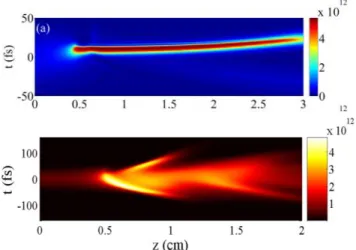
Figure 3. Numerical calculation of the pulse evolution during
filamentation in silica for a femtosecond pulse with a central wavelength at 1.6 µm (a) and at 800 nm (b).
Experimental verification of the role of the dispersion regime would be difficult to achieve in gases, because of the lack of extended regions of negative group velocity. Transparent solids such as fused silica offer a compact system where it can be experimentally verified [15]. Indeed, there is a wide frequency range of anomalous dispersion starting around 0.97 µm and extending beyond 3.85 µm in SiO2. The critical power in SiO2 is a few MW instead of GW for gases. Figure 3 shows a comparison between the calculated filamentation in both dispersion regions. With positive GVD, the behavior is complex, showing complex pulse breaking, analog to what happens in air. With negative GVD, a single compressed pulse is formed after 0.5 cm of propagation. The slightly subluminal pulse then conserves its diameter and duration over the remaining length of the 3 cm thick sample.
Figure 4. Side photography of the blue fluorescence of SiO2 induced by a self-guided laser pulse at 1.9 µm with P = 30 Pcr. The laser pulse is focused on a 70 µm spot (FWHM) at the left surface of the 3 cm thick sample.
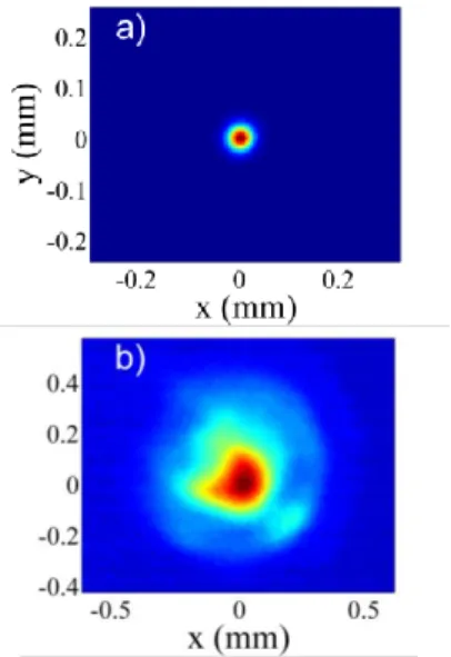
Experiments confirm these simulations. Figure 4 shows a side image of the blue luminescence emitted by the sample at high intensity I >1013 W/cm². The 20 µm wide filament is formed after 0.5 cm and is maintained over the rest of the sample. Figure 5 compares the beam profile emerging from the sample to the profile measured at an equivalent distance in the absence of sample. Pulse self cleaning, a signature of filamentation is manifest, as well as beam contraction. Measurement of pulse duration of the pulse exiting the sample is shown in figure 6. In agreement with the numerical simulations, the pulse contracts in time and keeps the contracted value over the sample length. From the numerical calculations, one deduces that the filament core has a duration of 8 fs. Together with its surrounding reservoir, the pulse duration becomes 25 fs, in agreement with the measurement where the central core and its reservoir are not resolved. Thus, the filamentation process in the anomalous region leads to the formation of a pulse that is almost invariant with propagation and is therefore closely parented to a spatiotemporal soliton. It must be underlined however that the pulse is lossy since the pulse consumes energy to ionize the medium. Also, part of the light energy is dissipated in the form of a conical emission. [16]
Figure 5. Beam profile of the laser pulse at 1.9 µm (a) with filamentation and (b) without filamentation in the fused silica sample. Intensity scale is normalized.
Figure 6. Measurement of the 1.9 µm pulse temporal shape after propagation in the sample performed with a WIZZLER. 3. Interaction between two filaments
Interaction of filaments has been observed to give rise to many interesting phenomenon such as energy exchange between filaments, enhanced third harmonic [17-19], plasma grating formation [20-22], molecular lensing effect [23], coherent control of filament fusion or repulsion [24-25], etc. In the following we discuss several aspects of the interaction between two filaments that enable to extract properties of the plasma created during filamentation, to exchange energy between crossing filaments and to improve spectacularly a third pulse probe pulse of same wavelength.
3.1. Plasma grating
3.1.1. Temporal dynamic of a plasma grating. Field interference of two crossing filamentary laser
pulses give rise to laser intensity spatial modulation in the overlapping area. As a result, a strong modulation of the plasma density is created due to the highly nonlinear nature of optical ionization. This modulated plasma structure, i.e. plasma grating, is formed instantaneously, on the time scale of the pulse duration p. On the other hand, its subsequent decay is long and can last for several hundreds
of picoseconds in atomic gases. It is important to analyze this decay in view of possible applications. Recently, we measured the decay process of the plasma grating in different molecular and atomic gases. In the experiment, we employed a probe pulse at 400 nm co-propagating with one of the pump pulse. This 400 nm probe pulse is expected to be diffracted into the propagation direction of the other pump pulse in the presence of the non-sinusoidal plasma grating. Therefore, the measured 400 nm signal as a function of the temporal delay between the probe pulse and the two synchronized pump pulses allows characterizing the temporal evolution of the plasma grating. More details of the experimental setup can be found in ref [26]
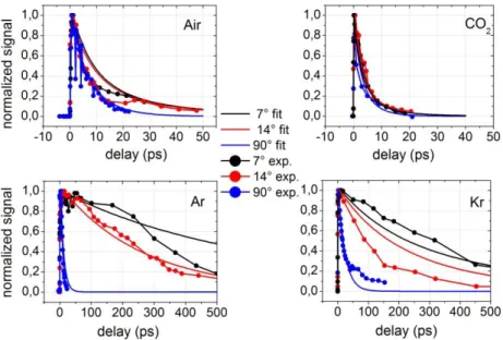
It was found that in molecular gases like N2 and O2 the plasma grating decays rapidly, with a lifetime about 10-20 ps (Figures 7(a) and 7(b)). However, in atomic gases such as Ar and Xe the plasma grating persists for more than 300 ps (Figures 7(c) and 7(d)). The decay of a plasma grating process is expected to be due to free electron recombination and ambipolar diffusion. To obtain insight on the respective importance of the two effects, we varied the crossing angle of the two pump pulses. The resulting variation of grating period leads to a change of the ambipolar diffusion while the free electron recombination remains the same. From such experiments, we conclude that the grating evolution is ruled by ambipolar diffusion in atomic gases and by a combination of ambipolar diffusion and collision-assisted free electron recombination in molecular gases. From the systematic measurements, electron diffusion and recombination coefficients are extracted for Ne, Ar, Kr, Xe, N2, O2, CO2 and air at 1 bar [27].
Figure 7. Normalized intensity of diffracted probe signal as a function of the delay (ps) for crossing angles of 7°, 14° and 90° in different gases (Air, CO2, Ar and Kr). Measurements are represented by dots. Calculations are represented by solid lines.
3.1.2. Energy exchange between filaments in the presence of travelling plasma grating. The first
experimental observation energy exchange between two filaments was reported in 2009 by Bernstein
et al. [28]. They demonstrated an energy exchange ratio of 7% between two filament-forming pulses
with slight frequency difference. In their work, a travelling refractive index grating is formed due to the Raman effect of air molecules. As a result, the classical two-beam coupling (TBC) scheme applies [28-29] and laser energy transfers from the high frequency pulse to the low frequency pulse. This provides a control over filaments propagation by modifying their characteristics in flight.
Recently, we observed a new regime of energy exchange where laser energy transfers from the low frequency pulse to the high frequency one. This new type of energy exchange was also found in monatomic noble gases such as Ar and Xe, excluding a traditional TBC mechanism based on a retarded optical Kerr nonlinearity. We attribute this new energy exchange to the effect of a moving plasma grating formed at the crossing point of the two filamentary pulses. Due to its plasma nature, this refractive grating can sustain very high laser intensity. With tightly focused laser pulses, we have demonstrated energy exchange efficiency of 50% in air. The result is presented in figure 8 [22].
Figure 8. Energy exchange between two filaments crossed with an angle of 20º.
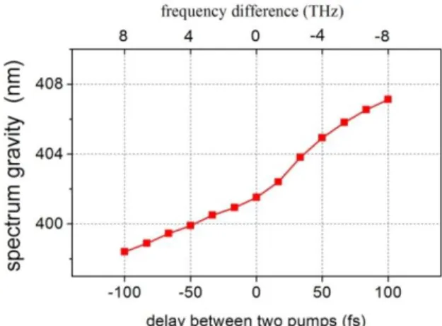
3.1.3. Plasma grating in motion. To detect the movement of a plasma grating, we employed an
experimental setup similar to that in 3.1.1. except that there was a difference in the wavelength of the two pump pulses [30]. We spectrally analysed the diffracted 400 nm pulse with a spectrometer. The movement of the plasma grating imparts a frequency shift on the probe pulse owing to the Doppler effect. Figure 9 presents the spectrum gravity of the reflected 400 nm signal pulse as a function of the time delay (frequency difference) between the two pump pulses with linear chirp. The central frequency of the signal pulse shifts proportional to the frequency difference between the pump pulses, i.e., to the velocity imparted to the grating. A calculation of the measured frequency shift based on the classical Doppler effect agrees well with this result [30].
Figure 9. Spectrum center of gravity of the signal pulse as a function of the time delay between the two pump pulses.
3.2. Filaments mirror
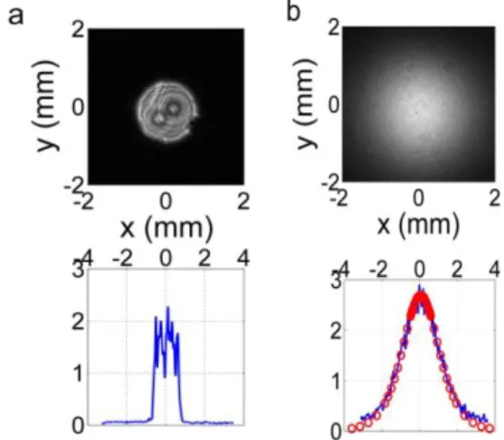
A special geometry is obtained when two filaments meet head on [31]. The encountering filaments form a mirror to a third probe pulse of same frequency impinging at an arbitrary angle. The mirror has special properties because the reflection occurs in the retro-direction. In addition, the reflected beam profile and pulse contrast ratio is dramatically improved. Figure 10 shows the beam fluence profile of the probe pulse before and after reflection. One can understand this spectacular property by considering the plasma grating formed by either pump with the probe pulse. As shown in section 3.1.1, the other pump will diffract into the direction of the incoming probe. Therefore, the reflected pulse is replaced by a fraction of the pump pulses with self-cleaned beam profile. The profile fits indeed a Townes mode profile, as expected if the retro-signal corresponds to a diffraction from the filaments. In addition, the small size (4500 µm3) acts as a pulse cleaner removing distortions in the phase profile of the incoming probe pulse.
Figure 10. Fluence profile of a femtosecond pulse before (a) and after (b) reflection on the filament mirror, as recorded in a single shot with a CCD camera.
Figure 11. Reflectivity as a function of the pump pulses energy. Probe pulse has energy of 160 and 340 µJ and is incident at an angle of 90°. The three pulses are coincident in time. Figure 11 shows the reflection of the filament mirror as a function of pump laser intensity for a probe incident at 90° from the filaments. Before the onset of ionization, the reflection is very small, because no plasma grating is present. There is a very steep increase of the reflection once the threshold for pump beam filamentation is reached, due to the high-order dependence of the ionization rate with intensity, followed by a near saturation, with a reflection efficiency of 20-30%, reflecting the intensity clamping inside a filament [1]. At an incident angle of 30°, the reflection increases to 40%.
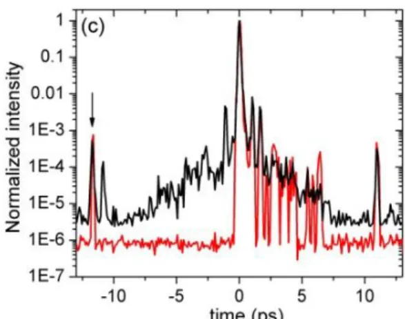
This leads to the possibility of temporal pulse cleaning by removing light precursors. Indeed, if the chronology of the pump and probe pulses is adjusted such that they all meet at the same time, any precursors present in the pump and probe pulses will not be reflected because no plasma mirror is formed at the time of their encounter, due to the corresponding lower intensity. The time profiles of the incident and retro-reflected pulse have been measured with a third order -2 cross-correlator. No precursor was detected in the reflected pulse within the dynamic range of the detector, as shown in figure 12.
Figure 12. Temporal contrast of the probe (in black) and of the reflected beam (red) measured with a third order cross correlator.
4. Applications of femtosecond laser filaments
Intrigued by the spectacular effects accompanying filamentation process, researchers have demonstrated plenty of scientific applications of the filaments such as triggering and guiding of lightning [32], Light Detection and Ranging Technique (LIDAR) [33], few-cycle light pulse generation [34], virtual antenna [35], micromachining in transparent solids [36], Terahertz (THz) pulses generation [37], control of aerodynamic flows [38], water condensation [39] and snow formation [40]. Some applications such as few-cycle pulse generation are already quite matured, while others like THz generation have just been discovered and require further investigation. In the following two sub-sections, we will detail two applications: THz wave generation by filaments and control of electric discharges with filaments.
4.1. THz generation by one filament, two filaments
In 2007, D’Amico et al. reported a forward THz pulsed radiation stemming from a femtosecond laser filament in air [37]. They observed that the THz is radiated in a hollow-cone structure in the laser propagation direction, with a radial polarization (see figure 13). The authors developed a Transition-Cherenkov model which reproduced the above observed features [41]. In this model, the heavily damped longitudinal plasma oscillation produced in the wake of the propagating pulse is at the origin of the THz pulsed emission. Terahertz (THz) radiation produced by ultrashort laser pulses in air attracted much attention in recent years, since it has some unique properties. The THz source can be positioned at the proximity of a remote target by displacing the onset of filamentation. This solves the long-standing problem of the poor propagation of THz through atmosphere due to strong absorption by water vapor. In contrast to other THz generation techniques with short laser pulses, there is no obvious limit to the laser power that can be used, since there is no material in the path of the pulse that can be damaged.
However, the energy conversion efficiency from laser to THz radiation by a single filament is low, on the order of 10-9 [42]. Therefore, it is desirable to improve the conversion efficiency and control the physical properties of this Terahertz radiation. Several techniques have been developed along this line. In a first scheme, an external electric field is applied on the filament either longitudinal or transverse. A THz enhancement by 3 orders of magnitude is obtained with an applied field Eext ~ 10
kV/cm (figure 13). At the same time, the radiation pattern and polarization property of this amplified emission keep the same as that of the pure transition-Cherenkov THz radiation [43]. This amplified THz pulse is of particular significance since a radially polarized THz wave has been demonstrated to be compatible with the propagating mode of a metal wire THz waveguide [44]. Although, this method
of enhancement suffers from the fact that the electric field must be applied on the plasma region of the filament, not an easy task for stand-off THz applications.
Figure 13. Amplification of the transition-Cherenkov THz emission. The pure transition-Cherenkov THz (Eext = 0 kV/cm) is multiplied by a factor of 200 for visibility.
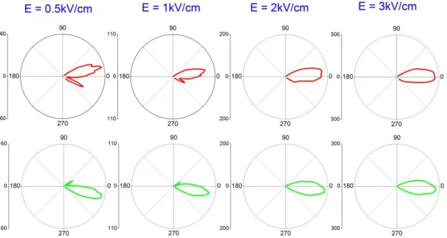
For most THz applications, a THz beam with maximum intensity on the axis is preferable. This requires the presence of a transverse current in the filament and an orthogonal electric field should be able to fulfill this task. In the experiment, we applied an external electric field perpendicularly to the filament axis. With the increase of the external electric field strength, the asymmetrical radiation pattern becomes more and more symmetrical (figure 14). As a result, a THz beam with above desired feature was obtained when Eext exceeds 3 kV/cm. More important, the THz intensity was enhanced by
3 orders of magnitude with respect to the transition-Cherenkov THz with Eext = 9 kV/cm. Concerning
the THz polarization, we found it is linear polarized and the polarization plane is dictated simply by the direction of the external field. In addition, we demonstrated that the polarity of the THz can be easily controlled by the direction of the electric field [45].
Figure 14. THz Radiation pattern from a laser filament in the presence of increasing transverse electric field. In the top (bottom) row, the external electric field is directed downward (upward).
Another approach is to use an oscillating transverse field, by combining a short IR pulse at 800 nm with its harmonic generated in a thin BBO crystal. After the first demonstration of this two-color method [46], it has been extensively studied with a millimeter scale long filament (L ~ THz) [47-52]. It was found that the optical biased at second harmonic frequency can lead to a THz amplitude enhancement by two orders of magnitude compared to the air plasma driven by just 800 nm femtosecond laser pulses [47, 49]. The relative phase between the fundamental laser field and its second harmonic was found to be critical for the yield and polarity of the THz radiation [47, 53]. Recently, this method was also extended to long air plasma (L >> THz) obtained in the filamentation regime [54-55]. For such long filaments, it was confirmed that the two-color scheme is more efficient than just a pulses at 800 nm. But, the temporal separation of the 800 nm and 400 nm pulses during their propagation inside the long filaments due to group delay dispersion of air sets a limit of interaction length (~ 2 m) and results in a strong THz yield decrease for standoff THz generation [55]. One advantage of the filaments-based THz source lies in the fact that it is laser damage-free due to its plasma nature, and one can expect high energy THz radiation with powerful incident femtosecond laser pulses. However, it is well known that multiple filamentation forms when the incident laser power well exceeds the critical power for self-focusing in air Pcr (~ 5 GW [1]). The underlying mechanism of multiple filamentation is the imperfection of the laser beam spatial profile as well as the turbulence in air during propagation. As a result, the process of multiple filamentation changes from shot-to-shot, which hinders the usage of multiple filaments as a stable THz source. Is there possible solution?
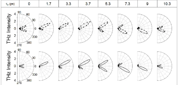
Inspired by the phased antenna array in the RF domain, we recently proposed and demonstrated experimentally the coherent synthesis of THz radiations of an array of organized filaments [56]. We find that the THz intensity scales up with N2 provided that proper filament separation and laser pulse time delays are chosen. Moreover, the THz radiation pattern can be controlled, which is a useful property for many applications. For example, in figure 15 we presented the THz radiation patterns obtained from two filaments separated by a distance of 2.4 mm for increasing time delay between the two pulses. Upon increase of the delay p, the radiation pattern becomes asymmetric. Withp = 3.7 ps, the radiation is totally directed along one lobe. This is particular interesting for applications where irradiation of targets with intense laser pulse should be avoided. Our simulations based on the Cherenkov-Transition model reproduced well our experimental observations.
Figure 15. Evolution of emission diagrams of the THz radiation from two neighbouring filaments as a function of the temporal delay between the two laser pulses. The two filaments
We further extrapolated the simulation to a higher number of filaments. We have calculated the THz radiation distribution for N = 4, 6, 8, 9, 12, 16 filaments organized in a square grid. With a properly optimized delay, the total THz energy can be channeled towards a preferential direction. With two filaments and zero delay, a butterfly wing pattern appears in the XOZ plane (figure 16 (a)). A single leaf radiation pattern is obtained with p = 3.5 ps (figure 16(b)). For a larger number of filaments, similar leaf-shape radiation pattern appear with properly chosen pulse delays, as presented for 16 filaments in figure 16(c), where its peak intensity is found to be ~ 250 times that of a single filament.
Figure 16. Calculated THz radiation diagram from two parallel filaments separated by 2.4 mm without time delay (a) and with a time delay p = 3.5 ps (b). (c) Calculated THz radiation diagram from 16 filaments with proper time delays.
4.2. Control of electric discharges with laser filaments
Plasma strings produced by femtosecond laser filaments proved to be particularly useful for remote manipulation of high voltage discharges. The physical mechanism is the following [57-58]. In the presence of a static electric field, free electrons formed during filamentation release their kinetic energy in the gas by Joule heating, leading to the appearance of a depressurized channel at the center of the filament path. The resulting low density column offers a privileged path for discharge [59-60]. In parallel, a fraction of the free electrons does not recombine on the parent ions but become attached to neutral oxygen molecules. Such loosely bound electrons can be easily released by current heating, leading to a decrease of the leader inception voltage [61]. As a consequence, a filament decreases the breakdown voltage in a gas by more than 30% and guides the discharge over the perfectly straight path defined by the laser.
Femtosecond filament can trigger and guide megavolts discharges over several meters [62-64], carry high DC currents with reduced losses [65] or deviate arcs from their natural path [66]. These properties are of great interest for applications such as the laser lightning rod [32], virtual plasma antennas for radiofrequency transmission, plasma aerodynamic control or high voltage switch.
4.2.1. High current spark gap. A previous experiment had shown that plasma filaments were able to
initiate high current DC discharge with reduced losses [65]. To analyse further this property we studied the triggering of atmospheric kA spark gap by laser filamentation [67]. The beam (300 mJ, 700 fs at a central wavelength λ0 = 800 nm) was focused in air with a 5 m focal length lens leading to a quasi-homogeneous plasma column with an effective length of 2 m and a diameter of ~ 3 mm. The experimental spark gap was installed in the middle of the plasma column. Figure 17 gives a schematic overview of the experimental setup. Electrodes with a central hole optimized the contact between the laser created plasma column and the high voltage. The high voltage (up to U0 ≤ 30 kV) was applied to the spark gap set in parallel with a 50 resistance by activating a conventional switch T. It created on the spark gap electrodes a voltage pulse with rise time (10% - 90%) ~ 50 ns and exponential decay =
RC ≈ 14 µs. In this case the laser triggered discharges yielded a current maximal amplitude reaching ~12.5 kA with a 30 kV charge.
An important parameter of the spark gap is the jitter, which is usually defined as the standard deviation of the switching time delay. Figure 18 presents the measured jitter for different gap lengths D as a function of Unorm, the breakdown voltage normalized to the self-breakdown voltage threshold in static regime. One can see that it is possible to have a jitter of 0.2-0.4 ns in the region 0.7 < Unorm < 1.2 with a 10 mm gap. The measured jitter is close to the time resolution of the oscilloscope (1 GHz and 10 GSa).
Figure 17. Schematic view of the experimental set-up with a pulsed voltage applied to the axial gap switch. The laser beam passes through the axial holes in the electrodes.
Figure 18. Jitter of the switch as a function of normalized voltage for gaps of 6, 8 and 10 mm.
Triggering via filamentation has several advantages. Since filament generated plasma column can be created at a distance of several hundreds of meters from the laser, remote triggering can be achieved. Because filaments have a near constant longitudinal electron density over several meters, they connect the two electrodes quasi-instantaneously, circumventing the complex process required in the case of an initial localized plasma, and reducing thereby the jitter. Thus, this spark gap combines the advantages of large inter-electrode air gaps capable of switching high voltages and the low jitter of narrow spark gaps or SF6 filled cells. The long and uniform plasma channels formed by the filament also offer the possibility to trigger simultaneously several spark gaps with an excellent synchronization.
4.2.2. Tesla coil discharges. Experiment on triggering and guiding of large scale (0.5 – 3 m)
discharges by use of laser-induced ionized filament have been performed so far with unipolar pulsed or DC high voltage sources, where the electric field direction remains constant, typically with MARX generators [61]. Recently demonstration of large discharge triggering and guiding by femtosecond laser filaments using a Tesla coil generator has been reported by our group and by Henrikson et al. [68-69].
The Tesla coil generator is basically a voltage elevator transformer, where the coupling of two resonant R L C circuits allows obtaining voltage bursts of voltage oscillations. Our system delivers voltage pulses oscillating at 100 kHz with peak amplitude ~ 350 kV. The particularity of our Tesla transformer is that it can be synchronized with an external TTL signal with a temporal jitter below 20 nanoseconds. The laser beam is focused in air producing a continuous plasma column about 2 m long, touching tangentially the two spherical electrodes connected to the Tesla output.
Figure 19. Photography of a Tesla guided discharge of 1.7 m. The laser beam comes from the left.
The discharges can be triggered and guided with 100 % success; however successful operation requires a precise timing of the trigger with respect to the laser arrival time. Optimum repeatability is achieved when the laser initiates the discharge during a maximum of the oscillatory voltage at the output of the Tesla. No electric discharge is produced by the Tesla generator in the absence of laser when the electrode gap is larger than 32 cm. Guided discharges activated by the filament are obtained up to an inter-electrode distance of 200 cm corresponding to a decrease of 80 % of the breakdown voltage. With optimal laser parameters, reproducible guided discharges of 1 meter at a repetition rate of 10 Hz were demonstrated.
Measurement of voltage and discharge current allows an estimation of the plasma column resistance around 1 kΩ. This resistance appears to increase linearly with the gap length. The influence of the laser input energy on the triggering and guiding effect is also studied showing that the multifilamentation regime significantly increases the probability to trigger long discharges.
4.2.3. Virtual RF antenna. An application of long laser guided electric discharge is the virtual plasma
antenna [35]. Plasma antennas, where plasma replaces metal as the conducting element, have long been known and used [70]. However, most designs use low-pressure plasmas confined inside solid dielectric vessels. We experimentally demonstrated a functional plasma antenna in air, which brings about many advantages like tunability in a large frequency range (100 MHz – 1 GHz), stealth when de-activated and quick reconfiguration capabilities.
In this experiment we used the filament induced high-voltage electric discharge generated by the compact Tesla coil as a plasma antenna at atmospheric pressure. The guided discharge had a length of about 100 cm. Radio-frequency (RF) power was injected in the plasma by means of an inductive coupler in the form of a hollow metallic cylindrical cavity, fed by a 35 W solid-state RF amplification chain. Radio emission was then detected using a remote patch antenna with a 100 MHz - 1 GHz bandwidth (see setup in figure 20). As shown in the example given in figure 21, when the coupler is excited at 990 MHz and no plasma is present, there is no signal observed at this frequency (black curve), whereas a clear emission peak appears when the laser guided discharge is generated (red curve). RF energy coupling in the plasma has consequently been achieved, which resulted in the plasma column behaving as an emitting antenna. The emission level from a copper rod with a length similar to that of the plasma is approximately equal to four times the plasma signal strength, demonstrating the applicability of this technology in real situations.
Figure 20. Experimental setup used for RF coupling in the plasma.
Figure 21. RF signal strength with (red) or without (black) the plasma column when the coupler is excited at 990 MHz. The insert corresponds to a zoom of the highlighted region around 990 MHz.
5. Conclusion
In summary, the physics underlying femtosecond laser filamentation has been introduced. Several examples of interaction between filaments have been described. Finally we have discussed applications of femtosecond filamentation to the generation of THz pulses in air and to the initiation and control of high voltage discharges.
Acknowledgments
Authors wish to acknowledge contributions from A. Couairon for the numerical studies and from M. Durand, Y. Brelet, B. Prade, A. Jarnac, J. Carbonnel, S. Mitryukovskiy, Y. B. André, G. Point, B. Forestier and L. Arantchouk for experimental measurements. This work has been partially supported by a grant from the French DGA (grant EPAT n° 200795091), by ANR (grant n° ANR-2010-JCJC-0401-01) and by LASERLAB-EUROPE (grant agreement n° 284464, EC's Seventh Framework Programme).
References
[1] Couairon A and Mysyrowicz A 2007 Femtosecond filamentation in transparent media Phys.
Rep. 441 47
[2] Couairon A, Brambilla E, Corti T, Majus D, Ramiez-Gongora O. and Kolesik M 2011 Practitioner’s guide to laser pulse propagation models and simulation The European Physical
Journal Special Topics 199 5
[3] Marburger JH 1975 Self Focusing: Theory Progress in Quantum Electronics 4 35
[4] It has been shown by Arizona group that the value of Pcr obtained for a cw laser beam from the Marburger formula is not strictly valid for short intense pulses [5]. Nevertheless expression (2) gives a useful order of magnitude.
[5] Polynkin P and Kolesik M 2013 Critical power for self-focusing in the case of ultrashort laser pulses Phys. Rev. A 87 053829
[6] Durand M et al. 2013 Kilometer range filamentation Opt. Express 21 26836
[7] Mechain G et al. 2004 Long range self-channeling of infrared laser pulses in air: a new propagation regime without ionisation Appl. Phys. B 79 379
[8] It has been recently proposed that the main process leading to filamentation is a saturation of the refractive index followed by a change of its sign at high intensities with multiphoton ionization playing a minor role (HOKE model) [9]. Recent careful measurements of the plasma density in filaments disagree with this model and support the standard model [10]. [9] Bejot P et al. 2010 Higher-order Kerr terms allow ionization-free filamentation in gases Phys.
Rev. Lett. 104 103903
[10] Wahlstrand J K, Cheng Y-H, Chen Y-H, and Milchberg H M 2011 Optical Nonlinearity in Ar and N2 near the Ionization Threshold Phys. Rev. Lett. 107 103901
[11] Zaïr et al. 2007 Spatio-temporal characterization of few-cycle pulses obtained by filamentation
Opt. Express 15 5394
[12] Moll K, Gaeta A and Fibich G 2003 Self-Similar Optical Wave Collapse: Observation of the Townes Profile Phys. Rev. Lett. 90 203902
[13] Prade B, Franco M, Mysyrowicz A, Couairon A, Buersing H, Eberle B, Krenz M, Seiffer D and Vasseur O 2006 Spatial mode cleaning by femtosecond filamentation Optics Letters 31 17 2601
[14] Agrawal G P 1989 Nonlinear fiber optics (Boston, MA: Academic Press)
[15] Durand et al. 2013 Self guided propagation of ultrashort laser pulses in the anomalous dispersion region of transparent solids: a new regime of filamentation Phys. Rev. Lett. 110 115003
[16] Durand et al. 2013 Conical emission and extreme blueshifted continuum peaks from filamentation in the regime of anomalous dispersion in fused silica Phys. Rev. A 87 043820 [17] Suntsov S, Abdollahpour D, Papazoglou D G, and Tzortzakis S 2010 Filamentation produced
third harmonic in air via plasma enhanced third-order susceptibility Phys. Rev. A 81 033817 [18] Yang X. et al. 2009 Noncollinear interaction of femtosecond filaments with enhanced third
harmonic generation in air Appl. Phys. Lett. 95 111103
[19] Liu Y, Durand M, Houard A, Forestier B, Couairon A and Mysyrowicz A 2009 Efficient Generation of Third Harmonic Radiation in Air Filaments: a Revisit Optics Commun. 284 4706
[20] Suntsov S, Abdollahpour D, Papazoglou D G, and Tzortzakis S 2009 Femtosecond laser induced plasma diffraction gratings in air as photonic devices for high intensity laser applications Appl. Phys. Lett. 194 251104
[21] Yang X, Wu J, Peng Y, Tong Y, Lu P, Ding L, Xu Z, and Zeng H 2009 Plasma waveguide array induced by filament interaction Opt. Lett. 34 3806
[22] Liu Y, Durand M, Chen S, Houard A, Prade B, Forestier B, and Mysyrowicz A 2010 Energy exchange between femtosecond laser filaments in air Phys. Rev. Lett. 105 055003
[23] Varma S, Chen Y-H and Milchberg H M 2008 Trapping and Destruction of Long-Range High-Intensity Optical Filaments by Molecular Quantum Wakes in Air Phys. Rev. Lett. 101 205001
[24] Xi T-T, Lu X, and Zhang J 2006 Interaction of Light Filaments Generated by Femtosecond Laser Pulses in Air Phys. Rev. Lett. 96 025003
[25] Shim B, Schrauth S E, Hensley C J, Vuong L T, P Hui, Ishaaya A A and Gaeta A L 2009 Controlled interactions of femtosecond light filaments in air Phys. Rev. A 81 061803
[26] Durand M, Jarnac A, Liu Y, Prade B, Houard A, Tikhonchuk V and Mysyrowicz A 2012 Dynamics of plasma gratings in atomic and molecular gases Phys. Rev. E 86 036405
[27] Jarnac A, Durand M, Liu Y, Prade B, Houard A, Tikhonchuk V and Mysyrowicz A 2014 Study of Laser Induced Plasma Gratings Dynamics in Gases Optics Commun. 312 35
[28] Bernstein A C, McCormick M, Dyer G M, Sanders J C, and Ditmire T 2009 Two-Beam Coupling between Filament-Forming Beams in Air Phys. Rev. Lett. 102 123902
[29] Boyd R W 2008 Nonlinear Optics 3rd ed. (San Diego: Academic Press)
[30] Durand M, Liu Y, Forestier B, Houard A, and Mysyrowicz A, 2011 Experimental observation of a traveling plasma grating formed by two crossing filaments in gases Appl. Phys. Lett. 98 121110
[31] Jarnac A, Durand M, Houard A, Liu Y, Prade B, Richardson M, Mysyrowicz A 2014 Spatio-temporal cleaning of a femtosecond laser pulse through interaction with contra-propagating filaments in air to be published
of self-trapped filaments in air to trigger lightning in Ultrafast Phenomena, Springer Series in Chemical Physics. New York: Springer-Verlag 60 233
[33] Kasparian J et al. 2003 White-light filaments for atmospheric analysis Science 301 61
[34] Hauri C P, Kornelis W, Helbing F W, Couairon A, Mysyrowicz A, Biegert J and Keller U 2004 Generation of intense, carrier-envelope phase-locked few-cycle laser pulses through filamentation Appl. Phys. B 79 673
[35] Brelet Y, Houard A, Point G, Prade B, Arantchouk L, Carbonnel J, Andre Y-B, Pellet M, Mysyrowicz A 2012 Radiofrequency plasma antenna generated by femtosecond laser filaments in air Appl. Phys. Lett. 101 264106
[36] Yamada K, Watanabe W, Toma T, Itoh K, and Nishii J 2001 In situ observation of photoinduced refractive-index changes in filaments formed in glasses by femtosecond laser pulses Opt. Lett. 26 19
[37] D’Amico C, Houard A, Franco M, Prade B, Couairon A, Tikhonchuk V T, Mysyrowicz A 2007 Conical forward THz emission from femtosecond laser filamentation in air Phys. Rev. Lett. 98 235002
[38] Dufour G, Fornet B and Rogier F 2013 Numerical modelling of supersonic flow actuated by laser–induced plasma International Journal of Aerodynamics 3 122
[39] Rohwetter P et al. 2010 Laser-induced water condensation in air Nature Photonics 4 451
[40] Ju J et al. 2012 Laser-filamentation-induced condensation and snow formation in a cloud chamber Opt. Lett. 37 1214
[41] D’Amico C et al. 2008 Forward THz radiation emission by femtosecond filamentation in gases: theory and experiment New Journal of Physics 10 013015
[42] Houard A, Liu Y, Mysyrowicz A and Leriche B 2007 Calorimetric detection of conical THz radiation from femtosecond laser filaments in air Appl. Phys. Lett. 91 241105
[43] Liu Y, Houard A, Prade B, Diaw A, Tikhonchuk V T and Mysyrowicz A 2008 Amplification of Transition-Cherenkov Terahertz Radiation of Femtosecond Filament in Air Appl. Phys. Lett. 93 051108
[44] Wang K and Mittleman R 2004 Metallic wire for Terahertz wave guiding Nature 432 376 [45] Houard A, Liu Y, Prade B, Tikhonchuk V T and Mysyrowicz A 2008 Strong enhancement of
Terahertz radiation from laser filaments in air by a static electric field Phys. Rev. Lett. 100 255006
[46] Cook D J and Hochstrasser R M 2000 Intense terahertz pulses by four-wave rectification in air
Opt. Lett. 25 1210
[47] Xie X, Dai J, and Zhang X C 2006 Coherent control of THz wave generation in ambient air
Phys. Rev. Lett. 96 075005
[48] Dai J, Karpowicz N, Zhang X C 2009 Coherent polarization control of Terahertz waves generated from two-color laser induced gas plasma Phy. Rev. Lett. 103 023001
[49] Thomson M D, Kress M, Loffler T and Roskos H G 2007 Broadband THz emission from gas plasma induced by femtosecond optical pulses: From fundamental to applications Laser &
Photonics Rev. 1 349
[50] Houard A, Liu Y, Prade B, Mysyrowicz 2008 Polarization analysis of terahertz radiation generated by four-wave mixing in air Opt. Lett. 33 1195
[51] Kim K Y, Glownia J H, Taylor A J, and Rodriguez G 2007 Terahertz emission from ultrafast ionizing air in symmetry-broken laser fileds Opt. Express 15 4577
[52] Kim K Y, Taylor A J, Glownia J H, and Rodriguez G 2008 Coherent control of terahertz supercontinuum generation in ultrafast laser-gas interactions Nat. Photonics 2 605
[53] Liu Y, Houard A, Durand M, Prade B, and Mysyrowicz A 2009 Maker fringes in the Terahertz radiation produced by a 2-color laser filed in air Opt. Express 17 11480
[54] Wang T J, Daigle J F, Chen Y, Marceau C, Théberge F, Châteauneuf M, Dubois J, and Chin S L 2010 High energy THz generation from meter-long two-color filaments in air Las. Phys.
[55] Daigle J F, Théberge F, Henriksson M, Wang T J, Yuan S, Châteauneuf M, Dubois J, Piché M and Chin S L 2012 Remote THz generation from two-color filamentation: long distance dependence Opt. Express 20 6825
[56] Mitryukovskiy S I, Liu Y, Prade B, Houard A and Mysyrowicz A 2013 Coherent synthesis of THz fields from filament antenna array Appl. Phys. Lett. 102 221107
[57] Tzortzakis S, Prade B, Franco M, and Mysyrowicz A 2000 Time-evolution of the plasma channel at the trail of a self-guided IR femtosecond laser pulse in air Opt. Commun. 181 123 [58] Bodrov S et al. 2011 Plasma filament investigation by transverse optical interferometry and
terahertz scattering Opt. Express 19 6829
[59] Vidal F et al. 2000 Modeling the triggering of streamers in Air by ultrashort laser pulses IEEE
Trans. on Plasma Science 28 418
[60] Tzortzakis S, Prade B, Franco M, Mysyrowicz A, Hüller S, and Mora P 2001 Femtosecond Laser-guided Electric Discharge in Air Phys. Rev. E 64 57401
[61] Comtois D et al. 2003 Triggering and Guiding of an Upward Positive Leader From a Ground Rod With an Ultrashort Laser Pulse—II: Modeling IEEE Trans. on Plasma Science 31 387 [62] Pepin H et al. 2001 Triggering and guiding high-voltage large-scale leader discharges with
sub-joule ultrashort laser pulses Phys. Plasmas 8 2532
[63] Rodriguez M et al. 2002 Triggering and guiding megavolt discharges by use of laser-induced ionized filaments Opt. Lett. 27 772
[64] Fuji T et al. 2008 Leader effects on femtosecond-laser-triggered discharges Phys. Plasma 15 013107
[65] Houard A et al. 2007 High current permanent discharges in air induced by femtosecond laser filamentation App. Phys. Lett. 90 171501
[66] Forestier B et al. 2012 Triggering, guiding and deviation of long air spark discharges with femtosecond laser filament AIP Advances 2 012151
[67] Arantchouk L, Houard A, Brelet Y, Carbonnel J, Larour J, André Y-B and Mysyrowicz A 2013 A simple high-voltage high current spark gap with subnanosecond jitter triggered by femtosecond laser filamentation Appl. Phys. Lett. 102 163502
[68] Brelet Y et al. 2012 Tesla coil discharges guided by femtosecond laser filaments in air Appl.
Phys. Lett. 100 181112
[69] Henriksson M, Daigle J-F, Théberge F, Chateauneuf M and Dubois J 2012 Laser guiding of Tesla coil high voltage discharges Opt. Express 20 12721
[70] Borg G G, Harris J H, Martin N M, Thorncraft D, Milliken R, Miljak D G, Kwan B, Ng T and Kircher J 2000 Plasmas as antennas: Theory, experiment and applications Phys. Plasmas 7 2198