HAL Id: hal-02570081
https://hal.archives-ouvertes.fr/hal-02570081
Submitted on 11 May 2020
HAL is a multi-disciplinary open access
archive for the deposit and dissemination of
sci-entific research documents, whether they are
pub-lished or not. The documents may come from
teaching and research institutions in France or
abroad, or from public or private research centers.
L’archive ouverte pluridisciplinaire HAL, est
destinée au dépôt et à la diffusion de documents
scientifiques de niveau recherche, publiés ou non,
émanant des établissements d’enseignement et de
recherche français ou étrangers, des laboratoires
publics ou privés.
Tectonics of the Northern Bresse region (France) during
the Alpine cycle
Muriel Rocher, Francis Chevalier, Christophe Petit, Michel Guiraud
To cite this version:
Muriel Rocher, Francis Chevalier, Christophe Petit, Michel Guiraud. Tectonics of the Northern Bresse
region (France) during the Alpine cycle. Geodynamica Acta, 2003, 16, pp.131-147. �hal-02570081�
Tectonics of the Northern Bresse region (France) during the Alpine cycle
Muriel Rocher
a,*, Francis Chevalier
b, Christophe Petit
b, Michel Guiraud
baIRSN, BP17, 92262 Fontenay-aux Roses cedex, France
bUniversité de Bourgogne, Centre des Sciences de la Terre, 6, bd Gabriel, 21000 Dijon, France
Received 10 August 2002; accepted 1 May 2003
Abstract
Combining fieldwork and surface data, we have reconstructed the Cenozoic structural and tectonic evolution of the Northern Bresse. Analysis of drainage network geometry allowed to detect three major fault zones trending NE–SW, E–W and NW–SE, and smooth folds with NNE trending axes, all corroborated with shallow well data in the graben and fieldwork on edges. Cenozoic paleostress succession was determined through fault slip and calcite twin inversions, taking into account data of relative chronology. A N–S major compression, attributed to the Pyrenean orogenesis, has activated strike-slip faults trending NNE along the western edge and NE–SW in the graben. After a transitional minor E–W trending extension, the Oligocene WNW extension has structured the graben by a collapse along NNE to NE–SW normal faults. A local NNW extension closes this phase. The Alpine collision has led to an ENE compression at Early Miocene. The following WNW trending major compression has generated shallow deformation in Bresse, but no deformation along the western edge. The calculation of potential reactivation of pre-existing faults enables to propose a structural sketch map for this event, with a NE–SW trending transfer fault zone, inactivity of the NNE edge faults, and possibly large wavelength folding, which could explain the deposit agency and repartition of Miocene to Quaternary deformation.
©
Keywords: Microtectonics; Drainage; Alpine orogenesis; Bresse graben; Paleostresses
1. Introduction and scope of the study
The Bresse graben, situated in France between the Massif Central to the west and the Jura Mountains to the east, belongs to the so-called West-European rift system, which extends from the Boheme to the east to the Massif Central to the west. The present-day structure of this region is poorly documented, because a thin skin layer of Neogene deposits hides the previous structures and is little deformed.
The overall N–S trend of the Bresse graben is bordered at the north by the “Rhin-Saône transfer faults” trending N060– 070 (read: N060°E–N070°E), and at the west by faults that either trend N020 or N050. Structural highs and subsidence axes recognised by Rat[1,2]in the graben (i.e., from north to south, the Chalon basin, the Sennecey-La Serre high, the Louhans basin, the Cormoz and the Limonest highs, and the Bourg-en-Bresse basin, seeFig. 1a,b [3,4]) have same trends.
The eastern edge of the graben is overthrusted by the Jura Mountains (Fig. 1b), and is irregularly cut, under the Jura thrust-sheet, by faults with same trends as along the western edge [5,6]. The N050 trending structures, parallel to the Variscan structures of the Massif Central (e.g., Stephanian basin of St-Etienne, Stephanian–Permian basin of Blanzy-Le Creusot, Fig. 1a), can be attributed to Variscan reactivated faults.
The setting of the sedimentary cover occurred on the tilted blocks of Permian–Triassic sandstones. During the Ceno-zoic, three main stages of structuring, corresponding to the so-called “Alpine tectonic cycle”, were evidenced by micro-tectonic analyses of fault slips[3,7–12]: (1) the N–S trending “Pyrenean” compression with apogee at the Late Eocene; (2) the E–W to WNW (read: WNW–ESE) trending “Oligocene” distension; (3) the WNW compression attributed to the set-ting of the Alpine external thrust-sheets, that is called “Mio-Pliocene Alpine compression” below, which was only de-tected in the Dijon city area[3].
The objects of this study are (i) to specify the present-day structure of the northern part of the Bresse graben, (ii) to
* Corresponding author.
verify and precise the succession described above, and (iii) to deduce the structural evolution, particularly during the Al-pine compression.
We first tried to detect the main brittle structures in the graben by analysis of drainage network and fieldwork. We then attempted at reconstructing the paleostresses that have affected the Cenozoic deposits. We realised numerous micro-tectonic measurements of fault slips on the Bresse western
edge from Dijon to Tournus, and on the La Serre Mountain. The reconstructed paleostresses were validated by inverse analysis of calcite twinning in the graben. The using of stress tensors (azimuths and magnitudes) associated with Alpine compression reconstructed with calcite twinning, allows to calculate the possible reactivation of pre-existing faults using Byerlee’s reactivation curve[13], and to propose a structural scenario for the Mio-Pliocene Alpine tectonic event.
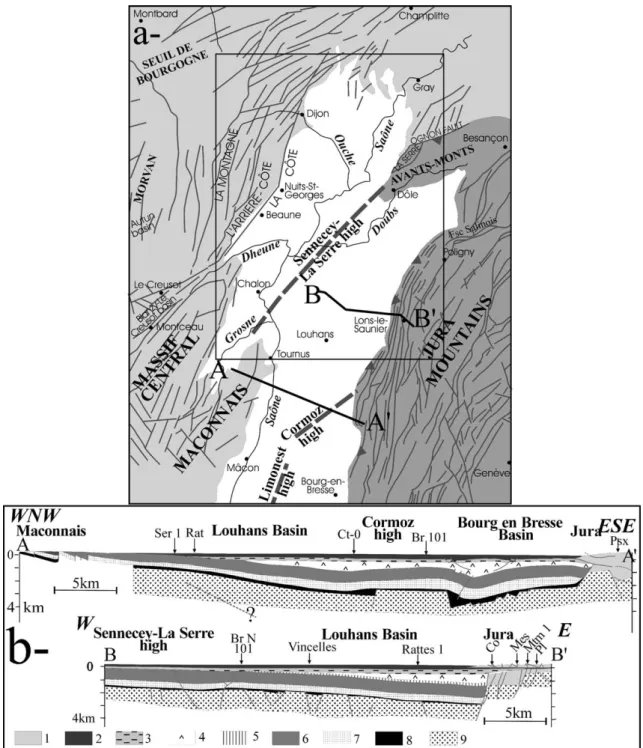
Fig. 1.(a) Regional setting of the study area. Bresse graben is in white, Jura in dark grey, western edge of Bresse graben, Burgundy and Massif Central in pale grey. The frame indicates the study area. (b) Regional cross-sections of the Bresse graben. aa′: built up with Jura-Bresse ECORS seismic profile[11]. bb′: built up with oil industry seismic profiles[4]. See positions in (a). For structures in the Miocene to Pleistocene bedding (this study), see cross-sections inFig. 7. 1, Mesozoic in the Jura; 2, Mio,Pliocene; 3, Oligocene limestone and marl; 4, Upper Eocene-Oligocene salt; 5, Cretaceous; 6, calcareous Middle–Upper Jurassic; 7, Marl Lias; 8, Triassic salt; 9, Basement-Permian–Triassic sandstone.
2. Present-day structure of the graben
2.1. Drainage network analysis
In the flat Bresse region where scarps are scarce, the analysis of drainage network (Figs. 2–4) is a useful tool for structural mapping. It is known that studies of drainage patterns bring significant contribution to structural analyses [14], even where structures are buried[15]. Anticlines and synclines generate a particular network[14]related to the induced water shades, including annular drainage and curvi-linear anomalies on their termination (see examples C and D inFig. 3). Faulting and bedding generate rectilinear drainage anomalies (examples A and B inFig. 3).
In Fig. 2, the drainage network extracted from the IGN 1:25 000 topographic maps of the Bresse graben and edges
was supplemented with temporary water courses and back-water deduced from topography. The most important curvi-linear and recticurvi-linear drainage shapes were extracted from this drainage network and the various water shades were identified (examples inFig. 3). Those which can be attributed either to the dip of the bedding or to human construction (canals, forced rivers, ponds, modification due to quarries) were removed. The others can be considered as anomalies due to faulting (rectilinear ones,Fig. 4b) or folding (curvilin-ear pattern,Fig. 4a). In the graben, the age of the outcropping formations varies from the Pliocene to the Quaternary.
Analyses of curvilinear anomalies, local domes and basins and zones of hydrographical convergence indicate a major direction of corrugation, trending NNE–SSW, parallel to Jura thrusts and fold axes (example C inFig. 3). Few undu-lations with NE–SW trending axes (example D inFig. 3) are
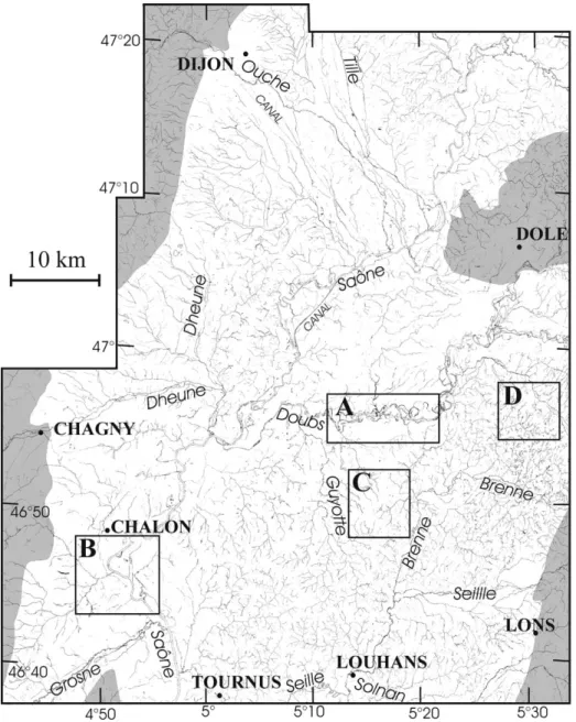
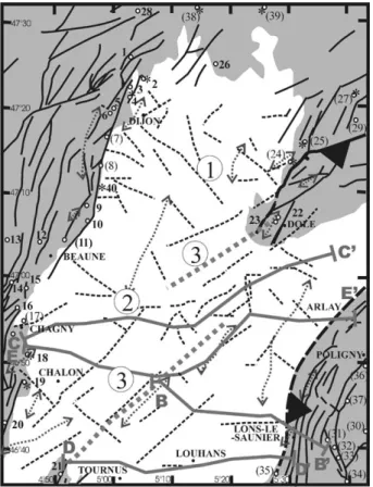
Fig. 2.Drainage network of Northern Bresse extracted from IGN 1:25 000 maps and completed with temporary water courses and backwater deduced from topography. Names of watercourses are in italics, and names of cities in upper case. Bresse edges and Jura as grey background. A, B, C, D: seeFig. 3.
situated near the Jura/Bresse thrust contact and can be inter-preted either as due to yet unrecognised episode of compres-sion trending NE–SW, or more likely to folding associated with strike-slip faulting (along the locally recognised NE–SW trending faults, see D inFig. 3). Some very minor axes trending E–W were suspected near Beaune.
The analysis of rectilinear anomalies, which generally occur along NE–SW, E–W and NE–SW directions (ex-amples A and B inFig. 3, andFig. 4b), allow to suspect three main fault zones in the graben:
(1) A NE–SW (N115–140) trending fault zone from Dijon to Dole, probably forcing the course of the Ouche river (Fig. 2), and then to Poligny, (“1” inFig. 5) is parallel to the major strike-slip faults in Jura (Fig. 1).
(2) A diffuse fault zone nearly trending E–W (N075–100) from Chagny–Beaune to Poligny (“2” in Fig. 5) is situated between the fault set named “faisceau sali-nois” in Jura at the east, and the northern end of the Blanzy-Le Creusot basin in the Massif Central at the west (Fig. 1a). This fault zone is quite parallel to the Ognon thrust fault (Northern Jura,Fig. 1a), and to a transfer fault situated at the north of Dijon (Fig. 1a). (3) A NE–SW (N040–065) trending fault zone from
Cha-lon and Tournus to Dole (“3” inFig. 5) corresponds to the Sennecey-La Serre horst[1,2](Fig. 1a). This fault system crosscuts the NE–SW fault zone. This fault zone shows an apparent horizontal left-lateral offset on
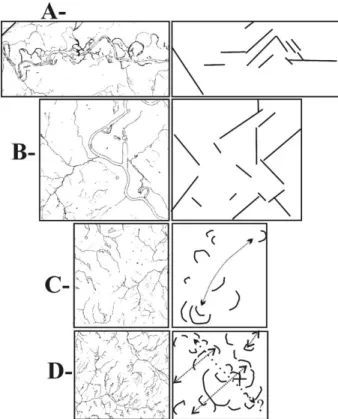
Fig. 3.Method of structural analysis of drainage network. Position of A, B, C and D: seeFig. 2. A, B: examples of relevant rectilinear network anoma-lies, allowing to determine fault traces; C, D: examples of relevant curvili-near network anomalies and variations of dépocentres, allowing to deter-mine fold axes.
Fig. 4.Regional interpretation of structural analysis of the drainage network ofFig. 2, with methodology shown inFig. 3. (a) Curvilinear anomalies, with zones of convergence (3), local domes and basins (4), indicating possible syncline axes (1) and anticline axes (2); 5: approximate position of La Serre high, suggesting an apparent left-lateral offset of nearly 10 km. (b) Rectilinear anomalies, showing preferential orientations trending NE–SW, E–W and NE–SW, with a frequency rose diagram.
both sides of the E–W fault zone (Fig. 5). The southern part of this NE–SW fault zone is parallel to the edge fault near Beaune, and the northern part has the same trend as the Rhin-Saône transfer fault zone.
2.2. Relationships between measured minor faults and suspected major faults
The orientation of multiple sets of joints and faults occur-ring in quarries, roadcuts and natural exposures of the Bresse region was measured in the Jurassic and Oligocene bedding (18 sites,Fig. 5andTable 1). The statistical analysis of joint azimuths (Fig. 6) indicates a preferential N020–030 trend. The faults (Fig. 6) are mainly sub-vertical, and trend N015–
035, N075 and N110. Half of these are normal faults, the other half are strike-slip faults; reverse faulting is poorly represented. The normal faults, trending N020–030 and N075, are in majority sub-vertical, which suggests that they could correspond to reactivated joints or strike-slip faults. The strike-slip faults are sub-vertical and trend mainly N110 for right-lateral faults, and N020 to N070 for left-lateral faults, but other trends are represented, and the apparent incompatibility between the most numerous right-lateral and left-lateral faults (not conjugate faults with angle of 60° between azimuths) suggests a complex polyphase tectonic evolution and/or fault reactivations.
In conclusion, the strike-slip faulting is important and polyphase in this region, and the preferential orientation of measured minor faults (Fig. 6) and trends of major faults suspected by drainage analysis in the graben (Fig. 5) are coherent.
The suspected major fault zones could be corroborated with local preferential orientation of fractures measured at field. Several sites show minor faults with same trends as the regional NE–SW fault zone (“1” inFig. 5) near Dijon (Fig. 5, sites 2 and 4), Gevrey-Chambertin[3]and Dole (site 22). The minor NE–SW fault zone running across Chalon city area (seeFig. 5) is in the continuation of the site of Chagny, where Bergerat[3]measured few faults with the same trend. Some minor fractures trend E–W in the western continuation of the major E–W fault zone (“2” inFig. 5) (sites 15 and 16, and Beaune, see[9]), and in other sites (sites 23 and 10, near an E–W less important fault zone). The NE–SW fault zone (“3” inFig. 5) is probably responsible for normal faulting with this trend at Sennecey-le-Grand (site 21) to the southwest and near Dole to the northeast (sites 22 and 23).
Finally, the trends of the faults detected in the Bresse correspond to typical Variscan fault trends; these presumed faults could thus correspond to reactivated basement faults. The control of the drainage by these faults does not necessar-ily indicate their present-day activity, but at least indicates that they crosscut the Plio-Pleistocene outcropping bedding.
3. Paleostress reconstructions
Paleostress axes were determined from the numerous striae measured on minor faults (nearly 1000 striae on 18 sites, Figs. 5 and 7and Table 1) and from mechanical twinning measured in calcite sampled in the Oligocene con-glomerates of the graben (three samples) and in the Jurassic limestones on the western edge (two samples) (Figs. 5 and 7 andTable 2).
3.1. Inverse methods using fault slip data and of calcite twin data
3.1.1. Fault slip inversion
The inverse analysis of fault slip data allows the determi-nation of paleostress orientations from measurements of the dip direction and sense of slip of numerous minor faults
Fig. 5.Faulting (black dashed lines) and folding (anticline axes in grey dotted arrows) in the Bresse graben (white background) deduced from anomalies of drainage network (Fig. 2), replaced in the regional structural map (on grey background: sub-vertical faults in thin continuous lines, thrusts in thick continuous lines;[3], modified). Encircled numbers 1, 2, 3: see text; grey background indicates western edge of Bresse graben and Jura. cc′, dd′: cross-sections ofFig. 10. The approximate position of La Serre high is indicated by a thick grey dotted line. Dots: studied tectonic sites, stars: sampled calcite. Numbers in bold (Tables 1 and 2): this study, other sites with numbers into brackets (from[3]: 7, 8, 11, 17, 18; from[27,29]: 24, 25, 27, 29, 30, 38, 39; from[34]: 30–37). Site names: 1, Savigny-le-Sec; 2, Pichanges; 3, Asnières-les-Dijon; 4, Toison d’Or; 5, Combe-Valton; 6, Talant; 7, Marsonnay-la-Côte; 8, Gevrey; 9, Nuits-St-Georges; 10, Com-blanchien; 11, Magny; 12, Bouze-les-Beaune; 13, Lusigny-sur-Ouche; 14, St-Romain; 15, Meursault; 16, Chassagne-Montrachet; 17, Chagny; 18, Mercurey; 19, Givry; 20, Buxy; 21, Sennecey-le-Grand; 22, Authume; 23, Mont-Alans; 24, Taxenne; 25, Montagney; 26, Beaumont-sur-Vingeanne; 27, Gy; 28, Is-sur-Tille; 29, Courtemire; 30, Mirebel; 31, Pannessières; 32, Rosnay; 33, Briod; 34, Nogna; 35, Grusse; 36, Poligny; 37, Cht Chalon; 38, Prauthoy; 39, Sacquenay.
Table 1
Stress tensors determined by inverse analysis of fault slips (Angelier’s method)[16,17]. Sites: position onFig. 5; Age, age of studied formation; Bedding, trend and plunge; stress state, regional tectonic event probably associated (c., compression; e., extension); r1, r2, r3, principal axes of the stress tensor (trend-plunge
in degrees); U = (r2– r3)/(r1– r3); M: method (I: INVD; R: R4DT, see text); RUP: estimator of Angelier’s program[17];␣, mean angle between observed
stria-computed shear stress; N, number of data
Site Age bedding Stress state M r1 r2 r3 U ␣ RUP N
1 Kim. <180 01W c. N–S I 168.04 340.86 078.01 0.4 7.9 21 32 e. WNW I 154.80 045.03 315.09 0.5 17.2 41 30 e. NNW I 043.76 275.09 184.11 0.5 10.8 37 9 c. NE I 259.13 003.47 158.40 0.5 5.6 28 24 2 Olig. ? e. WNW I 336.77 206.09 115.10 0.2 13.2 43 6 3 Chattian e. NNW I 287.71 081.17 173.07 0.3 10.0 50 6 040 25S c. NE I 061.39 253.50 155.06 0.7 13.9 39 7 4 Olig. e. WNW I 323.81 132.09 223.02 0.3 13.0 35 14 e. NNW I 344.71 087.04 178.19 0.3 7.3 27 6 5 Combl. e. ENE I 146.64 343.25 250.07 0.2 4.6 26 28 Bath. > I 012.13 128.63 277.23 0.5 36.8 24 55 e. WNW I 334.44 087.41 081.17 0.1 5.5 19 13 c. NE I 037.36 287.24 171.45 0.6 6.1 27 4 c. N–S I 187.13 025.77 278.04 0.4 3.7 27 5 6 Bath. c. N–S I 354.16 116.62 257.23 0.7 15.6 33 36 Call. c. NE I 266.25 057.62 170.12 0.6 3.1 12 10 9 Combl. e. NNW I 103.72 205.04 296.18 0.3 4.9 20 11 Bath. > c. N–S I 356.15 123.66 261.18 0.4 10.5 25 9 e. WNW I 344.72 175.18 084.03 0.2 2.2 11 10 11 Combl. e. NNW I 300.77 051.05 142.12 0.2 17.3 34 26 Bath. > e. WNW I 095.82 220.04 310.06 0.4 10.1 37 53 045 15E c. N–S I 132.02 229.72 041.18 0.2 10.0 39 5 e. NNW I 038.87 231.03 141.01 0.3 10.5 41 78 e. ENE R 106.80 323.08 232.06 0.0 3.2 70 35 12 Oxf–Kim c. N–S I 346.12 119.72 254.13 0.4 8.2 22 29 055 10E e. WNW R 339.63 203.20 106.17 0.1 0.1 27 4 13 Baj. > e. WNW I 021.72 207.17 117.02 0.2 2.3 12 6 14 Oxf. > e. WNW I 356.72 180.18 090.01 0.3 5.7 24 8 15 c. N–S I 309.14 054.45 206.41 0.5 14.5 42 11 e. ENE I 262.66 134.15 039.18 0.2 17.0 42 7 c. NE I 243.03 111.86 333.03 0.8 15.3 34 7 16 c. N–S I 355.08 208.80 085.05 0.4 11.5 39 5 e. WNW R 127.61 025.06 292.28 0.4 5.1 46 10 e. ENE R 201.54 018.36 109.01 0.9 0.8 32 4 20 Baj. < c. N–S I 348.19 227.57 087.26 0.4 11.7 28 8 e. NNW I 279.67 046.14 141.18 0.1 7.8 26 11 21 Bath. < e. ENE I 241.84 357.03 087.06 0.4 3.5 11 8 179 31E e. WNW I 084.81 232.08 323.05 0.4 4.2 14 6 c. NE I 049.16 290.58 147.26 0.1 8.9 26 14
[16–18,20,21]. The method is based on the assumption that the stria on a fault plane is parallel to the resolved shear stress applied on this surface. The fault slip inversion yields a reduced stress tensor (Table 1), including the orientation of the principal stress axes r1, r2, and r3and the value of the U
ratio, which equals (r2– r3) / (r1– r3)[22].
For this study, the INVD and R4DT computerised meth-ods of Angelier[16,17]have been used. The R4DT method corresponds to an iterative calculation of fault tensor-solutions in order to minimise the angle between the ob-served stria on each fault plane and the calculated shear stress [21]. The INVD method uses an analytical inversion to mini-mise both the shear stress and the angle between observed stria and calculated shear stress[17]. The type of fault set to analyse determines the choice of the method[16,17,22].
In case of polyphase faulting, the mechanically consistent fault slips are gathered, taking into account chronological
observations. Such observations deal with superimposed striations on fault surfaces (Fig. 7, Table 1), crosscutting relationships between faults, time relationships between faulting and tilting of the bedding (see text below), etc.
3.1.2. Calcite twin inversion
At low pressure and temperature conditions, calcite aggre-gates deform primarily by twinning along
兵
011¯2其
crystallo-graphic planes named the e-twin planes [23]. Mechanical twinning of calcite crystals occurs on a e plane only if the resolved shear stress acting along this plane equals or ex-ceeds the yield stress value for twinning, ie, 10 MPa[19,24]. For each sampling site (Fig. 5), calcite twin data (twinned and untwined e planes) were collected using the Universal Stage with measurements made on three mutually perpen-dicular thin sections.Table 1 (continued)
Site Age bedding Stress state M r1 r2 r3 U ␣ RUP N
22 c. N–S I 354.08 182.82 085.01 0.5 5.0 18 8 030 02W e. WNW R 004.58 244.17 145.26 0.4 14.7 45 13 c. WNW R 099.09 202.57 003.32 0.1 2.2 61 4 23 Kim. e. ENE R 193.71 331.14 064.12 0.0 5.9 36 5 e. WNW R 125.75 028.02 297.14 0.1 4.0 61 7 26 Kim. < c. N–S I 352.27 193.61 087.08 0.4 8.9 40 12 045 05S e.WNW I 121.82 236.03 327.07 0.4 10.5 31 5 c. NE I 042.10 133.07 257.77 0.4 16.8 46 7
Fig. 6.Statistics on measured faults and joints in all tectonic sites shown inFig. 5. The number of measurements is indicated. (a) Frequency rosace of azimuths; (b) frequency rose diagram of dips.
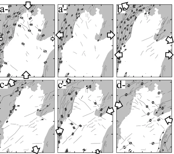
Fig. 7.Local distensional trends (divergent arrows: r3) and compressional trends (convergent arrows: r1) from paleostresses (Table 1) reconstructed by fault slip
inversion (1, 2, 3) and calcite twin inversion (4, 5), replaced in the regional structural map ofFig. 5. 1, 2, 4: this study (1: calculated good quality trends; 2: calculated poor quality trends or approximate trends); 3, 5: see[11,27,29,34]. (a) N–S trending compression, attributed to Pyrenean collision, and (a′) E–W trending Early Oligocene strike-slip distension, attributed to the ending of the Pyrenean compression; (b) WNW trending Oligocene distension; (c) NNW trending distension, attributed to the end of the graben structuring and the very beginning of the Alpine collision, and (c′) ENE compression attributed to the first pulse of the Alpine collision at early Miocene (Helvetic event); (d) WNW compression corresponding to the major episode of Alpine collision at Late Miocene and probably still active nowadays. Values indicate (r1–r3) magnitudes (in MPa) deduced from calcite twinning inversion ([27,29], and this issue). Diagrams:
thin curves represent fault planes, and dots with double arrows (left- or right-lateral) or simple ones (centrifugal-normal; centripetal-reverse) indicate slickenside lineation. Stars indicate stress axes (5 points: r1, 4 points: r2, 3 points: r3). Empty squares represent poles to tension gashes. Full lozenges represent stylolitic
The orientation of paleostress axes from twin data was determined through the Etchecopar’s numerical inversion [19], that has been validated in various regions of unmeta-morphosed and weakly deformed carbonate cover rocks (e.g.,[24–29]). Theoretically, the value of the resolved shear stress must be larger for all the twinned planes consistent with the tensor-solution than for all the untwined planes. Data inversion provides the orientation of principal stress axes and the U ratio[24,25,30–32], but also the maximum differential stress (r1– r3)[24,29].
The inverse process of Etchecopar[19]has been improved to be better adapted to polyphase tectonism [33]. All the measured twinned planes are now used for calculation of each successive stress tensor, and the calcite grain size is taken into account. It results a better identification of the minor states of stress, and a significant decrease of the error margins on the evaluated stress magnitudes.
3.2. Results of paleostress reconstructions
The inversion of fault slip data gives self-consistent re-sults, and results consistent with those obtained in western Bresse[3]and in Jura[34]with the same method, and with those obtained in Burgundy with the same method and with calcite twinning inversion [27](Fig. 7). For each tectonic site, two to five states of stress are generally reconstructed: three compressions trending N–S, ENE and WNW, and three extensions trending WNW, E–W and NNW.
The calcite twinning inversion allowed to reconstruct (Table 2) only some of the states of stress quoted above: in two samples, only the ENE and WNW compressions are reconstructed; in two other ones, the WNW extension is also reconstructed. This indicates that the sampled calcite is more recent than the unreconstructed states of stress. The NNW and E–W extensions are never reconstructed, thus indicating
minor or local states of stress. The WNW compression is reconstructed by calcite twinning in all sampled sites except one, but with low differential magnitudes (Table 2), which traduces that calcite is a more sensible sensitive marker of stresses than faulting[24].
The relative chronology between these events indicates the succession described above. (1) Numerous tension gashes trending N–S (not shown inFig. 7) predate all other structures. (2) The N–S compression (Fig. 7a) is recon-structed in most tectonic sites (numerous NNE–SSW to NE–SW trending left-lateral strike-slip faults and few NE–SW right-lateral strike-slip faults), (3) then the E–W, WNW and NNW extensions are successively reconstructed (Fig. 7a′,b,c). The E–W extension (reactivated joints and NE–SW trending faults) rather trends ENE to E–W and is reconstructed in few sites. The WNW trending extension is reconstructed in quite all sites and samples (conjugate nor-mal faults, reactivated joints and few tension gashes trending NNE to NE–SW). The direction of extension is fan-shaped, from N110 in the South to N140 in the north (Fig. 7b). This phenomenon has also been attributed by Lacombe [29] to stress rotation near the Rhin-Saône transfer fault zone. The NNW extension (reactivated joints and NE–SW and E–W trending faults) is minor and rather corresponds to a radial extension, taking into account the important vertical stress component (U = 0.1–0.3, Table 1). (4) The nearly ENE compression (Fig. 7c′) is reconstructed in few sites and samples (reactivation of NE–SW faults into left-lateral strike-slip faults) along the western edge of the graben. (5) The WNW trending compression (Fig. 7d) is well recon-structed by faulting near Dole (sites 22, 23) and suspected at the south of Chalon (site 21) and was recognised in the north of Dijon[3,27]and in the Jura Mountains[34](reverse and strike-slip faults), but is minor between Dijon and Chalon and detected only with calcite.
Table 2
Stress tensors determined by inverse analysis of calcite twins (Etchecopar’s method)[19]. Site, age, r1, r2, r3, U: seeTable 1; Ech, type of sampled calcite (M,
rock matrix; gash, tension gash with its direction); sa′, intra-program value of the yield stress (see text); MT, NT, respectively total number of twinned and untwined planes considered for tensor calculation; M, N, respectively number of twinned and untwined planes consistent with the result; f, intra-program function indicating quality of the result; Dr, calculated differential stresses
Site Ech Age Type r1 r2 r3 U f MT NT M N Dr
4 M O C ENE 056.29 322.07 220.60 0.1 0.14 33 28 15 27 67 Cd WNW 283.14 137.73 015.19 0.5 0.00 19 27 10 27 35 40 M O C WNW 322.23 055.07 162.66 0.2 0.13 72 38 22 36 35 Ed E–W? 001.17 117.56 262.29 0.7 0.26 52 38 20 34 41 E WNW 252.71 030.14 123.12 0.2 0.03 33 37 13 36 40 2 Gash O C ENE 068.19 164.19 296.63 0.5 0.6 151 62 57 51 42 071 E? 232.56 111.19 011.27 0.2 0.30 93 63 37 57 34 Cd WNW 278.28 036.41 165.36 0.7 0.10 60 63 20 59 31 20 Gash J C ENE 063.27 156.07 260.62 0.4 0.44 66 44 29 40 51 180 C WNW 305.13 211.15 072.70 0.5 0.09 41 42 13 41 34 19 Gash J C NE? 217.16 317.34 106.52 0.7 0.62 173 57 74 50 76 180 E WNW 090.64 223.18 319.18 0.2 0.65 100 56 40 51 36
3.3. Dating of reconstructed tectonic events
The N–S trending compression (Fig. 7a), not observed in the Oligocene conglomerates (conglomerates with salmon pink cement, sites 2, 4, 40), can be interpreted as related to the Eocene Pyrenean collision. Numerous N–S trending ten-sion gashes predate this compresten-sion, and could correspond to syn-lithification Jurassic extension[35]or to a cretaceous tectonic pulse[36,37], or to a strike-slip extensional regime with r1trending N–S and r3trending E–W, preceding the
N–S compression. The first hypothesis could be confirmed with the fact that these tension gashes are observed only in the earliest (Bajocian and Bathonian) rocks, and with the observation of a possible syn-lithification N020 trending normal fault at site 14.
The E–W, WNW and NNW extensions (Fig. 7a′,b,c) are classically gathered into a single E–W to NE–SW extension attributed to the proto-rifting at Oligocene times, responsible for the formation of the graben, with a very beginning during the Middle Eocene[38], main rifting from the Stampian[39] and a probable climax at Chattian[1,8]. The observations of relative chronology forced to separate this phase into three successive states of stress. In the Oligocene conglomerates, only the WNW and NNW extensions were reconstructed (thus occurring during the Oligocene or later). The E–W minor extension thus occurred before the Oligocene, thus could be related to the beginning of the rifting in Bresse at Lutetian to Priabonian times, registered by fluvial-lacustrine deposits[38]. It is also synchronous with the Pyrenean N–S shortening occurring all over the NW-European Platform. These states of stress differ with a permutation of r1and r2
axes. The same state of stress was locally reconstructed in the North-Pyrenean foreland[28]and was dated as Late Eocene– Early Oligocene. The WNW extension is important and probably corresponds to the major extension associated with the formation of the Bresse graben during the Oligocene. The NNW trending minor extension corresponds to a general collapse ending the Oligocene graben structuring (important vertical stress), but this extension is preferentially trending NNW, probably due to the beginning of ENE trending Alpine compression, inducing lateral confinement pressure.
The reconstruction of different extensions rather than one allowed to differentiate two extension possibly correspond-ing to transitional states of stress with the previous Pyrenean compression and with the next Helvetic compression (see below), from one possibly “real extension” that could have fit the difference of motion between Western Eurasia and the remaining part of Eurasia[40].
The ENE compression (Fig. 7c′) could have occurred in continuity with this NNW extension, with a permutation of
r1and r2axes. It is reconstructed in the Oligocene
conglom-erates, and was recognised[41]all over the NW-European Platform and attributed to the “Helvetic” orogenic episode at Early Miocene[3] (Ultra-Helvetic and Pennic Units over-thrusting the “Chaînes Subalpines”[42]). Finally, the WNW compression (Fig. 7d) is classically attributed both to the
“Subalpine” (or “Styrian”) and the “Jurassian” (or “Attican”) tectonic pulses of the Alpine collision [34] (respectively, thrusting of the Chaînes Subalpines over the Molasse basin, and of the Jura over the Bresse [1,43,44]), occurring at Middle–Late Miocene to Pliocene and locally still active nowadays[45].
3.4. Possible structural evolution during the Cenozoic
The Cenozoic structural evolution of the Northern Bresse can be summarised as follows. The Pyrenean tightening trending N–S (Fig. 8a) is well recorded in Bresse, which is a platform at this time. It has induced NNE trending strike-slip left-lateral faulting along the present eastern edge of the graben, and could have activated the NE–SW trending faults with a right-lateral strike-slip motion. The succeeding E–W trending extension is the first episode of rifting even if most likely occurred continuously with the N–S compression (r1–
r2permutation,Fig. 8a′), reactivating the NNE edge faults with a normal to locally left-lateral motion.
The WNW Oligocene major extension (Fig. 8b) has acti-vated the edge faults trending NE–SW trend, and probably activated the NE–SW trending fault zone in the graben with normal motion.
The NNW trending late extension (Fig. 8c) has locally reactivated the NE–SW edge faults, and possibly the NE–SW and E–W fault zones in the graben. At Early Miocene, the succeeding ENE compression (Fig. 8c′) has induced a left-lateral strike-slip motion on the E–W trending faults, and a right-lateral strike-slip motion on the NE–SW trending faults of the western edge and the NE–SW fault zone. The horizon-tal offset of the Sennecey-La Serre horst on both sides on the E–W fault zone is consistent with this state of stress, but the offset (see Fig. 5) is too important for a so minor state of stress. The most probable is that two distinct horsts were initiated (instead of one continuous horst) on fragile pre-existing zones during the Mesozoic, separated by an E–W transfer fault zone.
The repartition of the deformation associated with the ENE and WNW compressions is detailed below.
4. The particular repartition of deformation associated with Mio-Pliocene Alpine compression
4.1. Microstructures associated with Mio-Pliocene Alpine paleostresses
The reconstructed tectonic succession is consistent with the paleostress succession generally recognised in the NW-European Platform [3,28,41,46,47], with N–S Pyrenean compression, Oligocene extensions and E–W to NE–SW Miocene to Quaternary compressions.
However, only very few of the fractures measured were attributed to two tectonic pulses attributed to post-Oligocene Alpine orogenesis (Fig. 7c′,d). The first one, the Helvetic ENE compression is relatively minor[3,28]. It is detected in
the northern and western edges of the graben (Fig. 7c′). Its absence in the eastern edge can be explained by the general obliteration in the Jura Mountains and the Avant-Monts of all previous tectonic events by the second Alpine event, the major Mio-Pliocene WNW compression[34]. However, this second event is minor all along the western edge of the graben, particularly between Dijon and Chalon (Fig. 7d), as is shown by calcite twin inversion.
We tried to determine if this event has structured the graben.
4.2. Post-Miocene deposits in the Bresse graben and structural observations
After the Aquitanian lacustrine sedimentation in the gra-ben, the Upper Miocene–Late Pliocene corresponds to the absence of any deposits in the Bresse graben, most likely related to a general uprising, like the “Seuil de Bourgogne” (Burgundy shelf)[2,8]. This can be attributed to the
propaga-tion of the deformapropaga-tion front after the Helvetic episode. The next Jurassian tectonic episode is already known to be re-sponsible of the deformation of Late Miocene mudstones in the graben[2].
The folds with nearly NNE trending axes detected in the Bresse graben by the analysis of drainage network (Fig. 4a) can also be attributed to this WNW-trending episode of compression.
In numerous sites belonging to the western edge, the bedding (Jurassic and Oligocene in ages) is tilted up to 31° to the SE (Table 1; Fig. 9). Generally, all the reconstructed stress axes and associated faults are tilted with the bedding (Fig. 9). Even the structures associated with the ENE com-pression attributed to the Early Miocene are tilted. As an example (Fig. 9), at Sennecey-le-Grand, the bedding is tilted 31° to the east, the striae associated with a left-lateral motion on E–W faults are not horizontal, and the NE–SW trending tension gashes are not vertical. When the bedding is
back-Fig. 8.Preliminary structural sketch maps (shown on present-day structural map) for each reconstructed tectonic event, deduced from local paleostress reconstructions. Faults shown as continuous lines have motion controlled by outcrop observations, whereas faults shown as dashed line are presumed to be (re) activated. Arrows (strike-slip motion) and rectangles (normal motion) in bold line: motion of these possibly activated faults. a, a′, b, c, c′, d: successive tectonic stages (seeFig. 7).
tilted (as well as the measured fractures) to its original posi-tion (to the horizontal), the striae on E–W faults become horizontal, and the NE–SW trending tension gashes become vertical. This indicates that the major part of the tilting along the margin is more recent than the Early Miocene. The stress axes associated with the WNW compression that were recon-structed by calcite twinning are not tilted because the sampled layers were sub-horizontal.
The agency of Plio-Pleistocene deposits in the graben also indicates that this tectonic activity has continued during their deposition. Petit[48]and Petit et al.[49] have established correlations between various regions of the Bresse graben, based on a climatostratigraphic scale with 9 chronostrati-graphic units, correlated with data established for the rest of the World, using the chronological meaning of the rodents, the malacofauns, the gastropods and the pollens. Two cross-sections in the Plio-Pleistocene deposits of the Bresse graben are shown inFig. 10, and one is retro-deformed inFig. 11. The deposits are organised in two prograding sequences A and B (Figs. 10a and 11), each of them being constituted with fine grain palustral-lacustrine facies at the base, and
sandy-gravel coarse grain facies at the top. Succeeding to the thrust-ing of the Jura, the A sequence (nearly from 5.2 to 2.6 Ma) begins with the Marnes de Beaune and ends with the Caill-outis de Desnes and Sables de Neublans outcropping on the eastern part of the Bresse. The B sequence (from 2.6 to 1.3 Ma) begins with the Marnes de Cessay, Sables de Cormoz and Marnes de Broin, and ends with the Sables d’Agencourt Sands, Marnes de Binges and Sables de Comblanchien.
The spatial repartition of these different units clearly shows (1) a general dipping of bedding to the west (see cc′, Fig. 10b, ee′,Fig. 11), (2) a progressive displacement of the dépocentres to the west, contemporary with the uprising of the oriental edge (see dd′,Fig. 10b, ee′,Fig. 11), and (3) a fault-related drag folding progressing with time at the Jura front (dd′ at Fig. 10b, ee′ at Fig. 11). The tilting of the bedding to the west (demonstrated by the fact that the Saône river does not run in the middle of the basin between Dijon and Mâcon) can be attributed to the progression of a tectonic bulge to the west. The cross-sections also suggest the pres-ence of minor folds and possible thrusts (Figs. 10b and 11), at same positions as those detected with drainage network
Fig. 9.Back-tilting of bedding and measured fractures attributed to the Early Miocene ENE compression for four sites, showing that the tilting is earlier than this compression.
Fig. 10.(a) Age of Plio-Pleistocene chronostratigraphic units; (b) NE–SW and E–W cross-sections[45]showing the agency of Plio-Pleistocene deposits (see positions onFig. 5, respectively cc′and dd′).
analyses (Fig. 4a). The position of the Plio-Pleistocene Bresse basin at the front of the Jura and its sedimentary system thus leads to recognise an overfilled shallow molassic foreland basin[44], at least near the Jura thrust front from the Pliocene to the Early Pleistocene, later most likely amplified by a large wavelength probably lithospheric syncline folding since the Pleistocene (Fig. 11)[50].
Thus, the Mio-Pliocene tectonic event has induced major deformations in the graben. Taking into account these con-clusions, the zone of minor deformation associated to the WNW compression along the western edge needs to be explained.
4.3. Calculating fault reactivation with paleostress magnitudes from calcite twin data
The differential stress values calculated with calcite twin-ning for the WNW compression (this study; [27,29]) are shown inFig. 7d. In the north and the east of the studied area,
the maximum differential stress magnitude averages 42 MPa (sites 5, 19, 20, 24, 25, 27, 38, 39). In the west (along the Bresse edge), the maximum differential stress magnitude averages 34 MPa (sites 2, 4, 20, 40). The sample of site 19 (Fig. 5, Table 2) situated near Chalon has not twinned in response to this state of stress, thus indicating that (r1– r3)
could be less than 20 MPa in this area[24].
All over the studied area, tensors obtained from calcite twinning inversion and from fault slip data inversion gener-ally correspond to strike-slip states of stress (with r2
verti-cal), with r1trending N110, and the mean U ratio is 0.4. We
attempted at quantifying the complete regional Mio-Pliocene Alpine stress tensor in the Bresse graben. We choose to consider that differential stress magnitude equals 42 MPa; this choice will be defended below. The stress magnitudes can be estimated by assuming that the magnitude of the vertical axis (rV) is due to the weight of units situated above.
If the Alpine compression occurred at Late Miocene, after the
Fig. 11.Reconstruction of the structural evolution of the Bresse graben from Pliocene to present-day by putting back beds to flat, using an E–W trending synthetic cross-section[41]from Chagny to Arlay (position E-E′onFig. 5). (1): important uprising; (2): dépocentre (thus subsidence); (3): valley incision (thus uprising). The initial flat surface is due to the Middle–Late Miocene uprising and erosion[38]. (a) Laying of the Cailloutis de Desnes at the back of the Jura trust front (indicating its tectonic activity). (b) Laying of the Sables de Neublans, then the Marnes de Cessay, with progression of dépocentres to the west. The agency (accumulation and folding) of the Marnes de Cessay suggests the activity of a new thrust during their deposition. (c) Laying of the Sables de Cormoz then the Marnes de Broin, with continuing of progression of dépocentres to the west. The thickening of Sables de Cormoz just at the back of the suspected trust could be explained by its tectonic activity. The absence of any deposits at the top of the Sennecey horst suggests its uprising. (d) Sedimentation of the Sables d’Agencourt, with a dépocentre on the western side of the graben, and uprising on the centre and eastern side. The variation of thickness on both sides of the Sennecey horst can be interpreted at a fault offset due to its tectonic activity. (e) Synthetic cross-section from Petit[41]of present-day agency of Plio-Pleistocene deposits, showing the deposition of the Sables de Comblanchien and Marnes de Binge at the eastern part of the Bresse (which could be due to a reactivation of the Jura trust front), valley incisions in all the Basin, then a general subsidence and/or uprising of the both edges.
episode of erosion at Early-Middle Miocene times and before the Quaternary, the value of r2can be calculated by
estimat-ing the weight of the Plio-quaternary units. The thickness of these sediments (h) is quite nil on the edges and at maximum 60 m in the middle of the graben.
Thus, the maximum value of r2is:
r2=rv=qgh=共 2.3×10³ 兲·×10·×60=1.38×10⁶Pa, thus nearly 1.4 MPa
The value of r2can thus be neglected; the mean values of
r1and r3can easily be calculated at 0–60 m:
r3= −U共 r1−r3兲= −16.8MPa
r1=r3共 1−1⁄U兲=25.2MPa
This calculated mean Mio-Pliocene Alpine state of stress is probably a good evaluation in the north and the west of our region of interest; it must be considered as a probable rough approximation of the real one in the graben, in default of any other information. The calculated values of r1 and r3 are
overestimated for the SW of the study zone, because calcite has not recorded any stress (Fig. 7d).
The applied stress on a fault plane P, with an angle named
h between r3and P, and a dip d, is decomposed into a shear
stress s and a normal stress rN:
rN=共 r1·cos2h+r3·sin2h兲·sin2ds=共 r1−r3兲·sinh·cosh·sind
Our calculations allow evaluating rNand s values for each
fault at less than 60 m in response to the WNW Alpine compression (Fig. 11). The points situated above the Byer-lee’s friction curve (s = 0.85rN) [13] indicate faults that
could have been reactivated.
Calculations were not realised for important depth, be-cause no data allowed to calculate the values of differential stress. If these values are nearly independent with depth, the calculated value of r2increases at increasing depth, thus the
Mohr diagram moves to the right, indicating that faults that can be reactivated are less and less numerous.
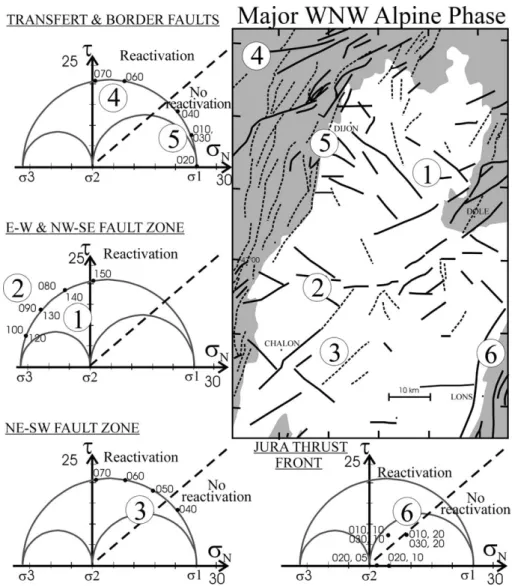
Fig. 12.Position of faults on Mohr diagrams in response to a nearly N110 trending compression, with U = 0.4, no vertical stress and (r1– r3) = 42 MPa. On
Mohr diagrams: friction curve in dashed line, initiation curve (approximate position) in dotted line. The fault azimuth is indicated beside each point on the curve, and is followed by the dip when not vertical. On the structural map: possibly activated faults in thick lines, other ones in dashed lines.
The faults situated at the north of Dijon, sub-vertical and trending N060–070, parallel to the Rhine-Saône transfer fault zone (“4” inFig. 12), can be easily reactivated (see sites 38 and 39)[27], but the edge faults of the western edge of the graben, sub-vertical and trending N010–040 (e.g., La Mon-tagne, La Côte and L’Arrière-Côte faults, Fig. 1; “5” in Fig. 12) cannot be reactivated.
For the NE–SW trending faults (“3” inFig. 12), the N060– 070 vertical faults can be easily reactivated; those trending N050 could be reactivated, but not the most numerous ones, trending N040–045. For the NE–SW trending faults (“1” in Fig. 12), the N120–150 vertical faults can be easily reacti-vated (into left-lateral normal faults), those trending N120– 140 can even be initiated. The N075–100 vertical faults (“2” inFig. 12) can be easily reactivated (into right-lateral normal faults), and even be initiated.
On the eastern edge (Jura and La Serre, “6” inFig. 12), with our calculations, the N010 and N030 trending faults can be reactivated only if the dip is less than 20°, and those trending N020 cannot be reactivated.
4.4. A possible sketch of the Bresse evolution during Mio-Pliocene compression
Along the western edge, most tectonic features corre-spond to basement sub-vertical NNE trending faults that cannot be reactivated. This could partially explain the ab-sence of any structure associated to the WNW compression. However, this cannot explain why stress magnitudes are less important than elsewhere (except eventually a local perturba-tion of the stress field induced by the blocking of these major structures). A compression trending WNW is recorded in western France far from this region (e.g., in the north of the Massif Central[41], and in England[46]). If this compres-sion is also due to the Mio-Pliocene Alpine collicompres-sion, the low stress values along the Bresse western edge correspond to a local phenomenon. The tilting of the western edge can be due to folding. It is known that the magnitude of the compres-sional stress slightly decreases on the top of an anticline, sometimes reaching a perpendicular extension usually called “extrados”[26]. The bulge of the Seuil de Bourgogne[2]at the Late Miocene and the tilting of the Bresse could both correspond to a same uprising in this area (Fig. 13). As shown by Lefort and Agarwal[50], the crust buckling has induced a subsidence (synform) on the location of the Bresse graben, and the uplift of the Seuil de Bourgogne.
The NE–SW fault zone is characterised by the presence of sub-parallel folds, and the Jura is carried forward at its northern part (Ognon faults). The minor folds trending par-allel to the Jura thrust front, that were detected in the graben, are nor continuous on both sides on the fault zone. All these phenomena let to recognise a transfer fault zone (Fig. 13), comparable to the one that was detected more to the north [51].
5. Conclusions
Our analysis of the drainage network allowed proposing a structural map of the Northern Bresse graben. The NE–SW trending Sennecey-La Serre horst is segmented. Another NE–SW trending fault zone runs from Dijon and Dole to Poligny. These faults are most likely rooted in the basement and inherited from the Variscan. Some smooth folds with NNE trending axes were also detected in the Plio-Pleistocene levels.
We reconstructed the Cenozoic tectonic evolution by the analysis of minor fault slips. The structural evolution can be roughly deduced from our tectonic study. During the Pyre-nean collision, the Bresse was a continental platform. The N–S trending compression has activated the NNE trending faults of the present western edge of the Bresse graben. The collapse along these faults during the WNW trending exten-sion at Oligocene times is responsible for the present graben shape. The Alpine collision has induced a WNW compres-sion from the Late Miocene to the Pleistocene, responsible for a progression of deformation to the west, stigmatised by tilting to the west and smooth folding of the Plio-Pleistocene deposits in the graben, thus behaving as a shallow molasse basin. This compression is minor on the western edge be-tween Dijon and Chalon; it could be due to the uprising of the western edge, at the same time as the Seuil de Bourgogne.
Fig. 13.Structural schematic map of the studied area (same asFig. 5) gathering the structural and tectonic information associated with the Mio-Pliocene Alpine compression and induced stress repartition. Data: paleos-tress reconstructions of the WNW compressional stage (from Fig. 7d). Activated faults (thick full lines) and blocked faults (thin dashed lines): see
Fig. 12. Arrows: strike-slip motion; triangles: thrusting. Jura and Bresse edges in grey.
Acknowledgements
This study was supported by the “Centre des Sciences de la Terre, Université de Bourgogne (Dijon, France)”, and the “Institut de Radio-protection et de Sûreté Nucléaire” (IRSN, Fontenay-aux-Roses, France, post-doctoral grant to M. Rocher).
References
[1] P. Rat, Les phases tectoniques au Tertiaire dans le Nord du fossé bressan et ses marges bourguignonnes en regard des systèmes d’érosion et de sédimentation, C. R. Somm. Soc. Géol. Fr. 5 (1978) 213–214.
[2] P. Rat, Une approche de l’environnement structural et morphologique du Pliocène et du Quaternaire bressans, Géol. Fr. 3 (185) (1984) 185–196.
[3] F. Bergerat, Apports et résultats de l’analyse microstructurale dans l’étude de la Bresse chalonnaise (fossé de la Saône): tectonique cassante et paléo-champs de contrainte au Tertiaire, Bull. Inf. Géol. Bass, Paris 23 (2) (1986) 17–22.
[4] G. Blanc, B. Doligez, D. Lajat, A. Mascle, Evaluation du potentiel pétrolier de la Bresse et de sa bordure jurassienne, France, Bull. Soc. Géol. Fr. 162 (2) (1991) 409–432.
[5] G. Lienhardt, Géologie du bassin houllier stéphanien et de ses morts terrains, Mém. BRGM Orléans 9 (1962).
[6] P. Chauve, J. Martin, E. Petitjean, F. Sequeiros, Le chevauchement du Jura sur la Bresse. Données nouvelles et réinterprétation des sond-ages, Bull. Soc. Géol. France IV (5) (1988) 861–870.
[7] P. Rat, G. Cattaneo, G. Doret, Décrochements dans le seuil de Bour-gogne, C. R. Somm. Soc. Géol. Fr. 5 (1975) 231–234.
[8] P. Rat, Structures et phases de structuration dans les plateaux bourgui-gnons et le Nord-Ouest du fossé bressan (France), Geol. Rundsch. 65 (1976) 101–126.
[9] J.-P. Gélard, Rejeu en coulissement sénestre des accidents varisques prolongeant vers la Bresse le fossé de Blanzy-Montceau-les-Mines, C. R. Somm. Soc. Géol. Fr. 1 (1977) 32–34.
[10] J.-P. Gélard, Coulissements horizontaux dans les calcaires jurassiques de Talant (près de Dijon) et preuves microtectoniques du caractèe polyphasé de la fracturation en Bourgogne, Bull. Sc. Bourg. 32 (2) (1979) 59–69.
[11] F. Bergerat, J.L. Mugnier, S. Guellec, C. Truffert, M. Cazes, B. Damotte, F. Roure, Extensional tectonics and subsidence of the Bresse basin: an interpretation from ECORS data, in: F. Roure, P. Heitzmann, R. Polino (Eds.), Deep Structure of the Alps, Mém. Soc. Géol. Fr., N. S., 156, 1990.
[12] F. Chevalier, Analyse structurale et microtectonique des deformations tertiaires de la plate-forme bourguignone, Centre des Sc. de la Terre, Univ. de Bourgogne, France, 1997 Secteurs de Dijon et Beaune, unpub. D. S. E. R 63 p.
[13] J.D. Byerlee, Friction of rocks, Pure Appl. Geophys. 116 (1978) 615–626.
[14] B. Deffontaines, Développement d’une méthodologie d’analyse mor-phostructurale et morphotectonique, Analyse des surfaces envel-oppes, du réseau hydrographique, et modèles numériques de terrain. Applications au NE de la France, Ph.D. Thesis, Univ. P. & M. Curie, 1990 Rapport Interne BRGM 32005.
[15] J.Y. Scanvic, Utilisation de la télédétection dans les Sciences de la Terre, Manuels et méthodes, Bureau de Recherche Géologique et Minière 7 (1983).
[16] J. Angelier, Tectonic analysis of fault slip data sets, J. Geophys. Res. 89 (B7) (1984) 5835–5848.
[17] J. Angelier, Inversion of field data in fault tectonics to obtain the regional stress. III: a new rapid direct inversion method by analytical means, Geophys. J. Int. 103 (1990) 363–376.
[18] E. Carey, B. Brunier, Analyse théorique et numérique d’un modèle mécanique élémentaire appliqué à l’étude d’une population de failles, C. R. Acad. Sc. (D) 279 (1974) 891–894.
[19] A. Etchecopar, Etude des états de contraintes en tectonique cassante et simulation de déformations plastiques (approche mathématique), Ph. D. Thesis, Univ. Sciences & Techniques du Languedoc, Montpellier, 1984 270 pp.
[20] A. Etchecopar, G. Vasseur, M. Daignieres, An inverse problem in microtectonics for the determination of stress tensor from fault stria-tion analysis, J. Struct. Geol. 3 (1981) 5–65.
[21] M. Guiraud, O. Laborde, H. Philip, Characterization of various types of deformation and their corresponding deviatoric stress tensors using microfault analysis, Tectonophysics 170 (3/4) (1989) 289–316. [22] J. Angelier, Sur l’analyse de mesures recueillies dans des sites faillés:
l’utilité d’une confrontation entre les méthodes dynamiques et ciné-matiques, Comptes-Rendus de l’Académie des Sciences (D) 281 (1975) 1805–1808 (erratum; ibid., 1976, 283, 466).
[23] F.J. Turner, D.T. Griggs, H. Heard, Experimental deformation of calcite crystals, Geol. Soc. Am. Bull. 65 (1954) 883–934.
[24] C. Tourneret, P. Laurent, Paleostress orientations from calcite twins in the north Pyrenean foreland, determined by the Etchecopar inverse method, Tectonophysics 180 (1990) 287–302.
[25] O. Lacombe, J. Angelier, P. Laurent, Determining paleostress orienta-tions from faults and calcite twins: a case study near the Sainte-Victoire range, Tectonophysics 201 (1992) 141–156.
[26] M. Rocher, O. Lacombe, J. Angelier, R.W. Chen, Mechanical twin sets in calcite as markers of recent collisional events in a fold-and-thrust belt: evidence from the reefal limestones of southwestern Tai-wan, Tectonics 15 (5) (1996) 984–996.
[27] O. Lacombe, J. Angelier, F. Bergerat, P. Laurent, C. Tourneret, Joint analyse of calcite twins and fault slips as a key for deciphering polyphase tectonics: Burgundy as a case study, Tectonophysics 182 (1990) 279–300.
[28] M. Rocher, O. Lacombe, J. Angelier, B. Deffontaines, F. Verdier, Cenozoic faulting and folding in the North Pyrenean foreland (Aquitaine Basin, France): insights from paleostress reconstructions, J. Struct. Geol. 22 (2000) 627–645.
[29] O. Lacombe, Maclage, fracturation et paléocontraintes intraplaques : application à la plateforme carbonatée ouest-européenne, Ph.D. The-sis, VI, Université de Paris, 1992 316 pp.
[30] F.J. Turner, Nature and dynamic interpretation of deformation lamel-lae in calcite of three marbles, Am. J. Sci. 251 (1953) 276–298. [31] D. Dietrich, H. Song, Calcite fabrics in a natural shear environment,
the Helvetic nappes of western Switzerland, J. Struct. Geol. 6 (1984) 19–32.
[32] M. Burkhard, Determination of paleostress axes orientations from fault, twin and earthquake data, Ann. Tectonicae 1 (1987) 48–57. [33] M. Rocher, S. Baize, M. Cushing, Y. Lozac’h, F. Lemeille, Stresses
induced by the Alpine collision since the Miocene in the NW Euro-pean Plate, EUG/EGS/AGU, Nice, France (6–11 avril 2003). [34] C. Homberg, Analyse des déformations cassantes dans le Jura et
modélisation numérique des perturbations des contraintes autour d’accidents majeurs, Ph.D. Thesis, Univ. P. & M. Curie, Paris, France, 1997 306 pp.
[35] D. Quesne, M. Guiraud, J.-P. Garcia, J. Thierry, B. Lathuilière, N. Audebert, Marqueurs d’une structuration extensive jurassique en arrière de la marge nord-téthysienne (monts du Mâconnais, Bour-gogne, France), C. R. Acad. Sc. Sc. de la Terre et des Pl. 330 (2000) 623–629.
[36] P. Rat, Sur le comportement du futur Seuil de Bourgogne au Crétacé, Bull. Soc. Géol. Fr. 7 (X) (1969) 393–402.
[37] R. Curnelle, P. Dubois, Evolution mésozoïque des grands bassins sédimentaires français (bassins de Paris, d’Aquitaine et du sud-est), Bull. Soc. Géol. Fr. 8 (II) (1986) 529–546.
[38] W. Sissingh, Comparative tertiary stratigraphy of the Rhine graben, Bresse graben and Molasse basin: correlation of Alpine foreland events, Tectonophysics 300 (1–4) (1998) 249–284.
[39] A. Lefavrais-Raymond, Contribution à l’étude géologique de la Bresse d’après les sondages profonds, Mém. BRGM, Orléans 16 (1962) 170.
[40] X. Le Pichon, F. Bergerat, M.-J. Roulet, Plate kinematics and tecton-ics leading to the Alpine belt formation; a new analysis, Geol. Soc. Am. Spec. Paper 218 (1988) 111–131.
[41] F. Bergerat, Stress fields in the European platform at the time of Africa–Eurasia collision, Tectonics 6 (1987) 99–132.
[42] S. Guellec, J.L. Mugnier, M. Tardy, F. Roure, Neogene evolution of western Alpine foreland in the light of ECORS data and balanced cross-sections, Mém. Soc. Géol. Fr. 156 (1990) 165–184.
[43] J. Ricour, Le chevauchement de la bordure occidentale du Jura sur la Bresse dans la région de Lons-le-Saunier; indices d’hydrocarbures dans le Trias, Bulletin der Vereinigung Sschweizerisches Petroleum 23 (64) (1956) 57–70.
[44] O.A. Pfiffner, Evolution of the north Alpine foreland basin in the Central Alps, Int. Assoc. Sedimentol. Spec. Publ. 8 (1986) 219–228. [45] A. Becker, The Jura Mountains—an active foreland fold-and-thrust
belt? Tectonophysics 321 (2000) 381–406.
[46] C. Hibsch, J.J. Jarrige, E.M. Cushing, J. Mercier, Palaeostress analy-sis, a contribution to the understanding of basin tectonics and geody-namic evolution, example of the Permian/Cenozoic tectonics of Great Britain and geodynamic implications in western Europe, Tectono-physics 252 (1995) 103–136.
[47] T. Villemin, Tectonique en extension, fracturation et subsidence: le fossé rhénan et le bassin de Sarre-Nahe, Thèse de Doctorat-ès-sciences, Université P. et M. Curie, Paris, 1986 258 pp.
[48] C. Petit, Un bassin d’avant-pays pelliculaire. La bresse au Plio-Pléistocène, Ph.D. Thesis, Univ. de Bourgogne, Dijon, France, 1993 355 pp.
[49] C. Petit, M. Campy, J. Chaline, J. Bonvalot, Major paleohydrographic changes in Alpine foreland during the Plio-Pleistocene, Boreas 25 (1996) 131–143.
[50] J.P. Lefort, B.N.P. Agarwal, Topography of the Moho undulations in France from gravity data: their age and origin, Tectonophysics 350 (3) (2002) 193–213.
[51] B. Nivière, T. Winter, Pleistocene northwards fold propagation of the Jura within the southern upper Rhine graben: seismotectonic implica-tions, Global Planet, Change 27 (1–4) (2000) 263–288.
![graphic planes named the e-twin planes [23]. Mechanical twinning of calcite crystals occurs on a e plane only if the resolved shear stress acting along this plane equals or ex-ceeds the yield stress value for twinning, ie, 10 MPa [19,24].](https://thumb-eu.123doks.com/thumbv2/123doknet/13426249.408380/8.892.61.823.172.359/graphic-planes-mechanical-twinning-calcite-crystals-resolved-twinning.webp)


![Fig. 11 . Reconstruction of the structural evolution of the Bresse graben from Pliocene to present-day by putting back beds to flat, using an E–W trending synthetic cross-section [41] from Chagny to Arlay (position E-E ′ on Fig](https://thumb-eu.123doks.com/thumbv2/123doknet/13426249.408380/14.892.107.776.115.630/reconstruction-structural-evolution-bresse-pliocene-trending-synthetic-position.webp)