A Distributed Architecture for Mobile,
Location-Dependent Applications
by
Anit Chakraborty
S.B., Computer Science and Engineering Massachusetts Institute of Technology (1999)
Submitted to the Department of Electrical Engineering and Computer Science
in Partial Fulfillment of the Requirements for the Degree of
Master of Engineering in Electrical Engineering and Computer Science
at the
MASSACHUSETTS INSTITUTE OF TECHNOLOGY
May 2000
( Copyright 2000 Anit Chakraborty. All rights reserved.
The author hereby grants to M.I.T. permission to reproduce and distribute publicly paper and electronic copies of this thesis document.
Author ... .... Department of Electrical Engineering and Computer Science
May 16, 2000 C ertified by ... ... ... Hari Balakrishnan Assistant Professor Thesis Supervisor Accepted by... ... Arthur C. Smith
Chairman, Department Committee on Graduate Theses
C
MASSACHUSETTS INSTITUTE
OF TECHNOLOGY
A Distributed Architecture for Mobile, Location-Dependent
Applications
by
Anit Chakraborty
Submitted to the
Department of Electrical Engineering and Computer Science May 16, 2000
In Partial Fulfillment of the Requirements for the Degree of Master of Engineering in Electrical Engineering and Computer Science
Abstract
As pervasive computing becomes a reality, users will be able to interact with comput-ing services which will all work together in a seamlessly integrated system. Resource discovery is a key feature of pervasive computing which allows users simple and con-venient access to resources. While there are several resource discovery systems in ex-istence which are essential to pervasive computing, the support for location-based re-source discovery is uncommon. The goal of this work is to integrate a location-support system with a resource discovery system to support location-based resource discov-ery. Our integrated system provides an in-building solution which is cost-effective, scaleable, and distributed. In order to protect the user's privacy, the system provides location discovery services without receiving any information from the user. We have also implemented a simple scripting language which thin clients can use to control and interact with network services. To demonstrate the power and functionality of this system, we have deployed several location-dependent applications including a map-based service discovery application with little manual configuration.
Thesis Supervisor: Hari Balakrishnan Title: Assistant Professor
Acknowledgments
This thesis was the product of many people who helped shape it and provided feed-back, direction, and encouragement. I would especially like to acknowledge the fol-lowing people:
Professor Hari Balakrishnan who allowed me to pursue a project which greatly interested me. He gave me the opportunity at every step in defining the direction of my research so I would fully enjoy it.. Given all the circumstances surrounding my research and the resulting thesis, I am indebted to him for providing me the motivation to continue pressing forward with my work and finish it.
Elliot Schwartz and my officemate William Adjie-Winoto for designing and im-plementing the first version of the Intentional Naming System which was an integral part of my research.
Bodhi Priyantha for breathing life into my non-functioning hardware when nothing was working. And I must thank him for accompanying me in the lab during the late nights. We learned much from each other while chatting over many cold glasses of
Coca-Cola.
Jeremy Lilley for figuring out many of my most difficult bugs and of course for starting the 504 Twix tradition. Allen Miu for all the great conversations we had which always took my mind off of my research for some rest and relaxation.
John Ankcorn and Matthew Welborn for allowing me to climb on their desks in the middle of the day to put up my radio transmitters.
My roommates Okan Alper, Hitesh Mehta and especially my friend, Sudipta
Sen-gupta, for providing support and insight while I was writing my thesis.
Finally, I must thank my mother and father. When things looked the worst, they believed in me and made sure that I kept on looking forward.
Contents
1 Introduction
1.1 Related Work . . . .
1.1.1 Olivetti's Active Badge System . . . . 1.1.2 AT&T Bats . . . .
1.1.3 Microsoft Research's RADAR . . . . 1.2 Background: Intentional Naming System (INS) . . . 1.3 Design Goals . . . . 1.4 Contributions of this Thesis . . . . 1.4.1 INRClientLib . . . . 1.4.2 RF-Based Distributed Location Support System 1.4.3 Lightweight Scripting Model . . . . 1.4.4 Applications . . . .
1.5 O utline . . . .
2 Intentional Naming System (INS) 2.1 Expressive Naming . . . . 2.2 Responsiveness . . . . 2.3 Robustness . . . . 2.4 Easy Configuration . . . .
3 INRClientLib:The INS Client 3.1 Design Goals . . . . 3.2 Operational Overview . . . 3.3 Architecture . . . . 3.4 Implementation . . . . API with
U
ser 7 8 9 . . . 10 . . . 11 . . . 12 . . . 13 . . . 14 . . . 14 Anonymity . . . 15 . . . 15 . . . 15 16 16 18 19 19 20 20 21 22 24 26 . . . . 2 6 . . . . 2 7 . . . . 2 8 . . . . 2 9 . . . . 3 0 . . . . 3 0 . . . . 3 1 . . . . 3 2 4 Location-Support System 4.1 Design Goals . . . . 4.2 Architecture . . . . 4.2.1 Beacon-Receiver Protocol 4.2.2 Receiver Algorithms . . . 4.3 Implementation . . . . 4.3.1 Packet Format . . . . 4.3.2 Hardware . . . . 4.3.3 Software . . . . 144.4 INS Integration . . . . 36
4.5 Evaluation . . . . 37
4.5.1 Methodology . . . . 37
4.5.2 Results and Analysis . . . . 38
4.5.3 A New Approach . . . . 39
5 Lightweight Downloadable Code 41 5.1 Design Goals . . . . 41
5.2 LAS Lifecycle . . . . 42
5.3 Language Specification . . . . 42
5.4 Implementation . . . . 44
6 Applications 45 6.1 Service Discovery Application . . . . 45
6.2 MP3 Server . . . . 47
6.3 TV Server . . . . 48
7 Conclusion 49 A Lightweight Applet Scripting Specification 50 A.1 Control Overview . . . . 50
A.2 Object Requirements . . . . 51
A.3 Script Specification . . . . 51
A.4 Event Specification . . . . 53
A.4.1 Events . . . . 53
A.4.2 Alerts . . . . 54
A.4.3 Exiting . . . . 54
List of Figures
1-1 BAT Operational Overview . . . . 11
2-1 A graphical view of an example name-specifier . . . . 17
2-2 A wire representation of the name-specifier shown in Figure 2-1. . . . 17
2-3 INS A rchitecture . . . . 18
3-1 INRClientLib Architecture . . . . 22
4-1 Location Packet Format . . . . 30
4-2 Control Packet Format . . . . 31
4-3 Schematic for Location Beacon/Receiver . . . . 32
4-4 Receiver Server Architecture . . . . 34
4-5 Location Manager Error Rates . . . . 38
4-6 Radiation Patterns of a Straight Antenna [20] . . . . 39
5-1 The Lifecycle of a LAS Application . . . . 42
5-2 A sample LAS script . . . . 43
5-3 A LAS TV Remote Control . . . . 44
6-1 Screen Shot of Service Discovery App . . . . 46
Chapter 1
Introduction
In the near future, numerous mobile and wireless devices will join the traditional desktop computer on the network as more and more users demand the ability to com-pute and gain access to information while mobile. While considerable progress has been made in recent years to enable network-layer connectivity for mobile hosts [13],
higher-layer functionality such as discovering and interacting with a particular com-puting resource or service based on location has not yet received as much attention. Attempting to locate and find services in an indoor environment such as an office building is still a difficult task. Most environments do not yet have a resource discov-ery system through which a user might easily find simple and common services such as a printer. However, a resource discovery system by itself is not sufficient to solve this problem. The user must have some notion of his location so he can find a nearby printer and not just any random printer. The problem cannot be solved without a location support system used in conjunction with a resource discovery system.
For example, consider the following scenario. A person uses a laptop to avoid using two different computers at home and at work. At both locations the user has several office components on the local area network such as a printer, scanner, fax machine, etc. In addition, there are a few extra components present at home that are not available at work such as a stereo or TV. Today, when the user goes from the office to his home and vice versa, the user must reconfigure all of his laptop's networking settings. Secondly, there may be several drivers or pieces of software that
are available at home and not at work such as the stereo remote control. Ideally as the user travels, the list of services available to the user will depend on availability at the user's location. While device drivers for a printer may need to be installed to work properly, it may not be necessary to install software for every device on the network. Many devices such as the stereo in this example have very simple controls that should be represented via downloadable code or an applet rather than a complex application. This scenario describes an environment where the network and services on the network are ubiquitous [23] or pervasive [5, 18] from the user's perspective. There is currently no existing framework that ties together location based resource discovery as described in this scenario.
1.1
Related Work
There has been considerable amount of work done in both areas of location tracking and resource discovery but not much on incorporating the two under one umbrella. In the area of resource discovery, there are a number of existing systems. Sun has created Jini [12]. Jini creates a "federation of networked devices" using JAVA's RMI for communication. It has what it calls a "lookup service" which represents a col-lection of services. However, Jini does not handle resource discovery in a dynamic environment such as our target environment. It is a centralized approach to resource discovery and requires IP Multicast for bootstraping. The Service Location Pro-tocol (SLP) [16] uses centralized directory agents for discovery of network services. However, centralized architectures are prone to single-point-of-failure problems. The Berkeley Service Discovery Service (SDS) [4] works in a similar way but adds authen-ticated communication and a hierarchal structure for wide-area application.
There are a number of systems available today that aid in location tracking. One common solution used today is known as RFID [2]. RFIDs are small tags that can contain both active and passive electromagnetic elements. The basic idea behind these tags is selective reflection of electromagnetic radiation. A tracking device will directs electromagnetic radiation at these tags, and the tags will selectively reflect
back a portion of the spectrum. The reflected spectrum represents the ID of the tag. These are often used in the cattle industry to track cattle, and also at automobile toll-booths for no-stop electronic toll collection. These devices are often severely affected by the environment, for example large metal objects can affect the electromagnetic
transmissions.
A commonly-used wide area technology is the Global Positioning System (GPS) [6].
GPS uses signals from a number of satellites in geosynchronous orbit. By receiving
signals from three or more satellites a device located on the earth's surface can tri-angulate its position. However, this technology does not work very well in an indoor environment where the signals not always penetrate the walls.
Other than these two methods of location tracking, there are three projects de-signed specifically for purposes of location tracking in mobile computing environ-ments. One of the first location tracking systems was the Active Badge system from Olivetti Labs [22]. A follow-on system was created recently at AT&T Labs (previ-ously Olivetti) called the Bat System [9, 8]. A third system came out of Microsoft
Research and is called RADAR [3]. We survey these below.
1.1.1
Olivetti's Active Badge System
The Active Badge system tracks objects and puts this information into a central database. Each object that is to be tracked is given an "active badge" which has a unique ID. This ID is transmitted using infrared into its environment where there are infrared sensors throughout the building that pick up the transmission. The sensors send this information to a central database that keeps track of where the user is. In this system, the walls act as a boundary between physical locations since infrared cannot travel through walls.
One of the primary concerns with using the Active Badge system is the user's right to privacy. If the user asks the system to track his location, the system knows where the user is at all times. The only way to avoid this is to turn off the badge. But then the user is not being tracked at all, and the user can then no longer utilize location based services. Another drawback of this system is that it suffers from
line-of-sight issues. Because infrared generally cannot go through solid objects, tracking is somewhat error prone. For example when a person is located between the transmitter and the sensor, there is a high probability the sensor will not pick up the transmission.
1.1.2
AT&T Bats
Like the Active Badge system, the Bat system also tracks objects and puts this location information into a central database. However, some of the problems with the Active Badge system are solved by the Bat System. Instead of using infrared, the Bat system uses both ultrasound and RF to track its users.
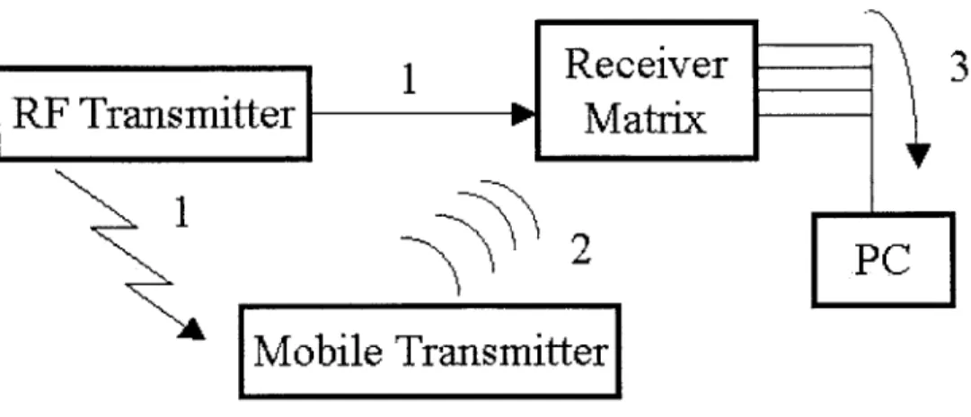
There are three components in this system - an RF base station, a receiver ele-ment, and a transmitter. The RF base station sends out an RF message addressed to each transmitter one by one. The transmitter has an RF transceiver which listens for RF messages from the RF base station. When the RF transceiver receives a message addressed to it, it causes the ultrasonic transmitters located on the same transmitter to emit an ultrasonic pulse. Receiver elements located throughout the environment (typically on the ceiling) associate the ultrasonic pulses from the transmitter with the initial RF transmission from the RF base station. The time (which translates into distance) between these two transmissions is recorded and sent to a central database for processing. By collecting enough readings, calculations on this data yield loca-tion readings accurate to a few centimeters. An operaloca-tional overview of how these components work together is further described in Figure 1-1.
Like in the Active Badge system, user-privacy issues arise in this system as well.. In addition, the entire system is heavily dependent on the central database. Once the processing power of the central database saturates and as more objects to be tracked are added to the system, tracking inevitably slows down. A major advantage of the Bat system over the Active Badge system is its use of RF and ultrasound rather than infrared. By using RF, the system no longer suffers from dead-spots that tend to appear when using the infrared spectrum.
1
3
2
Mobile Transmitter]
Figure 1-1: 1. The RF base station transmits a unique ID via RF to all the mobile transmitters. At the same time, it sends a reset signal to the receiver elements in the receiver matrix. 2. The mobile transmitter with the same ID that is broadcasted in step 1 trasmits an ultrasonic pulse from each of its ultrasound transmitters. 3. The ultrasound receivers located on the receiver elements record the time between the reset signal from the RF base station and the received ultrasound signal from the mobile transmitter. This data is fed to a central computer which processes the information to determine where the mobile transmitter is located.
1.1.3
Microsoft Research's RADAR
The RADAR system provides location-support information from lookup tables cre-ated from an existing RF network (in this case a wireless LAN). During an off-line phase, a network of RF transmitters is set up and measurements are taken at various points throughout the building. A measurement consists of the RF signal strength from each transmitter to the receiver at that point. So, the final result is a database of RF signal strengths from each transmitter at various positions in the building.
After this is complete, the system is ready for normal operation. The mobile receiver samples the signal strength from each transmitter and sends this information to a central computer. The central computer then obtains a best fit for this data against the positions from the database built during the off-line phase and produces a location. If all of this information is colocated with the receiver, the receiver can also compute the location based on received information, rather than having to send the data to a central computer.
In receiver/central computer setup, the user's privacy is not protected since the central computer is required to do processing on behalf of the user. However, in the receiver only setup, the receiver's privacy is protected. However, by decentralizing the database and locating a copy of it on each receiver, we run into data distribution prob-lems whenever RF conditions in the building change or new access nodes are added. Furthermore, large metallic objects or objects generating considerable amounts of RF interference may cause problems. In addition, since the system relies on the use of signal readings from a particular wireless RF network, the system requires different sets of readings for each type of RF network. Also non-wireless devices (such as a printer) can not take the readings required to identify a location.
1.2
Background: Intentional Naming System (INS)
In the area of resource discovery systems, we have chosen to use the Intentional Naming System (INS) [1, 10, 19, 21]. INS provides mechanisms to create collections of virtual spaces of services [10]. A virtual space (vspace) is a partioning mechanism used by INS to create logical groupings of services in the system. Vspaces are cheap and easy for INS to create. By mapping a virtual space (vspace) to each location, we create a simple but efficient resource discovery system. For example, in the scenario described above, the user's home office would be considered a vspace that contained all of the user's office equipment, stereo, and TV.
INS consists of a collection of nodes called Intentional Name Resolvers (INRs)
that provide packet routing based on intentional names. An intentional name is hier-archical structure of attribute-value pairs. For example, the intentional name [vspace
- camera [entity = transmitter] [wing = west]] describes a camera that is transmit-ting data from the west wing. The expressive power of intentional names allows any particular network to customize its naming system to fit the local environment.
To join an INS network, there are a number of Domain Space Resolvers (DSRs) that act somewhat like DNS of the world today. These DSRs are responsible for redirecting applications to INRs that serve a requested vspace. The distributed nature
of INS is attractive since there is no single-point-of-failure. INRs can go up and down without affecting the rest of the system. This combination with the idea of vspaces makes INS an excellent match for our purposes. We provide a more detailed discussion of how INS works and its features later in this thesis.
1.3
Design Goals
The goal of this thesis is to develop an application framework that allows applications to discover each other using a resource discovery system, recognize services based on their location, and interact with other services using downloadable code. The system we have designed and implemented consists of four main components: a resource discovery system, an application library to use the system, a location support sys-tem, and a framework for controlling remote applications using small downloadable modules. Our design goals for these components are:
" Client Application Programming Interface: The exposed APIs should
provide application developers with a rich set of interfaces for rapid application development. The complexities of the resource discovery system should be com-pletely hidden from the developer to aid development and improve efficiency of the application at runtime.
" Location Support: The system should provide location support, not location
tracking. The system should not necessarily know where a user is at all times
unless the user specifically gives the system and others the right to know. The solution should be distributed to avoid a single point of failure, and should maintain the user's privacy.
" Downloadable Code: A lightweight scripting language should be available
so computationally impoverished thin clients can access and control network services discovered by the service discovery system.
Before proceeding, it is worthwhile to point out that the scenario described above mentions automatic network configuration, which is an issue we do not address in
this system.
1.4
Contributions of this Thesis
We have designed and implemented a resource discovery system and a location sup-port system to provide applications the ability to find services on the network based on their location.
1.4.1
INRClientLib
One of the problems of the existing INS implementation is the lack of a clean API to easily access its features, in essence we lack an INS library that can be used by a client to gain access to INS's features. Without a client library, INS applications can use the INS network only by running as part of an INR. The application must use the INR to advertise and route on its behalf. An INR does considerable amounts of processing that is not needed by the application running on that INR. Hence, there is CPU time spent on things that do not directly aid the application. To facilitate INS application development, we have developed a new client library that exposes an API that allows easy development of INS applications. This client library or INRClientLib allows a developer to fully utilize the features provided by INS without having to understand all the complexities of the underlying infrastructure using a small and efficient library. The sole purpose is to serve the application and the application only , no extra work is done as with the INR case.
1.4.2
RF-Based Distributed Location Support System with
User Anonymity
We have implemented an RF-based distributed location support system which pro-vides its users anonymity. The systems contains hardware which is reponsible for transmitting and deriving the current location within a building. This information is then integrated with INS to provide location based resource discovery.
1.4.3
Lightweight Scripting Model
We propose and implement a specification for a lightweight scripting model. This model uses small scripts to define GUI controls. The client downloading the script
can then display the GUI controls. Interacting with the GUI controls generate small messages which are interpreted by the server.
1.4.4
Applications
We have implemented several applications that use all three of the components de-scribed above. The applications all use the INRClientLib, the location-support sys-tem, and the Lightweight Scripting Model to enable location-based resource discovery. Two of the applications are network services available for use. The third application can find and connect to those services using location information and INS, and it can control those services using the Lightweight Scripting Model.
1.5
Outline
This thesis focuses on the design and implementation of the system described above. Before delving into our contributions, we first look closely at the features that make INS an attractive resource discovery system to use with our system (Chapter 2). We then present a client side library designed to aid development of any application using the INS (Chapter 3). Next, we discuss and evaluate and RF-based location-support system that provides anonymity to its users (Chapter 4). Next we discuss a framework for controlling network services using small downloadable modules and messages (Chapter 5). We then describe some applications that make use of this system (Chapter 6). Finally we conclude with a summary of our work (Chapter 7).
Chapter 2
Intentional Naming System (INS)
The Intentional Naming System (INS) is the resource discovery system that we use in this system. INS was specifically designed with dynamic and mobile networks of devices and computers in mind [19]. In this chapter we discuss the key benefits INS gives us. In Section 2.1, we discuss the expressive naming power of INS. In Section 2.2, we discuss INS's ability to respond to fluctuating network conditions. In Section 2.3, we discuss INS's robustness. The chapter ends with a look at the self-configuration features of INS in Section 2.4.
2.1
Expressive Naming
INS was designed so services would be located not by their IP address or domain name, but by the properties of the service itself. Any service can be described and located using its intentional name, which describe properties of a service. Intentional names are implemented with what are known as name specifiers. These name specifiers are based on a hierarchy of attributes and values. There is no strict mapping requiring certain attributes to be a valid name specifier. Rather INS allows any application-specified combination of attribute-value pairs to identify a service. This way, a service chooses how much information to advertise about itself. A graphical representation of a name specifier is show in Figure 2-1. Figure 2-2 shows a wire representation of it.
root
vspace
entity
service
loc-504
server
mp3-server
Figure 2-1: The hollow-circles are used to identify attributes; the filled circles identify values.
[vspace = loc-0504] [entity = server]
[service = mp3]
Figure 2-2: A wire representation of the name-specifier shown in Figure 2-1. At the core of INS we have a number of Intentional Name Resolvers (INRs). These INRs are responsible for advertising on behalf of all the services using intentional names and for routing all the data between these services. As messages come into an INR, a lookup is performed in its route tree for the destination. The lookup returns a record containing information on how to route this packet. If there is no direct path, the INR will forward the packet to another INR which will attempt to deliver the packet. This allows a service to send a packet to a destination that may not be known to the service yet. Although the packet's destination is unknown initially, INS may be able to figure it out as the packet travels through the network. Thus,
by allowing a packet with known service but unknown destination to travel through
the INR network, INS provides the packet with a "best-effort" delivery service. A hypothetical network of INRs, clients, and services and their interactions are shown in Figure 2-3.
By separating service address resolution from the service, INS provides an
abstrac-tion between the two to provide resource discovery services. Using INS, we are not encumbered by maintaining complex routing tables describing the mapping between each service on the network and its address. Rather, we can leverage INS to perform
Application using early binding - 3 Application providing service
data for an intentional name
network location intentional name2
Application announcing an intentional name
* . . .. 7 tentional name
intentional name + data 7
-Application using late binding INR network ap tn discovering
Figure 2-3: The architecture of the Intentional Naming System [191. The upper-left corner shows an application using early binding: the application sends an intentional name to an INR to be resolved (1), receives the network location (2), and sends the data directly to the destination application (3). The lower-left corner shows an application using late-binding: the application sends an intentional name and the data to an INR, which forwards it through the INR network to the destination application. The lower-right corner shows an application announcing an intentional name to an INR. The intentional name is beginning to be propagated throughout the INR network, and has reached an application performing discovery
this mapping for us while we focus on finding and using services which relate to the user's needs.
2.2
Responsiveness
Since INS is responsible for keeping track of services for its client applications, it is responsible for tracking its end nodes as their network location (IP address) changes. In addition to tracking changing network locations, INS is also responsible for tracking services which change their intentional name. In this case, the network location of the service does not change, rather the name of the service itself changes. For example, a printer may change its service advertisement from being online to experiencing technical difficulties.
As services enter and exit the network, change locations, and change their names, INS achieves responsiveness by combining name resolution and routing. Traditionally, applications must first go to a DNS Server to lookup an IP address. After the DNS query returns to the application, the application can proceed to send application data
to that IP address which the underlying network routes. Applications using INS can use late binding as an alternative. The binding between the service and the intentional name is made while the packet is being routed. Thus as network conditions fluctuate, INS can change how a packet is being routed enroute which provides responsiveness to fluctuating network conditions. This is necessary for mobile applications.
2.3
Robustness
If an INR crashes unexpectedly or loses network connectivity, we expect INS to main-tain functionality. To do this, there is a well-known entity in the system known as the Domain Space Resolver (DSR). The DSR keeps track of the INRs in the system and can create new INRs or kill existing INRs. It is worthwhile to note that DSRs can be replicated for redundancy.
If an INR fails and a new INR is brought up in its place, the INR gets a list of neighboring INR's from the DSR. Using this list, the INR attempts to determine
(using latency) how far away neighboring INRs are. Based on these distances, the INR can choose to peer with other INRs. As each INR does this, INS creates an
application-level overlay network in a distributed manner. In this fashion, INS creates
a spanning tree that can recover from network losses or INR crashes.
2.4
Easy Configuration
As discussed in Section 2.3, we see that INRs self-configure into an application-level overlay network. This helps configuration greatly since the INR only needs to know about the DSR. Applications using INS need not worry about how to configure the INRs they are connecting to. All the application needs to worry about is which service it is sending the packet to, and INS will take care of the routing and delivery.
Chapter 3
INRClientLib:The INS Client API
An important component of the INS is a client library to support rapid application development. To aid application developers with a rapid INS application development environment and an efficient subsystem for accessing INS, we need a client library to interoperate with INS that developers can use. In Section 3.1, we describe our design goals for the INRClientLib, our implementation of this library. In Section 3.2, a brief description of the events required for an application to send data to another application via INS is discussed. In Section 3.3, we look at the architecture of the INRClientLib and how it implements the events required to operate with INS. Finally, we end with a description of implementation details in Section 3.4.
3.1
Design Goals
As mentioned earlier, writing applications for INS is difficult since it requires that the developer have considerable knowledge on how INS and its network of INRs work. In the current INS implementation an INS application runs as a part of an INR. In this model, the INR is responsible for all of the INS applications communication with other applications. Because of this, there are two primary reasons why the INRClientLib is essential to INS. Rather than integrating applications and the INR, it makes more sense to provide a clean division of duties between the two. Secondly, in the old model, whenever the developer tests or runs his application, the entire INR
must be instantiated for the application to run. Instead of having to run this entire stack of software, it would be much easier for the developer to only rely on a small and efficient library that would take care of interacting with the INS system on behalf of the developer.
The library will expose a simple set of APIs which will facilitate INS applica-tion development. All of the funcapplica-tionality required to operate with INS should be encapsulated in the INRClientLib. This includes creating and manipulating packets and name-specifiers, retrieving information from the DSR, registering with INRs, and sending data to other INS applications.
3.2
Operational Overview
To understand the INRClientLib architecture, it is important to understand the events required for one INS application to successfully communicate with another INS ap-plication. There are five steps required for two INS applications to communicate. We must assume that there is at least one INR per vspace in the system.
To communicate with a service in a particular vspace, the application must speak to an INR that services that vspace.
" First, the application must find out how to contact that INR. To do this, the
application must contact a DSR to retrieve the address of an INR servicing the targeted vspace.
" After receiving the address information for an INR, the application must peer
with that INR before it can use the INR as a gateway into the vspace. To peer with an INR, the application must register its name and address with the INR.
" After registering with the INR, the application must continue sending service
advertisements to maintain its registration. Through the service advertisements, the INR learns how to contact the application. Hence, the INR can now route packets that specify the application as the destination.
INRClientLib Architecture
Garbage Collector Other Control Packets ApplicationT Specific n.+. Applicatior Specific Packets INRClientLib NetworkFigure 3-1: INRClientLib Architecture
* After peering with the INR, the application can then send data to the INR
using the INS packet format which simply consists of a source name-specifier, a destination name-specifier, and a payload.
* Finally, to maintain membership in a vspace, the application must continue to
send service advertisements to the INR stating that it is still an active member of the vspace.
The INRClientLib has been designed to abstract all of these operations from the application. The application must only specify a destination for a packet, and the INRClientLib will take care of all of the events listed above.
3.3
Architecture
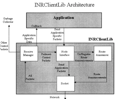
The INRClientLib is composed of three main components that are responsible for carrying out the steps described in Section 3.2: the Node Interface, the Receive
Manager, and the Route Announcer. The three components and how they relate to each other are shown in Figure 3-1. Here is an overview of how these components work together to enable applications to work with INS.
" Node Interface: The Node Interface contains the entire API that is exposed
to the developer. The Node Interface provides a function that the application can use to send packets to an INR. If the application is not registered as a part of the vspace the packet is destined for, the Node Interface handles registration with that vspace. As application packets come into the Receive Manager, the Node Interface forwards these packets to a user-defined callback function in the application. The Node Interface allows the application to hear the service ad-vertisements coming from the INR that the application is peering with. Using these service advertisements, the application can discover services as they join the vspace. When an application wants to send data to a vspace, the Node In-terface is responsbile for contacting the DSR for INR address information. After receiving this information, the Node Interface registers the appliation's name with the Route Announcer which will take care of announcing the application to the vspace.
" Receive Manager: The Receiver Manager handles all incoming packets from
INS. It must determine if a packet needs to be forwarded to the application, to the Node Interface, or to be thrown away. If the packet is destined for the application, the Receive Manager will forward the packet to the application. If the packet is a control message from the INR or DSR that the Node In-terface is waiting on, it will forward the packet to the Node InIn-terface. If the packet is a control packet containing service advertisement, and the application is interested, the Receive Manager will forward the packet to the application.
" Route Announcer: The Route Announcer is responsbile for periodically
ad-vertising the application to the various vspaces it is a member of. As the appli-cation requests to join/drop vspaces, the Node Interface forwards the request to the Route Announcer which then starts or continues service advertisement
to a vspace.
The INRClientLib also provides a function to retrieve the current location from a Location Server colocated on the same machine if one is available. This is to be discussed further in Section 4.4.
3.4
Implementation
The INRClientLib is implemented in both JavaTM [11) and Win32. In the Java implementation, an application inherits from a base class named Node Interface which contains all of the helper functions. The Win32 implementation is written in C and is provided as a DLL, which is used as a shared library. The DLL also exposes all of the helper functions that the Java implementation does. In addition, the INRClientLib provides several helper libraries to help with creating and accessing the various packet formats and intentional names used in the system.
INRClientLib completely abstracts communication to the DSR, INR, or any other application. As packets with new destination names are specified, the INRClientLib will take care of finding an INR that can handle the packet. Once it finds an INR, The Route Announcer will register the application as a neighbor, or more accurately in this case, a client, with the INR. Once connected to the INR, the application can ask the INRClientLib to listen for service announcements that this INR receives. For example, if another client in the same vspace starts up somewhere else in the network, by registering for service announcements, the application will be notified. When packets arrive for the application, the Receiver Manager determines if the packet should go to the application. The INRClientLib delivers any application-specific packets to an application defined callback function to let the application deal
with the packet.
Each application using the INRClientLib will run in its own thread. This thread drives all interaction with the Node Interface. On startup, the Node Interface must be initialized with the location of a DSR. Once this is done, the Node Interface will start up the two helper threads: the Receiver Manager and the Route Announcer.
The Receive Manager is responsible for all incoming packets. The Route Announcer runs in the other thread, and it makes sure that application is a part of any vspace that the application is interested in. The Node Interface maintains a pair of locks around the socket, one for reading and one for writing, which prevent the multiple threads from sending or reading from the socket at the same time.
Chapter 4
Location-Support System
To fully utilize INS as a location-based resource discovery system, we must augment it with a location-support system. The location-support system is responsible for pro-viding location information to any entity which is interested in what their location is. In conjuction, the two can provide location-based services for mobile applications. In Section 4.1, we discuss the design goals for such a system. Section 4.2 shows our architecture for the location support system. In Section 4.3, we look at both imple-mentation details for both the hardware and software involved. In Section 4.4, we look at how we integrate this location support system with INS. Finally in Section 4.5, we analyze the system we have implemented and take a look at the experimental results.
4.1
Design Goals
INS provides a solid framework for our resource discovery needs, but INS requires additional location support to fully utilize its functionality. INS already provides applications the ablity to interact with other applications based on their intentional names. However, these intentional names only provide information about the char-acteristics of the individual application, not the location information relating it to other applications. Our location support system should provide INS applications the ability to discover not only where they are physically located, but to also discover other INS applications based on this location information. For example, suppose a
group of people are in a conference room and need to print something; the print spooler should find the nearest printer based on its location.
Most of the systems described in Section 1.1 rely on a central computer to do some large amount of processing on behalf of the user to resolve the user's location. Our location support system should avoid this dependency on a central computer to avoid single-point-of-failure problems. Also, by creating a distributed location support system, we protect the user's privacy from the centralized systems described in Section 1.1.
The RADAR system from Microsoft [3] solves this problem by moving a database of information from the central computer to the user's computing device. This creates a distributed solution which also protects the user's privacy. However by distributing the database to each user's mobile device, everytime the environment changes, we are required to redo all the off-line measurments. To avoid this, any changes to the environment (e.g., changing the structure of the building) should not require mass redistribution of software or data. Our location support system should protect the user's privacy and not require changes to the client as the environmental conditions change.
Finally, we want our solution to be cost-effective. Only a relatively low-cost solu-tion is viable for wide-scale deployment.
4.2
Architecture
Our system consists of two types of devices: beacons and receivers. The beacons transmit information, which we refer to as packets about the geographic location, and the receivers (located with the user) receive and interpret these packets. Since the beacon is transmitting to the receiver and the receiver does not transmit anything back, the user's privacy is protected. The information in the packets being transmit-ted by the beacons are not hard wired to any particular format; any short string is valid. Hence, any restructuring of a building or of the location namespace will not result in the system going off-line; rather only the values being transmitted from the
locations which are affected by the restructuring will need to be changed.
We place one beacon in every location that we would like to identify using our system. The location does not have to be restricted to only one room. Since we are not aiming for the type of accuracy achieved in a system like the Bat [9, 8], our costs stay low. In addition, by tying each locatable region to a beacon, the failure of any one beacon does not affect the operation of the other beacons.
The receiver which is colocated with the user (or mobile device more accurately) listens to packets from the beacons which it uses to determine its current location. The receiver then sends this information to the mobile device. The device can then use this information to find nearby resources using INS.
The receiver also runs a tiny server, which we will refer to as the receiver server, on the device to which it is connected. This receiver server exposes an API through which applications can learn their location.
The rest of this section discusses how the beacon and receiver interact and the location inference algorithms that run on the receiver server.
4.2.1
Beacon-Receiver Protocol
The beacons transmit packets using a low-cost 418 MHz RF transmitter which can transmit information at 1200 bits/s. The range of this transmitter is approximately 10-12 feet. The receiver has a low-cost RF receiver which can receive data at 1200 bits/s. Each receiver interfaces with any device that supports standard RS232 com-munications.
Since there may be two locations close enough such that their RF transmissions may collide, we try to limit collisions by using randomized transmission. Each packet transmission is separated by a random delay uniformly chosen from the interval [150, 350] ms. Another method to avoid collisions is by using carrier sense multiple access
(CSMA). Using this scheme, the transmitter will actually "sense" whether or not
a transmission is in progress and waits until the transmission is over to transmit. In addition to increasing the complexity of the hardware involved and increasing power consumption, we are interested in detecting which beacon is closer. We are not
interested in reliably detecting every packet being sent out by every beacon.
When a collision does occurs, one of two things will happen. The transmission from the beacon which is farther away maybe be weak (since signal strength varies as some inverse power of distance). Hence, the transmission from the nearby beacon will remain valid. Or, the transmission from the beacon which is farther away will be sufficiently strong enough to corrupt the transmission from the closer beacon. In the second case, the receiver will drop the packet anyway since the checksum will be invalid. One of the two cases result in the proper location being heard by the receiver. Hence, the receiver will be able to determine the proper location given enough time to take a few samples.
4.2.2
Receiver Algorithms
The receiver server runs a simple inference algorithm to determine the correct location from the data coming from the receiver. An inference algorithm is necessary since the data may often be noisy with occasional packets from nearby beacons. The inference algorithm smooths this data out and makes a best-guess estimate to the current location using a mode-based algorithm.
As discussed earlier, there can be two types of collisions that occur. When the two signals are both corrupted, we simply drop the packet. The other type of collision occurs when the packet from the closer beacon is sufficiently stronger than the col-liding packet. In this case, we end up receiving the correct packet. Looking at these two scenarios, the beacon with the most received packets at the receiver will be the correct beacon. The receiver server collects data for a certain of window time. We optimize this window of time by experimentation. Each building will have slightly different RF interference characteristics, hence a few experiments which check what window size is optimal should be conducted to determine the window size. From this window, the receiver will count the number of packets from each beacon and select the location being advertised by the beacon with the highest packet count.
The receiver server provides this functionality so that there is no duplication of effort on the same device. This makes sense since some of these devices may be devices
11 bytes
OF OF OF OF FF 00 05 00 04 01 10
Header Data Checksum
Figure 4-1: A location packet containing the data '0504'
with limited computational power; there is no reason for the same computation to occur multiple times on the same device.
4.3
Implementation
In this section, we describe our implementation of the location support system de-scribed in Section 4.2. In Section 4.3.1 we take a look at the packet format transmitted by a beacon. In Section 4.3.2, we look at the hardware implementation of the beacon
and receiver. We conclude this chapter in Section 4.3.3 with a look at the software running on our hardware and the receiver server.
4.3.1
Packet Format
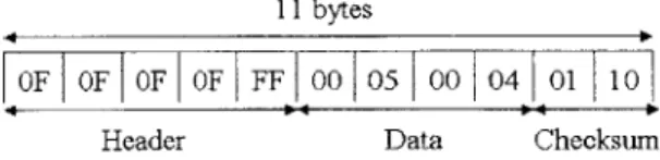
The location packet has a five-byte header consisting of 4 OxOF and 1 OxFF. These five bytes are used to train the microcontroller so its ready to receive the first data byte. In this implementation, all locations were four bytes long (indicating a room number in the laboratory). For error checking, each location was appended with a 2-byte checksum. A sample location packet and its format are shown in Figure 4-1. The checksum is a 2-dimensional XOR. The first checksum byte is an XOR of all the data bytes, i.e., in the "y" direction). The first four bits of the second byte of the checksum correspond to a XOR of the bits of each byte in the payload, i.e., in the
"x" direction).
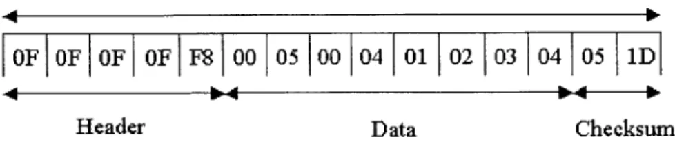
In addition to the location packet, the system also uses a packet not discussed yet called a control packet. The control packet is used for remote management of beacons. The control packet differs slightly from the location packet in the header, the size,
15 bytes
OF OF OF OF F8 00 05 00 04 01 02 03 04 05 1D
Header Data Checksum
Figure 4-2: A control packet containing the data '05041234'
and checksum. The header of the the control packet ends with a OxF8 instead of a OXFF. The payload of the packet is eight bytes long instead of the four in a normal location packet. The checksum is almost the same; instead of throwing away the last four bits of the second checksum byte, they are the "x" direction XOR of the extra four bytes in the payload. A sample location packet and its format are shown in
Figure 4-2.
4.3.2
Hardware
We used the iRX hardware platform [17] for our implementation. We replaced the infrared hardware on the iRX hardware with RF transmitters and receivers [14]. The beacon and receiver both have the same design which makes them interchangeable, and only the software changes. The hardware configuration of both consists of off-the-shelf parts that cost less than US $10.
Each device is controlled by a PIC micro-controller with 68 bytes of RAM and 1024 words of program memory running at 10MHz. Each device has both an RF transmitter and RF receiver. The RF transmitter is a Micro Tx from Low Power Radio Solutions [15], and the RF receiver is from the same company. The transmitter and receiver provide support for serial data in/out. Apart from a few capacitors and voltage regulators, there is an RS-232 signal converter which the device uses to communicate with any serial port. A schematic of the device is shown in Figure 4-3. The device uses a standard 9V battery.
Super RX AM Receiver
TP2
Figure 4-3: Schematic for Location Beacon/Receiver
4.3.3
Software
PIC Microcontroller
The software on the PIC micro-controller coordinates all the components on the hard-ware device. It takes care of sending and receiving RF data, verifying checksums and forwarding valid packets onto the receiver server. The micro-controller can operate in three different modes depending on its function. In addition to the beacon and receiver modes, there is an additional management mode used to configure beacons.
" Beacon Mode
Since beacon's are responsible for advertising location information, the micro-controller must coordinate sending randomized transmissions of the location information out through the RF transmitter. Each micro-controller is pro-grammed with an array of ten random numbers between [150,350]. The micro-controller is also programmed with the short string that represents the location information it is to transmit. Using the random numbers as the interval be-tween transmissions (in ms), the micro-controller randomizes its transmissions of the location information.
" Receiver Mode
The receiver software uses many of the same communication functions that the beacon software uses. The only difference is while it loops, it reads information from the RF receiver rather than transmitting information. It looks for packets following the format described by Figure 4-1. When a packet comes through, the micro-controller will compute the checksum to validate the packet. If the packet is valid, the micro-controller sends the data through the serial port to the receiver server.
" Management Mode
Since it is convenient to wirelessly configure a beacon rather than attaching a se-rial cable to the beacon, we have implemented a management feature. Instead of hard-coding the location information into the controller, the micro-controller merely waits for a control packet from another transmitter, reads the
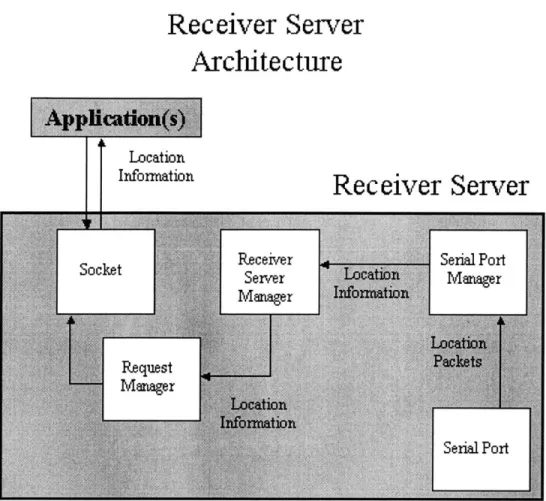
Receiver Server
Architecture
Location
Information
Receiver Server
Figure 4-4: Receiver Server Architecture
location information out of the control packet's payload, and starts transmit-ting that location information. The extra four bytes of payload information in the control packet contain authorization information to validate the location information with. This prevents unauthorized users from changing the location of beacons in the system.
Receiver Server
The receiver server is responsible for processing any information on the serial port coming from the receiver. The receiver server is composed of three main components: Receiver Server Manager, Serial Port Manager, and Request Manager. An architec-tural diagram of the Receiver Server is shown in Figure 4-4. Here is an overview of
how these three components work together to read information from the serial port and deliever it to requesting applications:
" Receiver Server Manager
The Receiver Server Manager is the glue that mediates interactions between the Serial Port Manager and the Request Manager. The Receiver Server Manager starts the other two Managers with initialization information. As location in-formation is passed from the Serial Port Manager to the Request Manager for applications to use, it goes through the Receiver Server Manager which han-dles all of the locks involved in keeping the location information from being corrupted.
" Serial Port Manager
The Serial Port Manager is the most important component of the three that comprise the Receiver Server. The Serial Port Manager is responsible for col-lecting data from the serial port as the receiver sends it location information. The Receiver Server Manager gives the Serial Port Manager a window size in which to collect samples. The Serial Port Manager uses a pair of Location Data objects to collect the data. As each time window finishes, the Location Data object is swapped with the other Location Data object. As soon as a Location Data object is swapped out, the Serial Port Manager uses that data to calcu-late the current location using the mode-based inference algorithm described in Section 4.2.2. This information is passed to the Receiver Server Manager which passes it to the Request Manager as needed.
" Request Manager
The Request Manager is responsible for handling application requests for loca-tion informaloca-tion. The Request Manager actually handles two types of requests. The first type of request is to simply ask for the location as calculated by the
return all the location information collected in the last time window which it gets from the Receiver Server Manager.
The network interface is very simple. The requesting application sends a UDP packet to the Request Manager's socket. The Request Manager has two meth-ods of replying. The first method is the "location only" method which is invoked only when the UDP packet is empty. The second method is the "all location information method" invoked when the UDP packet is non-empty. In the loca-tion only mode, the Request Manager sends back an UDP packet with current location information from the last time window determined by the inference algorithm running in the Serial Port Manager. If the UDP packet is non-empty, the Request Manager will send back all of the location information from the last time window. The information will be two columns, one with the location and one with the number of samples from that location.
4.4
INS Integration
INS integration relies on the INS's notion of vspaces. Since vspaces are the basic construct that INS organizes its services around, we map the vspace name to a location being served by a beacon in our location support system. All services related to a location register with the vspace mapped to that location. Now all services in that location are members of the same vspace which enables location-based service discovery.
An application looking for nearby services (in nearby locations) can use the "all location information method" of the Request Manager in the Receiver Server to find out about nearby locations and join those vspaces also to discover nearby services.
In our implementation, the Receiver Server returns the same location string given to it by the receiver which forwards the packet sent to it by the beacon. Since any service in that location ultimately relies on the beacon for the location string, changing the location string at the beacon does not affect operation of the system.
system has no problem adapting to the new numbering system. All the services in the location will change to the new number just by changing the information in the
beacon servicing that location.
As mentioned in Section 3.3, the INRClientLib provides a function for retrieving the location only information from the Receiver Server running on the same machine (if there is one running on that machine). INRClientLib also provides a convenience function for registration in that location's vspace enabling easy access to location-based service discovery.
4.5
Evaluation
In this section, we take a look at how well our location support system performs in a realistic test environment. Section 4.5.1 discusses the experiment and how to interpret the outcome of the experiment. Section 4.5.2 looks at the results of running the experiment and provides an analysis of these results. Section 4.5.3 looks at other possible solutions to this problem.
4.5.1
Methodology
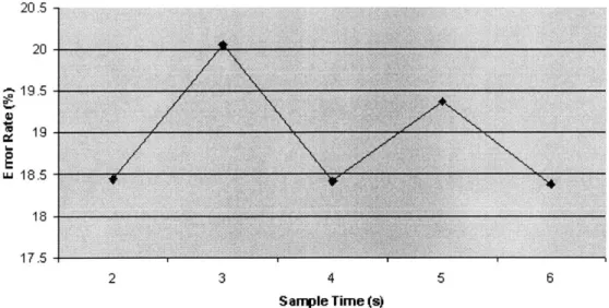
The obvious measure of performance for the location support system is how well it can resolve location using data from a receiver. To do this, we walked back and forth between three rooms and logged each room transition. By keeping track of which room we were in, it was easy to see when the Receiver Server was giving the correct location. We also attempted to find out what the best window size in seconds was for the Serial Port Manager by varying the window size (in seconds). Each time the Receiver Server reported an incorrect location, an error was logged. The error rate is the number of incorrect locations divided by the total number of reported locations.
Error Rates
20.5 -20 19 i.118.5 17.5 2 3 4 5 6 Sample Time (s)Figure 4-5: Location Manager Error Rates
4.5.2
Results and Analysis
The results of the experiment described above are given in Figure 4-5. It is obvious from the results that the error rates are not low enough for this to be a robust system. Why is an RF-only solution difficult to use as a location support system?
One of the main problems with RF is its radiation pattern. Ideally, we expect the radiation pattern to radiate equally in all directions from the antenna in a sense bathing the entire room with radio waves, but this is not the case. There are many factors which affect the RF signal. Common office items such as monitors and com-puters can generate RF interference which distort the RF transmissions. There are also a number of other sources of interference. In addition, depending on where the receiver is placed with respect to the beacon, the transmission power at that location can be an order of magnitude different from a location just a few feet away. Figure 4-6 shows the radiation pattern of a straight antenna. Notice that at around 120 degrees and 300 degrees, the transmission power is significantly lower than other positions. Therefore, if the receiver's position is in a dark spot of the current room, but not


![Figure 4-6: Radiation Patterns of a Straight Antenna [20]](https://thumb-eu.123doks.com/thumbv2/123doknet/14751540.580425/39.918.227.653.151.568/figure-radiation-patterns-straight-antenna.webp)
