Publisher’s version / Version de l'éditeur:
Chemistry of Materials, 29, 21, pp. 9579-9587, 2017-10-17
READ THESE TERMS AND CONDITIONS CAREFULLY BEFORE USING THIS WEBSITE.
https://nrc-publications.canada.ca/eng/copyright
Vous avez des questions? Nous pouvons vous aider. Pour communiquer directement avec un auteur, consultez la
première page de la revue dans laquelle son article a été publié afin de trouver ses coordonnées. Si vous n’arrivez pas à les repérer, communiquez avec nous à PublicationsArchive-ArchivesPublications@nrc-cnrc.gc.ca.
Questions? Contact the NRC Publications Archive team at
PublicationsArchive-ArchivesPublications@nrc-cnrc.gc.ca. If you wish to email the authors directly, please see the first page of the publication for their contact information.
NRC Publications Archive
Archives des publications du CNRC
This publication could be one of several versions: author’s original, accepted manuscript or the publisher’s version. / La version de cette publication peut être l’une des suivantes : la version prépublication de l’auteur, la version acceptée du manuscrit ou la version de l’éditeur.
For the publisher’s version, please access the DOI link below./ Pour consulter la version de l’éditeur, utilisez le lien DOI ci-dessous.
https://doi.org/10.1021/acs.chemmater.7b04221
Access and use of this website and the material on it are subject to the Terms and Conditions set forth at
Ultrathin carbon-coated Pt/carbon nanotubes: a highly durable
electrocatalyst for oxygen reduction
Tong, Xin; Zhang, Jianming; Zhang, Gaixia; Wei, Qiliang; Chenitz, Régis;
Claverie, Jerome P.; Sun, Shuhui
https://publications-cnrc.canada.ca/fra/droits
L’accès à ce site Web et l’utilisation de son contenu sont assujettis aux conditions présentées dans le site LISEZ CES CONDITIONS ATTENTIVEMENT AVANT D’UTILISER CE SITE WEB.
NRC Publications Record / Notice d'Archives des publications de CNRC:
https://nrc-publications.canada.ca/eng/view/object/?id=37a31bdf-776a-4f2b-b9e8-5ab435c83d8d https://publications-cnrc.canada.ca/fra/voir/objet/?id=37a31bdf-776a-4f2b-b9e8-5ab435c83d8d
Ultrathin Carbon-Coated Pt/Carbon Nanotubes: A Highly Durable
Electrocatalyst for Oxygen Reduction
Xin Tong,
†,⊥Jianming Zhang,
*
,‡Gaixia Zhang,
†Qiliang Wei,
†Régis Chenitz,
†Jerome P. Claverie,
*
,§and Shuhui Sun
*
,††
Institut National de la Recherche Scientifique-Énergie Matériaux et Télécommunications, Varennes, Quebec, Canada J3X 1S2
‡
School of Chemistry and Chemical Engineering, Jiangsu University, Zhenjiang, China 212013
§
Department of Chemistry, Université de Sherbrooke, Sherbrooke, Quebec, Canada J1K 2R1
⊥
School of Chemistry and Material Science, Guizhou Normal University, Guiyang, China 550001
*
S Supporting InformationABSTRACT: Nanostructures constituted of Pt nanoparticles (NPs) supported on carbon materials are considered to be among the most active oxygen reduction reaction (ORR) catalysts for fuel cells. However, in practice, the usage of such ORR catalysts is limited by their insufficient durability caused by the low physical and chemical stability of Pt NPs during the reaction. We herein present a strategy to synthesize highly durable and active electrocatalysts composed of Pt NPs supported on carbon nanotubes (CNTs) and covered with an ultrathin layer of graphitic carbon. Such hybrid ORR catalysts were obtained by an interfacial in situ polymer encapsulation−
graphitization method, where a glucose-containing polymer was grown directly on the surface of Pt/CNTs. The thickness of the carbon-coating layer can be precisely tuned between 0.5 nm and several nanometers by simply programming the polymer growth on Pt/CNTs. The resulting Pt/CNTs@C with a carbon layer thickness of ∼0.8 nm (corresponding to ∼2−3 graphene layers) showed high activity, and excellent durability, with no noticeable activity loss, even after 20 000 cycles of accelerated durability tests. These ultrathin carbon coatings not only act as a protective layer to prevent aggregation of Pt NPs but they also lead to better sample dispersion in solvent which are devoid of aggregates, resulting in a better utilization of Pt. We envision that this polymeric nanoencapsulation strategy is a promising technique for the production of highly active and stable ORR catalysts for fuel cells and metal−air batteries.
■
INTRODUCTIONProton exchange membrane (PEM) fuel cells are one of the most promising clean energy devices to convert chemical energy into electricity via a sustainable process.1−4 However,
their performance is highly dependent on the sluggish kinetics of the cathodic oxygen reduction reaction (ORR) process, which itself is determined by the efficiency of the electro-catalyst.5−7 Platinum (Pt) nanoparticles (NPs) dispersed on
carbon materials are currently considered as the best ORR catalysts.8,9Despite their popularity, there are still many issues that are yet to be addressed before reaching large-scale commercial implementation. Notably, the insufficient stability of such Pt catalyst significantly curtails the lifetime and durability of PEM fuel cells. On the other hand, in direct methanol fuel cells (MDFCs), methanol can diffuse from anode to cathode through the membrane, which can lead to cathode depolarization and thus to a significant reduction of the overall cell potential due to the methanol oxidation reaction on Pt.10,11 Thus, extending the lifetime and enhancing methanol tolerance of the cathode catalyst without reducing its activity and without
considerably increasing its cost remains a critical issue in the development of PEM fuel cells.
In PEM fuel cells, the ORR catalyst operates under harsh conditions (highly positive potentials and strongly acidic media) and the electrochemical surface area (ECSA) of Pt is lost during cycling, due to Ostwald ripening, dissolution and aggregation of the Pt NPs, as well as the corrosion and oxidation of the carbon support.12 One of the effective strategies to improve the durability of Pt catalysts is to employ novel supporting materials.13 For example, hollow core− mesoporous shell carbon,14 mesoporous carbon,15 ordered hierarchical nanostructured carbon,16colloid-imprinted carbon supports,17 graphene,9,18and carbon nanotubes (CNTs)19−21
have been examined as alternatives to Vulcan XC-72, a commercial carbon black which is often used as benchmark support.22 Among those, CNTs have shown encouraging
Received: October 6, 2017
Revised: October 16, 2017
Published: October 17, 2017
pubs.acs.org/cm
Cite This: Chem. Mater. 2017, 29, 9579-9587
results that have been correlated with their high conductivity, high surface area, and excellent chemical resistance.19,21
Another successful strategy consists of protecting the Pt NPs in a shell.11,23−33With the help of this protective layer, the Pt
NPs are less prone to agglomerate or to detach from the support under highly oxidizing conditions. Among those, carbon shells have shown to prolong the catalyst life-time,11,24,26,28,29,33,34 but with highly variable results which can be explained by the fact that too thin carbon-coating layers are not effectively protecting the Pt NPs while too thick ones are blocking the effective active surface of Pt.28In this report, we designed a highly durable and active ORR catalyst by combining the excellent properties endowed by CNTs as support and the protective action of ultrathin graphitic carbon layers with controlled thickness. Thus, Pt NPs supported on CNTs and encapsulated in carbon layers (Pt/CNTs@C) were prepared by a facile in situ polymeric encapsulation− graphitization method which allowed precise control over carbon thickness as well as a solid anchoring of the Pt NPs at the surface of the CNTs (Scheme 1). Electrochemical evaluations indicate that the electrocatalytic activity strongly depends on the thickness of the carbon-coating layers. Once optimized, the thin coating around Pt/CNTs effectively inhibits the Pt catalyst aggregation or dissolution during cycling, while maximizing reagent mass transport. Thus, the Pt/CNTs@C composite combines high durability and catalytic activity in ORR. It also shows a high methanol tolerance, overcoming the loss of ORR activity of Pt/CNTs in the presence of methanol.
■
EXPERIMENTAL SECTIONMaterials.CNTs (multiwall, several hundred nanometers in length and 15−30 nm in diameter) were purchased form Bayer. Formic acid (HCOOH, 98%), hexachloroplatinic acid (H2PtCl6·6H2O, 99.95%),
4,4′-azobis (4-cyanovaleric acid) (ABV, >75%), sodium lauryl sulfate (SDS), and styrene (99.9%) were all purchased from Sigma-Aldrich. Reversible addition−fragmentation chain transfer (RAFT) polymer-ization agent poly(acrylic acid)(butyl acrylate) (PABA) was synthesized previously in our laboratory.35−37
Synthesis of Pt NPs Supported on Carbon Nanotubes (Pt/ CNTs). Pt/CNTs were obtained by the chemical reduction of Pt precursor with formic acid (as shown inScheme 1).37Typically, 10 mg
of CNTs was dispersed in 4 mL of H2O and mixed ultrasonically for
∼1 h. Then 0.5 mL of formic acid and 2 mL of hexachloroplatinic acid
solution (1 mgPtmL−1) were added to the above suspension. The
mixture was stirred at 80 °C for 30 min until the solution turned from golden-orange to colorless transparent. The as-prepared product was washed three times with water and collected by centrifugation. Then the Pt/CNTs (Pt: 17 wt %) were dried in a vacuum oven at 60 °C for 12 h.
Synthesis of Pt/CNTs Coated with Carbon Layer (Pt/CNTs@ C). The synthesis of N-acryloyl-D-glucosamine (AGA) and of the
RAFT agent PABA containing 10 acrylic acid units and 5 butyl acrylate units were reported previously.35−37The polymer encapsulation of Pt/
CNTs was achieved as follows: typically, 40 mg of Pt/CNTs and 20 mg of PABA were dispersed into 8 mL of water and sonicated with 30% amplitude for 5 min (Fisher Scientific sonic dismembrator 500, 400 W) to yield a black stable Pt/CNTs@PABA suspension. Then 10 mg of ABV initiator was added to the above solution. Meanwhile, 300 mg of AGA, 200 mg of styrene, and 10 mg of SDS were added to 8 mL of water, and the resulting emulsion was degassed with N2for 30 min.
Then a syringe (50 mL) was filled with the emulsion and fixed to a syringe pump connected to the Pt/CNTs@PABA dispersion. The Pt/ CNTs@PABA dispersion was heated at 80 °C under magnetic stirring and the monomers were added in under a N2 atmosphere over a
period of 5 h. Then the dispersion was kept at 80 °C for another 2 h to complete the polymerization. The encapsulated Pt/CNTs was collected by centrifugation and dried in a vacuum oven. The product was then heated under a N2atmosphere at 550 °C for 3 h.
Characterizations. Transmission electron microscopy (TEM) observations were conducted with a JEOL JEM-2100F microscope equipped with a field emission gun running at 200 kV. X-ray diffraction (XRD) patterns were recorded with Bruker D8 Advance with Cu Kα as an X-ray source. Thermogravimetric analysis (TGA) was performed under an air atmosphere with a heating rate of 4 °C min−1on a MS
coupled thermogravimetric analyzer (TA Instruments TGA Q500/MS Discovery). X-ray photoelectron spectroscopy (XPS) was measured with a VG Escalab 220i-XL using Mg Kα line as an excitation source. Electrochemical Characterizations.An Autolab electrochemical system (Model, PGSTAT-302, Ecochemie, Brinkman Instruments) was used to characterize the electrochemical properties of the corresponding samples. In a three-electrode system, a glassy carbon rotating disk electrode was used as the working electrode, a Pt wire was used as the counter electrode, and a saturated calomel electrode was used as the reference electrode. All potentials in this study were referred to reversible hydrogen electrode (RHE). The catalyst ink was prepared as follows: 5 mg of catalyst was mixed with 50 μL of deionized water, 1650 μL of ethanol, and 85 μL of 5 wt % Nafion solution (in lower aliphatic alcohols and water) followed by 30 min of ultrasonication. Then 7 μL of the catalyst suspension was pipetted Scheme 1. Synthetic Process of Pt/CNTs@C and the Corresponding Reaction at Each Step
Chemistry of Materials Article
DOI:10.1021/acs.chemmater.7b04221 Chem. Mater. 2017, 29, 9579−9587
onto the polished gas chromatograph (Pine Research Instrument, diameter 5 mm, 0.196 cm2,) to maintain a Pt loading of about 20 μg
Pt
cm−2 for all tests. Then the working electrode was dried at ambient
conditions before being immersed in a 0.1 M HClO4 solution. The
electrochemical measurements were all conducted at room temper-ature. Initially, 50 potential cycles between 0.04 and 1.2 V (scan rate = 100 mV s−1) were completed to make sure that the surface of the
working electrode was clean. Cyclic voltammograms (CVs) of all the catalysts were measured between 0.04 and 1.2 V (scan rate = 50 mV s−1) in a N
2-saturated HClO4 (0.1 M) solution. The polarization
curves for the ORR on the samples were performed between 0.04 and 1.2 V (scan rate = 10 mV s−1) in an O
2- or N2-saturated HClO4(0.1
M) with an electrode rotation rate of 1600 rpm. Then the net Faradaic current was obtained by subtracting the voltammogram recorded under N2from the one recorded under O2. Accelerated durability tests
(ADT) were carried out by potential cycling in a square wave between 0.6 and 1.2 V in N2-purged 0.1 M HClO4(scan rate = 200 mV s−1).
To calculate the ECSA of Pt, the following equation was used: =
Q m q
ECSA H
Pt H
where QH is the charge for hydrogen adsorption region, mPtis the
weight of Pt (mg) on the working electrode, and QHis constant (0.21
mC cm−2) corresponding to the charge required for monolayer
adsorption of hydrogen on Pt surface.38
■
RESULTS AND DISCUSSIONPreparation of Pt/CNTs@C Composite.The Pt/CNTs@ C nanostructures were synthesized via an in situ polymer nanoencapsulation method, followed by a graphitization process. As presented in Scheme 1, Pt NPs are first formed at the surface of the CNTs through the reduction of H2PtCl6by
HCOOH (Step (i)). The encapsulation of Pt/CNTs begins with the adsorption of the PABA RAFT dispersant constituted of acrylic acid and butyl acrylate units onto the CNTs surface via noncovalent interactions. The PABA molecules adsorbed on Pt/CNTs act as spacers which obstruct the formation of π−π interactions between CNTs, allowing the uniform and stable dispersion of Pt/CNTs in water (see Figure S1 of the Supporting Information, and our previous reports).36,37 After-ward, upon the introduction of the monomers, an in situ growth of polymer chain occurs at the Pt/CNT surface via RAFT polymerization (Step (ii)). As the RAFT process is a so-called controlled polymerization process, the newly formed polymer extends the RAFT dispersant chain, resulting in the formation of a block copolymer. Because the active RAFT dispersant is anchored at the surface of the Pt/CNTs, the hydrophobic block constituted by the newly formed polymer can effectively grow into a continuous polymer shell encapsulating the Pt/CNTs. Because the initial dispersion of PtCNTs is devoid of aggregates, the encapsulation occurs in a 1:1 fashion, leading to the formation of Pt/CNT@polymer coaxial structures. Herein, a special monomer, N-acryloyl-D
-glucosamine (AGA), was used to form the shell as it contains a glucosamine unit which is a carbon source. However, the resulting glucosamine polymer tends to desorb from the CNTs surface as it is water-soluble. Therefore, a mixture of AGA and hydrophobic styrene (S) (Step (ii)) was selected to form the copolymer shell. Because the amount of monomers (S + AGA) is much larger than the RAFT dispersant one, the asymmetric block copolymer is constituted of a long hydrophobic block, PSAGA, and a short surface-active block (the RAFT dispersant). The encapsulation process is exceedingly efficient as every Pt NP and CNT are trapped in a continuous shell of copolymer to form a Pt/CNTs@PSAGA structure (confirmed
by TEM, Figure 1, see below). The uniform glucose polymer layer laid the foundations of the next step. After being annealed
at 550 °C under N2 atmosphere, the polymer layer was
pyrolyzed into a graphitic carbon shell (Step (iii)).
Structure Characterization. The morphologies of the nanostructures at each synthetic step were investigated by TEM.Figure 1a,b shows the TEM images of the Pt/CNTs at different magnifications. Clearly, the Pt NPs are uniformly distributed at the CNTs surface. After polymer encapsulation, as shown in Figure 1c,d, a continuous and uniform polymer coating with a thickness of ∼5−8 nm is formed around each CNT, and the well-separated Pt NPs are completely embedded in the polymer (Figure 1d), indicating the successful encapsulation. After thermal annealing, the polymer layer is transformed into graphitic carbon layer covering all around the Pt/CNTs (Pt/CNTs@C). As displayed in the TEM images (Figure 1e,f), no significant aggregation of Pt NPs can be observed after annealing. High-resolution TEM (HR-TEM) image (inset of Figure 1f) further shows that each Pt NP is completely covered by a continuous graphene-like carbon coating with a thickness of ∼0.8 nm, corresponding to 2−3 graphene layers. The particle size of the Pt NPs was measured at each synthetic step (Figure 1g). Remarkably, the size of Pt NPs remains nearly unchanged, with a slight increase from ∼2.4 to 3.6 nm due to the heat treatment. By contrast, when Pt/ CNTs composite (no polymer coating) is annealed under the same conditions, the size of the Pt NPs reaches ∼6.7 nm (Figure S3). These results indicate that the carbon coating is efficiently protecting the Pt NPs from the coarsening process which is usually associated with a loss of catalytic activity in ORR.
As illustrated inScheme 1, when the amount of monomers is increased, the final copolymer chain becomes longer, resulting in a thicker carbon coating due to a higher content of glucose Figure 1.TEM images of Pt/CNTs (a, b) and PSAGA-encapsulated Pt/CNTs before (c, d) and after (e, f) graphitization. Inset of (f) shows the HR-TEM image of Pt/CNTs@C. (g) Corresponding Pt NP size variation of all nanohybrids at different synthetic steps. The size distributions of Pt were analyzed by randomly selecting 100 NPs to measure their diameters.
unit. Thus, the thickness of the carbon coating can be precisely controlled by tuning the amount of added monomer.34Table 1
lists the composition of the various Pt/CNT@C composites. The samples were analyzed by TEM investigations to assess the thickness of the C coating layer.Figure 2 presents the TEM
images of the corresponding Pt/CNT@C composites listed in
Table 1. The average thickness of the carbon coating gradually increased from 0.5 nm (a) to ∼0.8 nm (b), ∼1.5 nm (c), and ∼2 nm (d) as the monomer amount increased, which is consistent with the controlled nature of the RAFT polymer-ization. Observations by HR-TEM indicate that the carbon coating is composed of distorted graphite-like carbon segments containing between a single (a) to ∼5 graphene layers (d). However, for Pt/CNTs@C-1 (a), the carbon coverage is not complete, and bare Pt surface can be observed occasionally (arrows in Figure 2a). In this case, the size of the Pt NPs is augmented during annealing (∼4.5 nm in diameter, seeFigure S2), which is consistent with the insufficient polymer protection.
Thermogravimetric analysis (TGA) further confirms the content of carbon coating on Pt/CNTs@C sample.Figure 3
shows the TGA curves of the Pt/CNT sample with (red) and without (black) carbon coating (∼0.8 nm of thickness, Pt/ CNTs@C-2). As reported, different oxidation behaviors can be observed in different structural forms of carbon,40 and a less ordered carbon form tends to be oxidized at a lower temperature, whereas a well-graphitized structure is more
stable.39For both samples, a sharp weight loss occurred from ∼450 up to 500 °C which could be assigned to the oxidation of CNTs.39For Pt/CNTs@C sample, an additional weight loss of ∼6.5% appeared at the lower temperature region between 300 and 400 °C, which corresponds to the oxidation of the disordered graphene-like carbon coating. This relatively high weight loss indicates that the carbon layer not only covers the Pt NPs but also the CNTs (such layer is not visible by TEM because it is carbon over carbon).
The crystallinity of Pt/CNTs and Pt/CNTs@C was assessed by XRD. As shown in Figure 4a, both Pt/CNTs and Pt/ CNTs@C composites show a well-crystallized Pt and graphitic carbon structure. The four major diffraction peaks at ∼39.8°, 46.3°, 67.5°, and 81.4° correspond to the (111), (200), (220), and (311) planes of the face-centered cubic (fcc) Pt (JCPDS No. 04-0802).29The peak at ∼25.5° can be assigned to the (002) diffraction of the graphitic carbon in CNTs.41 After carbon coating (red), the Pt peaks become more narrow, indicating an increase of crystallinity. A decrease of the peak intensity ratio of the graphite (002) to Pt (111) is also observed, perhaps due to the less ordered structure of carbon coating compared to CNTs, which is consistent with the TGA analysis.
Surface chemistry variations of the Pt/CNTs samples with and without a carbon coating were examined using XPS.Figure 4b shows the Pt 4f spectra of the samples before and after carbon coating. Both samples show the two typical peaks at high and low binding energy respectively corresponding to Pt 4f5/2and Pt 4f7/2. The Pt 4f signals can be deconvoluted into
three doublets which can be assigned to the Pt0state (red line),
Pt2+state (blue line), and Pt4+ state (green line).25,28 The
abundance of the three oxidation states is not affected by the presence of the carbon coating, indicating that that Pt remains unchanged during the coating process. However, a slight shift of ∼0.2 eV of Pt to higher binding energy (BE) is detected in Pt/CNTs@C compared to Pt/CNTs. The increase in Pt BE in Pt/Cthat NTs@C may result in slightly weaker Pt−O binding in comparison to that of Pt/CNT samples, an effect which has Table 1. Recipe for the Synthesis of Carbon-Coated Pt Supported on CNTs with Different Thicknesses
sample Pt/CNTs (g) PABA (g) ABV (g) styrene (g) AGA (g) SDS (g) C-coating thickness (nm)
Pt/CNTs@C-1 0.04 0.02 0.02 0.1 0.15 0.005 ∼0.5
Pt/CNTs@C-2 0.04 0.02 0.02 0.2 0.3 0.01 ∼0.8
Pt/CNTs@C-3 0.04 0.02 0.02 0.4 0.6 0.02 ∼1.5
Pt/CNTs@C-4 0.04 0.02 0.02 0.8 1.2 0.04 >2
Figure 2. TEM images of Pt/CNTs@C samples prepared using different amounts of monomers. (a−d) Images correspond to the Pt/ CNTs@C-1 to -4, respectively, listed inTable 1. Insets show the HR-TEM images.
Figure 3.TGA curves of Pt/CNTs and Pt/CNTs@C with a carbon coating of ∼0.8 nm (Pt/CNTs@C-2 inTable 1).
Chemistry of Materials Article
DOI:10.1021/acs.chemmater.7b04221 Chem. Mater. 2017, 29, 9579−9587
been reported to lead to an improvement of ORR rates by inhibiting the formation of surface Pt oxides.42,43
Electrochemical Properties. Cyclic voltammetry (CV) experiments were conducted to estimate the electrochemical performance of as-prepared material and the effects of the carbon layer on the catalytic performance. During the preparation of catalyst ink, the dispersion of Pt/CNTs in water is not colloidally stable, leading to nonuniform electrodes. However, after carbon coating, a uniform dispersion of Pt/ CNTs@C was readily obtained (Figure S4) which likely originates from the fact that the samples are prepared by carbonization of well-dispersed Pt/CNTs@polymer sample. As shown in Figure 5, the CV curves of all catalysts present the typical characteristic features of the monolayer hydrogen adsorption (Hads) and desorption (Hdes) on Pt surface and of
the formation/reduction of Pt−OH and Pt−O groups. However, for the samples with carbon coating (b−e), the peaks of Hads/Hdesare generally much lower in height and less
well-defined compared with those of pure Pt/CNTs (a). With the increase of carbon-coating layer thickness (samples listed in
Table 1), the intensity of the peak of Hdesand Hadsis decreased
(f). For Pt/CNTs@C-1, the lower activity can be ascribed to the larger Pt particle size.44For Pt/CNTs@C-4, the Hdesand
Hadsalmost disappeared, indicating that the carbon layer is too
thick and hinders the ORR and causes more sluggish kinetics. Besides, the Pt oxides reduction peak around 0.8 V has also nearly disappeared. By contrast, the Pt/CNTs@C-2 shows a more obvious Hdes/Hads and Pt oxidation/reduction peaks
compared with other carbon-coated materials, revealing a higher exposed Pt surface.
The accelerated durability test (ADT) is a convenient method to evaluate the stability of the electrocatalysts in an accelerated fashion.38InFigure 5a, the catalytic performance of Pt/CNTs is deteriorated during the test, as shown by the obvious ECSA loss after 3000 cycles. In contrast, the performance of Pt/CNTs@C (b−e) is more stable. The ECSAs in the first cycles are always the smallest, which may be due to the prolonged time necessary to activate the catalyst. Once activated, the CV curves of the catalysts do not show significant change over time, suggesting that the carbon layer protects the Pt NPs during ADTs. Thus, the carbon coatings exert two antagonistic effects on the ORR as it can improve the stability, but also reduce the catalytic activity more or less, depending on the layer thickness. Therefore, precisely controlling and optimizing the carbon-coating thickness is highly desirable, yet remains a great challenge.
By integration of the charge in the hydrogen adsorption region (0 ≤ V ≤ 0.3 V), ECSA can be estimated to evaluate the catalyst properties. After the first cycle (Figure 5f, also see
Table S1), the ECSA of Pt/CNTs and Pt/CNTs@C-(1−4) are found to be 75, 33, 64, 35, and 11 m2/g, respectively. Except for
Pt/CNTs@C-1, the ECSA decreases with the increase of carbon-coating thickness because the carbon layer acts as an obstacle for the catalysis reaction. The ECSA value of Pt/ CNTs@C-2 is comparable to that of Pt/CNTs, suggesting that the hindrance caused by the carbon layer in this catalyst is minimized. The low ECSA value for Pt/CNTs@C-1 is mainly attributed to the larger size of Pt NPs caused by the annealing Figure 4.XRD patterns (a) and XPS spectra (b) of Pt/CNTs and Pt/
CNTs@C.
Figure 5.CV curves of different cycles on Pt/CNTs (a), Pt/CNTs@ C-1 (b), Pt/CNTs@C-2 (c), Pt/CNTs@C-3 (d), and Pt/CNTs@C-4 (e). (f) CVs of the first cycle for all samples. CVs were recorded in N2
process at 550 °C but without sufficient carbon layer protection.
The alteration of ECSA as a function of cycle numbers is summarized inFigure 6. For Pt/CNTs, a sharp drop of ECSA
takes place after 3000 cycles, with only 50% of the initial ECSA remaining. By contrast, for Pt/CNTs@C samples, no obvious changes (except for the first cycle as mentioned above) occurred after 3000 cycles of ADT. Impressively, after 1000 cycles of ADT, the ECSA of Pt/CNTs@C-2 is significantly larger (2 to 4 times) than those of pristine Pt/CNTs and other carbon-coated samples. The increase in ECSA over time for all carbon-coated samples can be attributed to the slight corrosion of the carbon layer, leading to a gradual exposition of fresh Pt surface.28 Thus, a carbon-coating thickness of ∼0.8 nm (Pt/ CNTs@C-2, Figure 5c) offers the optimal compromise between activity and durability.
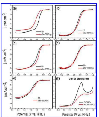
Figure 7shows the typical ORR linear sweep voltammetries (LSVs) for all samples under identical experimental conditions. The best catalyst should exhibit the highest possible value of half-wave potential (E1/2) and current values at 0.80 V (vs
RHE) (see Table S2for details). The sample Pt/CNTs@C-4 shows the lowest values before and after ADT testing, indicative that the carbon layer is too thick. Initially (before ADT testing), the “best” catalyst (based on E1/2, and current value at 0.80 V)
is the Pt/CNTs catalyst. However, after 3000 cycles, the trend is clearly reversed; compared to Pt/CNTs, the Pt/CNTs@C-2 shows much higher E1/2 potential (0.84 V vs 0.76 V) and
current density at 0.80 V (3.1 vs 1.4 mA/cm2). The activity of
Pt/CNTs@C-2 catalyst after 3000 ADT is still lower than the initial activity of the state-of-the-art Pt/C catalyst,45−48 and
more work is underway to improve the activity of this highly stable catalyst. Remarkably, the E1/2 potential and current
values of Pt/CNTs@C have increased during ADT testing, whereas those of Pt/CNTs decrease (by more than 50% for the current density), clearly indicating the protective role of the carbon coating. These results confirm that the Pt/CNTs@C-2 catalyst has a much better lifetime performance. In addition, the ORR performance of Pt/CNTs and Pt/CNTs@C-2 catalysts in the presence of CH3OH are shown inFigure 7f. In the presence
of methanol, there are obvious anodic peaks for methanol oxidation reaction (MOR) at around 0.8 V (vs RHE) in the ORR polarization curves for all samples. Therefore, there are competitions between the ORR and MOR for all catalysts.10 Interestingly, Pt/CNTs@C-2 shows much smaller current
density for MOR than that for Pt/CNTs, indicating the much better methanol tolerance of the former catalyst. This is because the carbon shell could reduce/block the adsorption of methanol on the Pt surface.
TEM analyses were conducted for samples after 3000 cycles of ADT.Figure 8a shows that Pt NPs in Pt/CNTs (initial size 2.4 nm) agglomerated into irregular larger NPs of size ∼11.5 nm. By stark contrast, no obvious aggregation is observed for Pt NPs in Pt/CNTs@C-2 (Figure 8b, 3.9 nm after ADT vs 3.6 nm Figure 6.ECSA as a function of reaction cycles for Pt/CNTs and Pt/
CNTs@C-(1−4). The values of ECSA were calculated from the Hads/
Hdescharge in CVs.
Figure 7.LSVs on Pt/CNTs (a), 1 (b), Pt/CNTs@C-2(c), Pt/CNTs@C-3 (d), and Pt/CNTs@C-4 (e) (before and after ADT test, 3000 cycles). (f) Pt/CNTs and Pt/CNTs@C-2 in the presence of 0.5 M methanol. LVs were recorded in O2-saturated 0.1 M
HClO4(10 mV s−1, room temperature).
Figure 8.TEM images and the size distribution of Pt NPs of Pt/CNTs (a), Pt/CNTs@C-2 (b) after ADT.
Chemistry of Materials Article
DOI:10.1021/acs.chemmater.7b04221 Chem. Mater. 2017, 29, 9579−9587
before ADT). This observation is consistent with all electro-chemical tests, and confirms that the Pt/CNTs@C-2 is more electrochemically stable than the unmodified Pt/CNTs catalyst. The TEM images (Figure 8) also indicate that Pt/CNTs@C is less aggregated (better dispersion in solvent) than Pt/CNTs without carbon coating. Indeed, during the polymer nano-encapsulation step, the carbon nanotubes are dispersed in water, forming a stable, homogeneous, and aggregate-free dispersion.21
Furthermore, we evaluated the stability of Pt/CNTs@C-2 catalyst by a continuous 20 000 potential cycling ADT test. As shown inFigure 9a,b,with cycling, the ECSA of Pt/CNTs@C-2
catalyst gradually increases due to the corrosion of the carbon coating and increased exposure active sites of Pt NPs. Interestingly, the ECSA reaches a plateau (∼85 m2/g) at
2000 cycles and it remains stable for 10 000 cycles, indicating the important role of carbon layer in preventing the aggregation of PtNPs. Even after extended 20 000 cycles, the ECSA is still ∼64 m2/g which is close to the initial ECSA, and represents
only a 25% loss compared to the plateau value. In sharp contrast, the ECSA of Pt/CNTs decreases continuously over time, as shown inFigure. 9c,d. Moreover, after 10 000 cycles, the ECSA of Pt/CNTs is only 27 m2/g, which indicates a
∼64% loss of its initial ECSA. In this test, Pt/CNTs@C-2 clearly demonstrates extremely high durability due to carbon coating.
On the basis of the above results, a possible mechanism for the significantly enhanced durability is proposed. In general, the size increase of the pristine Pt NPs is due to the Ostwald ripening.12,26The thin carbon layer wrapped on the Pt NPs not only acts as a protective layer but also acts as a barrier between catalytic sites and reactants. The thickness of the disordered graphitic layer of carbon plays a key role in controlling the electrocatalytic performance.34 A carbon coating of ∼0.8 nm average thickness (Pt/CNTs@C-2, Scheme 2, left) is permeable to oxygen molecules without hindering the mass transport of molecular oxygen and the contact between oxygen and the catalyst surface. In addition, such carbon coating is
sufficiently thick to prevent Pt NP dissolution or detachment from the CNT surface. Furthermore, it can reduce the adsorption of methanol (the methanol molecule is too large) on the Pt surface and shows higher tolerance to methanol. While, when the carbon coating is too thick, as depicted on the right part of Scheme 2, the oxygen molecules cannot easily reach the surface of the catalyst. In this case, the carbon layer mainly works as an obstacle for ORR, therefore resulting in a lower activity of the catalyst.
■
CONCLUSIONSWe have developed a facile in situ polymer nanoencapsulation− graphitization method to prepare carbon-coated catalysts (Pt/ CNTs@C). The thickness of the carbon coating can be precisely controlled by varying the amount of added monomer, and the optimal thickness for ORR catalysis has been explored. This in situ polymeric encapsulation−graphitization method leads to materials which are devoid of macroscopic aggregates (seeFigure 1and8), thus overcoming the tendency of CNTs to bundle and to resist homogeneous deposition. Remarkably, after 20 000 cycles of ADT, the electrocatalytic activity of the Pt/CNTs @C sample with 0.8 nm carbon coating is comparable to the initial ECSA of Pt/CNTs before ADT cycling, demonstrating that proper carbon coating can significantly improve the stability of the Pt-based catalysts. Furthermore, it also shows a high tolerance to methanol after coating with carbon layer. As it is a facile, easily scalable, and environmentally benign approach, this polymeric nanoencap-sulation strategy is a promising technique for the design of highly active and stable Pt-based catalysts for ORR in fuel cells or to other electroactive devices.
■
ASSOCIATED CONTENT*
S Supporting InformationThe Supporting Information is available free of charge on the
ACS Publications website at DOI: 10.1021/acs.chemma-ter.7b04221.
Optical images of catalyst dispersions, TEM images (PDF)
■
AUTHOR INFORMATION Corresponding Authors *E-mail: zhangjm@ujs.edu.cn(J.Z). *E-mail: jerome.claverie@usherbrooke.ca(J.C.). *E-mail: shuhui@emt.inrs.ca(S.S.). ORCID Jianming Zhang: 0000-0002-7752-1192 Figure 9.Long-term performance on CV curves of Pt/CNTs@C-2 (a)and Pt/CNTs (c). ECSA as a function of reaction cycles for Pt/ CNTs@C-2 (b) and Pt/CNTs (d). CVs were recorded in N2
-saturated 0.1 M HClO4.
Scheme 2. ORR Reaction Taking Place on Pt/CNTs@C Samples with Different Carbon-Coating Layers
Jerome P. Claverie:0000-0001-7363-1186 Shuhui Sun: 0000-0002-0508-2944
Notes
The authors declare no competing financial interest.
■
ACKNOWLEDGMENTSThe authors would like to acknowledge funding from the Natural Sciences and Engineering Research Council of Canada and Fonds de la Recherche du Québec sur la Nature et les Technologies (FRQNT), Centre Québécois sur les Materiaux Fonctionnels (CQMF), the Canada Research Chair program. J.Z. and Q.W. would like to thank to FRQNT for the fellowship. J.Z. also thanks the funding support (17JDG008) from Jiangsu University. X.T. and Q.W. are grateful to the CSC scholarship.
■
REFERENCES(1) Zhang, J.; Sasaki, K.; Sutter, E.; Adzic, R. R. Stabilization of Platinum Oxygen-Reduction Electrocatalysts Using Gold Clusters.
Science 2007, 315, 220−222.
(2) Zhang, N.; Guo, S.; Zhu, X.; Guo, J.; Huang, X. Hierarchical Pt/ PtxPb Core/Shell Nanowires as Efficient Catalysts for Electro-oxidation of Liquid Fuels. Chem. Mater. 2016, 28, 4447−4452.
(3) Wang, J.; Li, B.; Yersak, T.; Yang, D.; Xiao, Q.; Zhang, J.; Zhang, C. Recent advances in Pt-based octahedral nanocrystals as high performance fuel cell catalysts. J. Mater. Chem. A 2016, 4, 11559− 11581.
(4) Jeon, T.-Y.; Kim, S. K.; Pinna, N.; Sharma, A.; Park, J.; Lee, S. Y.; Lee, H. C.; Kang, S.-W.; Lee, H.-K.; Lee, H. H. Selective Dissolution of Surface Nickel Close to Platinum in PtNi Nanocatalyst toward Oxygen Reduction Reaction. Chem. Mater. 2016, 28, 1879−1887.
(5) Debe, M. K. Electrocatalyst approaches and challenges for automotive fuel cells. Nature 2012, 486, 43−51.
(6) Baldizzone, C.; Mezzavilla, S.; Carvalho, H. W. P.; Meier, J. C.; Schuppert, A. K.; Heggen, M.; Galeano, C.; Grunwaldt, J.-D.; Schüth, F.; Mayrhofer, K. J. J. Confined-Space Alloying of Nanoparticles for the Synthesis of Efficient PtNi Fuel-Cell Catalysts. Angew. Chem., Int.
Ed. 2014, 53, 14250−14254.
(7) Chung, H. T.; Won, J. H.; Zelenay, P. Active and stable carbon nanotube/nanoparticle composite electrocatalyst for oxygen reduction.
Nat. Commun. 2013, 4, 1922.
(8) Lim, B.; Jiang, M.; Camargo, P. H. C.; Cho, E. C.; Tao, J.; Lu, X.; Zhu, Y.; Xia, Y. Pd-Pt Bimetallic Nanodendrites with High Activity for Oxygen Reduction. Science 2009, 324, 1302−1305.
(9) Shao, Y.; Zhang, S.; Wang, C.; Nie, Z.; Liu, J.; Wang, Y.; Lin, Y. Highly durable graphene nanoplatelets supported Pt nanocatalysts for oxygen reduction. J. Power Sources 2010, 195, 4600−4605.
(10) Tan, Y.; Xu, C.; Chen, G.; Zheng, N.; Xie, Q. A graphene-platinum nanoparticles-ionic liquid composite catalyst for methanol-tolerant oxygen reduction reaction. Energy Environ. Sci. 2012, 5, 6923− 6927.
(11) Song, W.; Chen, Z.; Yang, C.; Yang, Z.; Tai, J.; Nan, Y.; Lu, H. Carbon-coated, methanol-tolerant platinum/graphene catalysts for oxygen reduction reaction with excellent long-term performance. J.
Mater. Chem. A 2015, 3, 1049−1057.
(12) Shao, Y.; Yin, G.; Gao, Y. Understanding and approaches for the durability issues of Pt-based catalysts for PEM fuel cell. J. Power Sources 2007, 171, 558−566.
(13) Nie, Y.; Li, L.; Wei, Z. Recent advancements in Pt and Pt-free catalysts for oxygen reduction reaction. Chem. Soc. Rev. 2015, 44, 2168−2201.
(14) Fang, B.; Kim, J. H.; Kim, M.; Kim, M.; Yu, J.-S. Hierarchical nanostructured hollow spherical carbon with mesoporous shell as a unique cathode catalyst support in proton exchange membrane fuel cell. Phys. Chem. Chem. Phys. 2009, 11, 1380−1387.
(15) Viva, F. A.; Bruno, M. M.; Franceschini, E. A.; Thomas, Y. R. J.; Ramos Sanchez, G.; Solorza-Feria, O.; Corti, H. R. Mesoporous
carbon as Pt support for PEM fuel cell. Int. J. Hydrogen Energy 2014,
39, 8821−8826.
(16) Fang, B.; Kim, J. H.; Kim, M.; Yu, J.-S. Ordered Hierarchical Nanostructured Carbon as a Highly Efficient Cathode Catalyst Support in Proton Exchange Membrane Fuel Cell. Chem. Mater. 2009, 21, 789−796.
(17) Banham, D.; Feng, F.; Furstenhaupt, T.; Ye, S.; Birss, V. First time investigation of Pt nanocatalysts deposited inside carbon mesopores of controlled length and diameter. J. Mater. Chem. 2012,
22, 7164−7171.
(18) Kou, R.; Shao, Y.; Wang, D.; Engelhard, M. H.; Kwak, J. H.; Wang, J.; Viswanathan, V. V.; Wang, C.; Lin, Y.; Wang, Y.; Aksay, I. A.; Liu, J. Enhanced activity and stability of Pt catalysts on functionalized graphene sheets for electrocatalytic oxygen reduction. Electrochem.
Commun. 2009, 11, 954−957.
(19) Wang, X.; Li, W.; Chen, Z.; Waje, M.; Yan, Y. Durability investigation of carbon nanotube as catalyst support for proton exchange membrane fuel cell. J. Power Sources 2006, 158, 154−159.
(20) Zhang, W.; Chen, J.; Swiegers, G. F.; Ma, Z.-F.; Wallace, G. G. Microwave-assisted synthesis of Pt/CNT nanocomposite electro-catalysts for PEM fuel cells. Nanoscale 2010, 2, 282−286.
(21) Gupta, C.; Maheshwari, P. H.; Sachdev, D.; Sahu, A. K.; Dhakate, S. R. Highly purified CNTs: an exceedingly efficient catalyst support for PEM fuel cell. RSC Adv. 2016, 6, 32258−32271.
(22) Trogadas, P.; Fuller, T. F.; Strasser, P. Carbon as catalyst and support for electrochemical energy conversion. Carbon 2014, 75, 5− 42.
(23) Choi, C. H.; Kwon, H. C.; Yook, S.; Shin, H.; Kim, H.; Choi, M. Hydrogen Peroxide Synthesis via Enhanced Two-Electron Oxygen Reduction Pathway on Carbon-Coated Pt Surface. J. Phys. Chem. C 2014, 118, 30063−30070.
(24) Nie, Y.; Chen, S.; Ding, W.; Xie, X.; Zhang, Y.; Wei, Z. Pt/C trapped in activated graphitic carbon layers as a highly durable electrocatalyst for the oxygen reduction reaction. Chem. Commun. 2014, 50, 15431−15434.
(25) Takenaka, S.; Miyamoto, H.; Utsunomiya, Y.; Matsune, H.; Kishida, M. Catalytic Activity of Highly Durable Pt/CNT Catalysts Covered with Hydrophobic Silica Layers for the Oxygen Reduction Reaction in PEFCs. J. Phys. Chem. C 2014, 118, 774−783.
(26) Cheng, K.; Kou, Z. K.; Zhang, J.; Jiang, M.; Wu, H.; Hu, L.; Yang, X. Y.; Pan, M.; Mu, S. Ultrathin carbon layer stabilized metal catalysts towards oxygen reduction. J. Mater. Chem. A 2015, 3, 14007− 14014.
(27) Cheng, N.; Banis, M. N.; Liu, J.; Riese, A.; Li, X.; Li, R.; Ye, S.; Knights, S.; Sun, X. Extremely Stable Platinum Nanoparticles Encapsulated in a Zirconia Nanocage by Area-Selective Atomic Layer Deposition for the Oxygen Reduction Reaction. Adv. Mater. 2015, 27, 277−281.
(28) Chung, D. Y.; Jun, S. W.; Yoon, G.; Kwon, S. G.; Shin, D. Y.; Seo, P.; Yoo, J. M.; Shin, H.; Chung, Y.-H.; Kim, H.; Mun, B. S.; Lee, K.-S.; Lee, N.-S.; Yoo, S. J.; Lim, D.-H.; Kang, K.; Sung, Y.-E.; Hyeon, T. Highly Durable and Active PtFe Nanocatalyst for Electrochemical Oxygen Reduction Reaction. J. Am. Chem. Soc. 2015, 137, 15478− 15485.
(29) Guo, L.; Jiang, W.-J.; Zhang, Y.; Hu, J.-S.; Wei, Z.-D.; Wan, L.-J. Embedding Pt Nanocrystals in N-Doped Porous Carbon/Carbon Nanotubes toward Highly Stable Electrocatalysts for the Oxygen Reduction Reaction. ACS Catal. 2015, 5, 2903−2909.
(30) Shen, L.; Sun, T.; Zhuo, O.; Che, R.; Li, D.; Ji, Y.; Bu, Y.; Wu, Q.; Yang, L.; Chen, Q.; Wang, X.; Hu, Z. Alcohol-Tolerant Platinum Electrocatalyst for Oxygen Reduction by Encapsulating Platinum Nanoparticles inside Nitrogen-Doped Carbon Nanocages. ACS Appl.
Mater. Interfaces 2016, 8, 16664−16669.
(31) Chen, S.; Wei, Z.; Qi, X.; Dong, L.; Guo, Y.-G.; Wan, L.; Shao, Z.; Li, L. Nanostructured Polyaniline-Decorated Pt/C@PANI Core− Shell Catalyst with Enhanced Durability and Activity. J. Am. Chem. Soc. 2012, 134, 13252−13255.
(32) Galeano, C.; Meier, J. C.; Peinecke, V.; Bongard, H.; Katsounaros, I.; Topalov, A. A.; Lu, A.; Mayrhofer, K. J. J.; Schüth,
Chemistry of Materials Article
DOI:10.1021/acs.chemmater.7b04221 Chem. Mater. 2017, 29, 9579−9587
F. Toward Highly Stable Electrocatalysts via Nanoparticle Pore Confinement. J. Am. Chem. Soc. 2012, 134, 20457−20465.
(33) Wu, Z.; Lv, Y.; Xia, Y.; Webley, P. A.; Zhao, D. Ordered Mesoporous Platinum@Graphitic Carbon Embedded Nanophase as a Highly Active, Stable, and Methanol-Tolerant Oxygen Reduction Electrocatalyst. J. Am. Chem. Soc. 2012, 134, 2236−2245.
(34) Zhao, H.; Li, Y.; Xiang, Q.; Shen, J.; Xu, J. High Efficiency Graphitized Carbon Coated Pt Composite for Hydrogen Electro-Oxidation and Hydrogen Storage. Integr. Ferroelectr. 2011, 129, 133− 138.
(35) Zhang, J.; Vasei, M.; Sang, Y.; Liu, H.; Claverie, J. P. TiO2@ Carbon Photocatalysts: The Effect of Carbon Thickness on Catalysis.
ACS Appl. Mater. Interfaces 2016, 8, 1903−1912.
(36) Zhong, W.; Zeuna, J. N.; Claverie, J. P. A versatile encapsulation method of noncovalently modified carbon nanotubes by RAFT polymerization. J. Polym. Sci., Part A: Polym. Chem. 2012, 50, 4403− 4407.
(37) Zhong, W.; Claverie, J. P. Probing the carbon nanotube-surfactant interaction for the preparation of composites. Carbon 2013,
51, 72−84.
(38) Sun, S.; Zhang, G.; Geng, D.; Chen, Y.; Li, R.; Cai, M.; Sun, X. A Highly Durable Platinum Nanocatalyst for Proton Exchange Membrane Fuel Cells: Multiarmed Starlike Nanowire Single Crystal.
Angew. Chem., Int. Ed. 2011, 50, 422−426.
(39) Mathur, R. B.; Chatterjee, S.; Singh, B. P. Growth of carbon nanotubes on carbon fibre substrates to produce hybrid/phenolic composites with improved mechanical properties. Compos. Sci. Technol. 2008, 68, 1608−1615.
(40) Mathur, R. B.; Seth, S.; Lal, C.; Rao, R.; Singh, B. P.; Dhami, T. L.; Rao, A. M. Co-synthesis, purification and characterization of single-and multi-walled carbon nanotubes using the electric arc method.
Carbon 2007, 45, 132−140.
(41) Li, W.; Wang, X.; Chen, Z.; Waje, M.; Yan, Y. Carbon nanotube film by filtration as cathode catalyst support for proton-exchange membrane fuel cell. Langmuir 2005, 21, 9386−9389.
(42) Nørskov, J. K.; Rossmeisl, J.; Logadottir, A.; Lindqvist, L.; Kitchin, J. R.; Bligaard, T.; Jónsson, H. Origin of the Overpotential for Oxygen Reduction at a Fuel-Cell Cathode. J. Phys. Chem. B 2004, 108, 17886−17892.
(43) Greeley, J.; Stephens, I. E. L.; Bondarenko, A. S.; Johansson, T. P.; Hansen, H. A.; Jaramillo, T. F.; Rossmeisl, J.; Chorkendorff, I.; Nørskov, J. K. Alloys of platinum and early transition metals as oxygen reduction electrocatalysts. Nat. Chem. 2009, 1, 552−556.
(44) Chen, Y.; Wang, J.; Liu, H.; Banis, M. N.; Li, R.; Sun, X.; Sham, T.-K.; Ye, S.; Knights, S. Nitrogen doping effects on carbon nanotubes and the origin of the enhanced electrocatalytic activity of supported Pt for proton-exchange membrane fuel cells. J. Phys. Chem. C 2011, 115, 3769−3776.
(45) Gasteiger, H. A.; Kocha, S. S.; Sompalli, B.; Wagner, F. T. Activity benchmarks and requirements for Pt, Pt-alloy, and non-Pt oxygen reduction catalysts for PEMFCs. Appl. Catal., B 2005, 56, 9− 35.
(46) Garsany, Y.; Baturina, O. A.; Swider-Lyons, K. E.; Kocha, S. S. Experimental Methods for Quantifying the Activity of Platinum Electrocatalysts for the Oxygen Reduction Reaction. Anal. Chem. 2010,
82, 6321−6328.
(47) Nesselberger, M.; Ashton, S.; Meier, J. C.; Katsounaros, I.; Mayrhofer, K. J.; Arenz, M. The particle size effect on the oxygen reduction reaction activity of Pt catalysts: influence of electrolyte and relation to single crystal models. J. Am. Chem. Soc. 2011, 133, 17428− 17433.
(48) Garsany, Y.; Ge, J.; St-Pierre, J.; Rocheleau, R.; Swider-Lyons, K. E. Analytical procedure for accurate comparison of rotating disk electrode results for the oxygen reduction activity of Pt/C. J.