Atomic structure of anthrax protective
antigen pore elucidates toxin translocation
The MIT Faculty has made this article openly available.
Please share
how this access benefits you. Your story matters.
Citation
Jiang, Jiansen; Pentelute, Bradley L.; Collier, R. John and Zhou,
Z. Hong. “Atomic Structure of Anthrax Protective Antigen Pore
Elucidates Toxin Translocation.” Nature 521, no. 7553 (March 16,
2015): 545–549. © 2015 Macmillan Publishers Limited, part of
Springer Nature
As Published
http://dx.doi.org/10.1038/nature14247
Publisher
Nature Publishing Group
Version
Author's final manuscript
Citable link
http://hdl.handle.net/1721.1/108165
Terms of Use
Article is made available in accordance with the publisher's
policy and may be subject to US copyright law. Please refer to the
publisher's site for terms of use.
Atomic structure of anthrax PA pore elucidates toxin
translocation
Jiansen Jiang1,2, Bradley L. Pentelute3, R. John Collier4, and Z. Hong Zhou1,2,‡
1Department of Microbiology, Immunology and Molecular Genetics, University of California, Los
Angeles, California 90095, USA.
2California NanoSystems Institute, University of California, Los Angeles, California 90095, USA. 3Department of Chemistry, Massachusetts Institute of Technology, Cambridge, Massachusetts
02139, USA.
4Department of Microbiology and Immunobiology, Harvard Medical School, Boston,
Massachusetts 02115, USA.
Summary
Anthrax toxin, comprising protective antigen (PA), lethal factor (LF) and edema factor (EF), is the major virulence factor of Bacillus anthracis, an agent that causes high mortality in human and animals. PA forms oligomeric prepores that undergo conversion to membrane-spanning pores by endosomal acidification, and these pores translocate the enzymes LF and EF into the cytosol of target cells1. PA is not only a vaccine component and therapeutic target for anthrax infections but also an excellent model system for understanding the mechanism of protein translocation. Based on biochemical and electrophysiological results, researchers have proposed that a Φ-clamp composed of Phe427 residues of PA catalyzes protein translocation via a charge-state dependent Brownian ratchet2–9. Although atomic structures of PA prepores are available10–14, how PA senses low pH, converts to active pore and translocates LF and EF are not well defined without an atomic model of the PA pore. Here, by cryo electron microscopy (cryoEM) with direct electron counting, we have determined the PA pore structure at 2.9-Å resolution. The structure reveals the long-sought-after catalytic Φ-clamp and the membrane-spanning translocation channel, and supports the Brownian ratchet model for protein translocation. Comparisons of four structures reveal conformational changes in prepore to pore conversion that support a multi-step mechanism by which low-pH is sensed and the membrane-spanning channel is formed.
Users may view, print, copy, and download text and data-mine the content in such documents, for the purposes of academic research, subject always to the full Conditions of use:http://www.nature.com/authors/editorial_policies/license.html#terms
‡ Corresponding author. Z. Hong Zhou Hong.Zhou@ucla.edu Phone: 1-310-983-1033.
Online Content Any additional Methods, Extended Data display items and Source Data are available in the online version of the
paper; references unique to these sections appear only in the online paper.
Author Contributions J.J. designed and performed the experiments, analyzed data, and wrote the paper; Z.H.Z. initialized and
supervised the research, analyzed data, and wrote the paper. B.L.P. and R.J.C analyzed data and wrote the paper.
Author Information 3D cryoEM density maps of anthrax PA pore have been deposited in the Electron Microscopy Data Bank under
the accession numbers EMD-6224 (intact PA pore) and EMD-6225 (lacking the membrane-spanning β barrel). The coordinates of
HHS Public Access
Author manuscript
Nature. Author manuscript; available in PMC 2015 November 28. Published in final edited form as:
Nature. 2015 May 28; 521(7553): 545–549. doi:10.1038/nature14247.
Author Manuscript
Author Manuscript
Author Manuscript
Triggering conversion from PA prepore to pore by in vitro acidification leads to rapid and irreversible aggregation. Attempts to prevent aggregation by screening detergents have largely failed15. By low pH treatment of PA prepores directly on EM grids containing a thin
layer of continuous carbon film, we obtained dispersed particles of PA pore without aggregation (Extended Data Fig. 1). We then acquired drift-corrected cryoEM images (Extended Data Fig. 1b–d) and reconstructed a map at an overall resolution of 2.9 Å using 60,455 particles (Fig. 1, Extended Data Fig. 2, Supplementary Video 1). The resolution for most regions of the cryoEM map is ~2.8 Å (Extended Data Fig. 2c). Our map reveals rich high-resolution structural features, including amino acid side chains and 14 chelated Ca2+
ions (Extended Data Fig. 1e–h) and has allowed unambiguous de novo atomic modeling (Extended Data Table 1) and detailed structure and function analyses.
The overall structure of the PA pore has a "flower-on-a-stem" architecture, including corolla, calyx, and stem from top to bottom (Fig. 1b, 2a, Supplementary Video 1). Each PA protomer is divided into four domains in the PA prepore10, named 1', 2, 3, and 4. In the PA pore, domains 1', 3, and 4 form the corolla and domain 2 forms the calyx and the stem; therefore we designate the parts of domain 2 corresponding to the calyx and the stem as 2c (residues 259–274 and 354–487) and 2s (residues 275–353), respectively (Fig. 2b, c). Domains 1' and 2c form a compact structure responsible for substrate protein binding and intake (Fig. 2). Domain 2s is an extended β hairpin (2β2s and 2β3s), seven copies of which
assemble to form a membrane-spanning 14-stranded β barrel 105 Å in length and 27 Å (from Cα to Cα) in diameter (Fig. 2). Domain 3 is located peripherally and has close contact
with domains 1' and 2c (Fig. 2b). The cryoEM density of domain 4 is weak and has the lowest resolution among all domains (inset of Fig. 1b and Extended Data Fig. 2c), likely due to its flexibility from minimal contact with the other domains. Rigid-body fitting of domain 4 of the PA prepore crystal structure to the cryoEM map shows domain 4 shifts ~4 Å towards the central axis in the PA pore (Extended Data Fig. 3).
The translocation channel of the PA pore has a funnel shape and can be divided into four parts based on diameter: mouth, Φ-clamp, throat, and tube (Fig. 3a, b). Its surface is negatively charged and mainly hydrophilic, but hydrophobic patches are seen at the α-clamp14 of the mouth, near the Φ-clamp, and at the middle of the tube (Fig. 3a, c). As proposed based on the PA prepore structure10, the negatively charged surface promotes passage of cations, and the hydrophilic surface facilitates passage of substrate proteins/ polypeptides.
The mouth has a 30-Å opening and inner diameters varying down to 20 Å (Fig. 3a), and can accommodate protein secondary structure elements, but not folded domains such as LFN.
The Φ-clamp below the mouth becomes the bottleneck of the entire channel with a solvent-excluded inner diameter of only 6 Å (Fig. 3a, b), which is smaller than protein secondary structure elements and therefore may only allow passage of fully unfolded polypeptides. Underneath the Φ-clamp are the throat, which is an enlarged (~18 Å) bulb-shaped chamber, and the tube formed by the 14-stranded β barrel with inner diameters in the range of 12–18 Å and rich in Ser and Thr residues in its middle region (Fig. 3a, b). The large diameter (>12 Å) of the throat and tube can accommodate an α helix which may be formed by
polypeptides after passing the Φ-clamp (Fig. 3a). The diameter and the hydrophilic property
Author Manuscript
Author Manuscript
Author Manuscript
of this part of channel are similar to those of the exit tunnel of the ribosome, which is proposed to translocate α helices17,18.
The mouth and the tube are the only two openings of the channel, and are accessible to the endosomal and cytosolic compartments, respectively (Fig. 3a). The rest of the channel is "water-tight" and without holes permeable to small molecules. The substrate protein blocks the small hole of the Φ-clamp prior to or during translocation2. Thus the Φ-clamp may act as a gate separating the endosomal and cytosolic compartments. The differences of proton concentration (ΔpH) and electrical potential (Δψ) across the Φ-clamp (Fig. 3a) may serve as the primary driving force for substrate protein translocation3.
In contrast to the hydrophilic inner surface of the β barrel, its outer surface is largely hydrophobic (Fig. 3c, d). The Phe residues (313, 314, and 324) form two aromatic belts on opposite sides of the lipid bilayer (Fig. 3d), which may stabilize membrane insertion19,20. The cryoEM map shows that the transmembrane region is surrounded by a cloud of disordered densities, which we interpret as bound detergent molecules that were added during sample preparation (Fig. 3e). Surprisingly, an additional hydrophobic surface in the middle of the β barrel containing a cluster of hydrophobic residues (I289, V332, I334, L338, and L340 from each protomer) was also bound with detergent molecules (Fig. 3d–f). However, the function of this additional hydrophobic region is unknown.
The overall architecture of the PA pore is similar to those of bacterial toxins α-hemolysin and Vibrio cholerae cytolysin (VCC) in their membrane-inserted conformations (Extended Data Fig. 4) despite differences in functions21,22. The β barrel of the PA pore is twice long
as compared to the other two toxins and may facilitate LF and EF translocation by
entropically stabilizing an α helix within the confinement of the cylindrical channel9,17. This
longer barrel may also be necessary to accommodate its receptor situated between domain 4 and the host membrane11 (Extended Data Fig. 4). Except for this length difference, the
14-stranded β barrels of the PA pore, α-hemolysin, and VCC share geometries, such as diameter, twist of β strands, and pitch length (Extended Data Fig. 4).
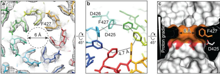
In the PA pore, the seven 2β10–2β11 loops of the heptamer converge to form an iris with a 6-Å hole bounded by a symmetric arrangement of the seven Phe427 residues (Fig. 4). By contrast, these loops in the PA prepore do not engage each other10,12, but circumscribe a
30-Å central hole with adjacent Phe427 residues spaced ~14 30-Å apart (Extended Data Fig. 5a). In the PA pore, each 2β10–2β11 loop is stabilized by close interactions with the 2β7–2β8 loop of the same protomer and the 2β10–2β11 loops of its two neighboring protomers. The hydrogen bonds between Asn399 and Ser428 and between Asn399 and Lys397' of an adjacent protomer form a chain of interactions, which give rise to a ring of loops at the iris inside the PA pore (Extended Data Fig. 5b). Consistently, Ser428 mutant abolished protein translocation, and the Lys397 or Asn399 mutation resulted in a dominant negative
effect23–25. In the PA homologues found in Clostridium species, Lys397 and Asp426 are
both replaced by uncharged Gln26, implying that this chain of interactions might be formed differently in these homologues.
Author Manuscript
Author Manuscript
Author Manuscript
The aryl plane of Phe427 from each protomer is parallel to the central axis of the PA pore. Neighboring Phe427 residues interact with each other by aromatic CH-π interaction in a tilted T-shaped configuration27 and possibly by hydrophobic interaction, thus forming the Φ-clamp (Fig. 4, Extended Data Fig. 5). The integrity of the Φ-Φ-clamp is required for catalysis of protein translocation, as mutation of even a single Phe427 residue of the Φ-clamp severely reduced translocation efficiency and disrupted the seal against cation passage5. Because the PA pore translocates polypeptides with various side chains, the Φ-clamp may act like an elastic "O-ring" changing its size and shape to allow an unhindered passage of different amino acid residues while maintaining a good seal during translocation. In the recently reported structure of bacterial amyloid secretion channel CsgG, eight Phe residues form a Φ-clamp, which differs from that in the PA pore in having a 9.5-Å hole and facilitating protein translocation in an ungated manner28.
Evidence from electrophysiological studies indicates that the proton gradient across the endosomal membrane is the primary driving force for unidirectional translocation of proteins through the PA pore3. Proton-driven transporters usually involve protonation-dependent conformational changes of two or more alternating gates. In the PA pore, however, there is only one gate, i.e. the Φ-clamp, and neither the Φ-clamp nor its nearby residues likely undergo a protonation-dependent conformational change. Indeed, the PA pore structure supports the charge-state dependent Brownian ratchet model2–9, proposed
earlier. In this model a negative electrostatic barrier within the pore hinders the passage, by Brownian motion, of deprotonated acidic residues3,4,29. The fact that acidic residues in the
acidic environment of the endosome have a higher probability of being protonated, and thus free to pass the barrier, than ones in the neutral environment of the cytosol, leads necessarily to unidirectional movement of polypeptides across the barrier. Consistent with this model, the PA pore structure shows three acidic residues, Asp425, Asp426 and Glu398, to be near the Φ-clamp and proximal to the pore axis (Fig. 3b), generating a strong negative
electrostatic barrier demarkating the endosomal and cytosolic compartments. In addition, the highly conserved acidic residue Asp425 located directly underneath the Φ-clamp is ideally positioned as a proton sink that may strip off protons from protonated acidic residues passing the Φ-clamp (Fig. 4c). Besides the charge barrier in the Φ-clamp, efficient protein translocation may require additional charged spots, such as the top region of the β barrel8.
A key question regarding the low-pH triggered conversion from prepore to pore is how PA senses pH. A notable conformational change during the conversion is that the 2β10–2β11 loop is flipped from one side to the other (Fig. 5a, Extended Data Fig. 6). Interestingly, this loop has different conformations in the two crystal structures of PA octameric prepores ([PA63]8, PDB ID: 3HVD; [PA63]8[LFN]4, PDB ID: 3KWV) whereas the remaining parts of the structures are largely unchanged9,13,14; i.e., this loop is in the pore and prepore states in
3HVD (Extended Data Fig. 6b) and 3KWV, respectively. This comparison suggests that the 2β10–2β11 loop can switch between two conformations without affecting the overall
structure. Mutation of the conserved Asn422 or Asp425 in this loop abolished the prepore to pore conversion at low pH in a dominant negative manner25. Therefore we interpret this loop as a pH sensor. Surprisingly, this loop does not possess any His, a residue whose pKa of ~6 falls in the pH range of 5–7 where the prepore to pore conversion occurs. The
Author Manuscript
Author Manuscript
Author Manuscript
conformational change of this loop might result from destabilization and rearrangement of hydrogen bonds upon exposure to low pH, or alternatively from perturbed pKa of Asp residues (425 and 426) in this loop. We note that other parts of PA might impact pH sensing. Prior work has shown mutation of residues near or in the 2β2–2β3 loop, or at the domain 2/
domain 4 interface, or deletion of the 2β2–2β3 loop changed the pH threshold for conversion
but did not abolish the low-pH sensitivity25,30. These observations suggest that the involved residues might regulate pH sensing.
We find that the prepore to pore conversion involves three layers of conformational changes, all located within domain 2 (Fig. 5b). The first layer is the above-mentioned pH-sensing 2β10–2β11 loop. Low-pH triggered conformational change of this loop is relayed to the
following layers sequentially as detailed below.
The second layer involves the 2β7–2β8, 2β5–2β6, and 2β12–2β13 loops, which are positioned
in an anti-parallel manner (Fig. 5a). In the PA pore, the N-terminal half of the 2β7–2β8 loop
moves downward to form a U-shaped turn tethered to the putative pH-sensing 2β10–2β11
loop via a hydrogen bond between Asn399 and Ser428 (Fig. 5a, Extended Data Fig. 5b, 6e). This new inter-loop interaction may relay the low-pH triggered conformational changes from the first layer to the second layer as supported by the dominant negative effect of Asn399 or Lys397 mutant24,25, which breaks the hydrogen bond network connecting these two loops (Extended Data Fig. 5b). As a result of the downward pull from the 2β7–2β8 loop,
all three loops of the second layer become straightened in the PA pore, with parts of the 2β5–
2β6 and 2β12–2β13 loops forming strands to augment 2β6 and 2β12, respectively (Fig. 5a,
Extended Data Fig. 6c, f). This conformational change is supported by the observation that mutating any of Pro379, Val455, and Asn458 of these loops led to defects in protein translocation25. This conformational change leads to the convergence of domains 2c and formation of the Φ-clamp by a 15° rotation of domain 2c around the hinge residues Ile261 and Tyr456, with its distal edge moving for 12 Å towards the central axis of the PA pore (Fig. 5c, Supplementary Video 2). Indeed, tethering domain 2 to domain 4 by receptor binding or stabilizing the interface between these two domains by a poly-γ-D-glutamate capsule impeded domain convergence and therefore decreased the pH threshold required for the prepore to pore conversion11,12,30. Conversely, destabilizing the domain 2/domain 4 interface by point mutations increased the pH threshold30.
The third layer, resulting from the second layer of conformational changes, involves release and refolding of the precursor of domain 2s (i.e., 2β2, 2β3, 2α1 and the membrane insertion
loop), and leads to the formation of the membrane-spanning β barrel (Fig. 2, Fig. 5b, Extended Data Fig. 7). The rotation of domains 2c opens the pocket between domains 2c and 4 to release the precursors of domains 2s, which then come together to form the β barrel (see details in Extended Data Fig. 7b). The β barrel formation might be the result, rather than the cause, of the convergence of domains 2c, as supported by a cryoEM map obtained from a subset of particles that shows converged domain 2c in the pore state but lacks the β barrel (Extended Data Fig. 8). We note that the stability of the domain 2/domain 4 interface was found to be a rate-limiting barrier to the conversion30 and the separation between domains
2c and 4 might also happen at an earlier stage of the conversion.
Author Manuscript
Author Manuscript
Author Manuscript
Taken together, these results suggest a multi-step mechanistic model of the low-pH triggered conversion from prepore to pore (Fig. 5d). First, the 2β10–2β11 loop as a pH sensor changes
its conformation upon acidification (layer 1). Second, as a consequence, the 2β7–2β8, 2β5–
2β6, and 2β12–2β13 loops become ordered (layer 2), resulting in the convergence of domains
2c and the formation of the Φ-clamp. Last, as a result of the separation of domain 2c from domain 4, the precursors of domains 2s are released and refold into a uniform β barrel (layer 3), which, as a final step, inserts into the endosomal membrane, ready for delivering the toxic enzymes into the cytosol.
In the PA pore, the convergence of domains 2c creates a large inter-protomer interface to stabilize the pore conformation (Extended Fig. 7a). Key to the formation of a functional PA pore is a newly identified interface between the 2β9–2β10 loop of one protomer and the
triple-stranded β sheet (2β12, 2β6, and 2β7) of its neighbor (Fig. 5e). The above-mentioned
convergence of domains 2c brings them together to form a new binding interface primarily mediated by hydrogen bonds between the backbone of the loop and the side chains of Thr390, Thr393, and Asp451 of the β sheet (Fig. 5e). These interactions explain the dominant negative effect of Ser382 or Thr393 mutant, the loss of PA activity of the Cys mutant of Thr390 or Asp451, and the conservation of Thr390 and Thr393 in PA
homologues25. By contrast, these residues are accessible and free of interactions in the PA prepore, and thus might be potential drug targets for blocking the conversion to functional PA pores.
In summary, the 2.9-Å structure of anthrax PA pore suggests the 2β10–2β11 loop as a pH
sensor to trigger conformational changes for prepore to pore conversion, supports a charge-state dependent Brownian ratchet model of proton-driven protein translocation, and can inform both efforts to engineer PA to target cancer cells and to design measures to block anthrax toxin entering cells14,21. A more detailed mechanism of protein translocation through the PA pore awaits additional experimental evidence, such as structures of the PA pore in the act of polypeptide translocation.
METHODS
Preparation of PA prepores
PA63 prepores were prepared following the described procedures31. EM sample preparation and data acquisition
For negative-stain EM, 2 µl of 0.1% polylysine solution (Polysciences) was first applied to a glow-discharged grid covered with carbon film and then removed by blotting with filter paper in 2 min. The polylysine treatment produced different orientations of particles on EM grids32, therefore overcoming the problem of preferred orientation for the PA pore.
Immediately after removal of polylysine, 2 µl of PA prepore (~50 µg/ml) was applied to the grid and incubated for 1 min. The grid was then washed with the high pH buffer (50 mM HEPES, 50 mM NaCl, pH 8.0) twice followed by two washes with the low pH buffer (50 mM NaOAc, pH 5.0, 0.05% Igepal CA-630) to induce the conversion of prepore to pore. After removal of excess buffer, the grid was stained with 0.8% (w/v) uranyl formate.
Author Manuscript
Author Manuscript
Author Manuscript
For cryoEM, Quantifoil R1.2/1.3 holey grids were covered with a thin layer of continuous carbon film a day before use. The procedure for pore induction on cryoEM grids was carried out following the same procedure for the negative-stain EM except that the last step of staining was not used. About 1.5 µl of low pH buffer was left on the grids before they were transferred into an FEI Vitrobot Mark IV. The grids were then blotted and flash-frozen in liquid ethane in the Vitrobot at 100% humidity. The frozen grids were stored in liquid nitrogen before use.
Negative-stain EM micrographs were acquired with Leginon automation software33,34 and a TIETZ F415MP 16-megapixel CCD camera at 68,027× magnification in an FEI Tecnai F20 electron microscope operated at 200 kV. The micrographs were saved by 2× binning to yield a pixel size of 4.4 Å.
Frozen-hydrated cryoEM grids were loaded into an FEI Titan Krios electron microscope operated at 300 kV for automated image acquisition with Leginon. CryoEM micrographs were recorded on a Gatan K2 Summit direct electron detection camera using the electron counting mode at 22,500 × nominal magnification (calibrated pixel size of 1.28 Å on the sample level) and defocus values ranging from −1.8 to −5.1 µm. The dose rate on the camera was set to ~8 e−/pixel/s. The total exposure time was 8 s and fractionated into 32 frames of subimages with 0.25 s exposure time for each frame. Frame images were aligned and averaged for correction of beam-induced drift using the GPU-accelerated program from Yifan Cheng's lab35. The average images from all frames were used for defocus
determination and particle picking, and those from the first 16 frames (corresponding to ~20 e−/Å2 total dose on sample) were used for 2D and 3D image classification. In total, 12,416 micrographs were taken in a continuous session. The best 7,062 micrographs were selected for the following in-depth data processing.
Image processing
For negative-stain EM single particle reconstruction, 140,775 particles were picked from 1,115 negative-stain EM micrographs using the batchboxer program of EMAN36. Particles were windowed out in 96×96 pixels. The defocus value of each micrograph was determined by CTFFIND37 and particles were corrected for contrast transfer function (CTF) by phase-flipping with the corresponding defocus and astigmatism values using Bsoft38. An initial model was generated using the startcsym program of EMAN. The refinement was then performed with 7-fold symmetry using EMAN.
For cryoEM single particle reconstruction, 21,200 particles (256×256 pixels) were initially picked by hand from 1,928 micrographs and subjected to auto-refinement by RELION39,40 using the negative-stain EM map obtained above as the initial model. The resulting cryoEM map (~4 Å resolution) was used to generate projections that were then served as templates to pick 259,719 particles from all of the 7,062 micrographs using the batchboxer of EMAN. In our procedure, the defocus values of the micrographs were determined by CTFFIND and particles were corrected for CTF by phase-flipping using Bsoft. The particles were processed with 2D and 3D classifications using the recommended procedures of RELION (http:// www2.mrc-lmb.cam.ac.uk/relion/index.php/Recommended_procedures). 2D class averages and 3D class reconstructions were inspected and those without high-resolution and
Author Manuscript
Author Manuscript
Author Manuscript
interpretable features were considered as "bad" classes. Particles contributing to the bad classes were discarded. The remaining 60,455 particles were selected for the final structure refinement. The C7 symmetry was applied throughout the 3D classification and 3D auto-refinement.
To maximize usable signals from the frame images acquired with the K2 Summit camera, we employed the resolution and dose-dependent model of radiation damage recently introduced in RELION-1.3 in the following steps41. First, the particle images averaged from all 32 frames with whole-image drift correction were used for a preliminary 3D auto-refinement. Second, particle images from individual frames were used to calculate translational alignments for the particle-based drift correction. A running average of seven frames, a standard deviation of one pixel, and fitting of linear tracks through the translations for all running averages were used for the optimal translational alignment following the suggested protocol of RELION. Last, particle images from frame 3 to frame 27 (~30 e−/Å2
total dose on sample) were translated using the above optimal alignment and weighted with different B-factors as estimated from the single-frame reconstructions to generate optimal "shiny" average images. Application of this procedure to the above selected particles yielded 60,455 "shiny" particles.
These "shiny" particles were then subjected to 3D auto-refinement in RELION to generate the final cryoEM map. RELION post-processing with a soft auto-mask42 estimated a resolution of 2.9 Å by the gold-standard FSC at 0.143 criterion and a B-factor of −95 Å2, and the post-processing without any mask reported a resolution of 3.3 Å. The accuracies of rotation and translation reported by RELION 3D auto-refinement were 1.67° and 1.01 Å. For visualization and atomic model building, the cryoEM map was sharpened and low-pass filtered by RELION post-processing using the above-mentioned B-factor and resolution. Local resolution was calculated by ResMap43 using the two cryoEM maps independently refined from halves of data.
3D classification and auto-refinement also identified a subset of 21,632 particles that led to a cryoEM map at 3.6 Å resolution which is in the pore state but lacks the density
corresponding to the 14-stranded β barrel, i.e. only has the corolla and calyx of the PA pore.
Atomic model building and refinement
De novo atomic model building of the PA pore except its domain 4 was carried out on the
cryoEM map at 2.9 Å resolution using Coot44. The coarse model was then refined using
PHENIX in a psudo-crystallographic manner45. Note this procedure only improved the atomic model and did not modify the cryoEM map. Briefly, the cryoEM map was put into an artificial crystal lattice to calculate its structure factor using the em_map_to_hkl.inp utility program in CNS46. The amplitudes and phases of the structural factor were used as pseudo-experimental diffraction data for model refinement in PHENIX. The restraints of Ramachandran, secondary structure, and non-crystallographic symmetry were used in the refinement.
The cryoEM maps and atomic models were visualized using UCSF Chimera47 or PyMOL48. The available crystal structures of PA83 monomer (e.g. PDB ID: 1ACC and 3TEW) and
Author Manuscript
Author Manuscript
Author Manuscript
PA63 heptameric prepore (PDB ID: 1TZO) are highly similar to each other, therefore
3TEW, which has the highest resolution among them, was used for structural comparison with our cryoEM structure of PA pore in most situations and 1TZO was used when the inter-protomer interaction or domain movement were considered.
Extended Data
Extended Data Figure 1. Negative-stain and cryoEM of the PA pore
Author Manuscript
Author Manuscript
Author Manuscript
a, Negative-stain EM micrograph of PA pore particles. Some representative top-view and
side-view particles are selected with circles and squares, respectively. b, A full-size drift-corrected cryoEM micrograph of 3710 × 3710 pixels of PA pore particles acquired from a Gatan K2 Summit direct electron detection camera, and at 300 kV accelerating voltage, −2.7 µm defocus, and a total dose of 39 e−/Å2. Some representative side-view particles of PA pore are indicated by arrows. c, Powerspectrum of the cryoEM micrograph in (b). d, Representative cryoEM 2D class averages of particles at different orientations. e–h,
Superimposition of representative regions of the cryoEM map (mesh) with the atomic model (stick), including α helix (e), β strand (f), loop (g), and Ca2+ ions (green spheres in h).
Extended Data Figure 2. Resolution estimation of the cryoEM single particle reconstruction of the PA pore
a, “Gold-standard” Fourier shell correlation (FSC) between two independently refined maps
with an auto-mask that was corrected by phase randomization. The resolution was estimated by the gold-standard FSC at 0.143 criterion42. b, FSC of the final atomic model versus the final cryoEM map (black); of a model refined in the first of the two independent maps used for the gold-standard FSC versus the same map (red) and versus the second independent map (blue). c, Surface view and cut-through view of the unsharpened cryoEM map colored
Author Manuscript
Author Manuscript
Author Manuscript
by local resolution estimated by ResMap43. d, Euler angle distribution of all particles used for the final 3D reconstruction.
Extended Data Figure 3. Fitting of domain 4 into the cryoEM map of PA pore
a, The crystal structure of domain 4 (purple ribbons) from PA prepore (PDB ID: 1TZO) fits
the cryoEM map (grey surface) of PA pore with a good agreement (cross-correlation coefficient: 0.91). b, Translocation of domain 4 during the prepore to pore conversion. Domain 4 is shifted inwards as a rigid-body for 4 Å from the prepore conformation (dark cyan) to the pore conformation (purple).
Extended Data Figure 4. Comparison of the structures of the PA pore, α-hemolysin (PDB ID: 7AHL), and Vibrio cholerae cytolysin (PDB ID: 3O44)
Author Manuscript
Author Manuscript
Author Manuscript
These three complexes are in their membrane-inserted forms. The approximate position of the lipid bilayer is illustrated with grey shade. The host cell receptor (TEM8 or CMG2) of PA that binds to domain 4 (grey ribbons) is schematically illustrated.
Extended Data Figure 5. Assembling of the Φ-clamp in the PA pore
a, Comparison of the Φ-clamp in the PA pore with its corresponding region in the PA
prepore. The residues Asp426 and Phe427 missing in the crystal structure of the PA63
prepore (PDB ID: 1TZO) are modeled based the crystal structure of the PA83 monomer
Author Manuscript
Author Manuscript
Author Manuscript
(PDB ID: 1ACC). b, Close-up top view of the Φ-clamp region in the PA pore. The 2β7–2β8
and 2β10–2β11 loops are colored in cyan and orange, respectively. The hydrogen bonds
between Ser428, Asn399, and Lys397’, which form a chain tethering the 2β7–2β8 and 2β10–
2β11 loops together, are depicted with dashed lines.
Extended Data Figure 6. Conformational changes of domain 2c between the PA prepore and the PA pore
a, Superimposition of domains 2c of the PA pore and the crystal structure of the PA
heptameric prepore (PDB ID: 1TZO). The dashed boxes highlight the conformational
Author Manuscript
Author Manuscript
Author Manuscript
difference of the 2β10–2β11 loop between these two structures. Residues Asp426 and Phe427
are not solved in the crystal structure of PA prepore due to their flexibility. b,
Superimposition of domains 2c of the PA pore and the PA octameric prepore (PDB ID: 3HVD). Note the similarity of the 2β10–2β11 loop (dashed box) between these two
structures. c, Superimposition of domains 2c of the PA pore and the PA prepore (monomer; PDB ID: 3TEW). d–f, Close-up views of the rearrangements of the 2β10–2β11 loop (d), the
2β7–2β8 loop (e), and the 2β5–2β6 and 2β12–2β13 loops (f) during the conversion from prepore to pore. Val377 and Leu378 of the 2β5–2β6 loop and Val455 and Tyr456 of the 2β12–2β13 loop are flipped upside down to obtain the β strand conformation in the PA pore, leading to an extension of 2β6 and 2β12 (f). CryoEM densities (mesh) corresponding to these
loops are displayed to the right of d–f with atomic models superimposed, showing unambiguous atomic modeling. The superimpositions of the cryoEM map and the atomic model are shown in views different from the left panels for clarity. The conformational changes of these loops result in a more compact domain 2c with a decrease of 567 Å2 in its surface area.
Extended Data Figure 7. Compact assembly of the PA pore
Author Manuscript
Author Manuscript
Author Manuscript
a, Surface views of two neighboring protomers (the same domains in the two protomors are
in different shades of the same colors) of the PA pore and the PA prepore (PDB ID: 1TZO) visualized from inside PA heptamer. Domains 1', 2c, 2s, and 3 are colored differently and domain 4 is not shown. The inter-protomer interface in the PA prepore is largely formed by domains 1' and 3 and domain 2 only contributes to this interface by its membrane insertion loop and C-terminal region (2β13, 2β14, and 2α3). In the PA pore, the convergence of
domain 2c creates an inter-protomer interface without any gap, with an increase of interface area on domain 2c from 1,247 Å2 of the PA prepore to 2,106 Å2 of the PA pore as
calculated using the PISA49 (http://www.ebi.ac.uk/pdbe/pisa/). Additionally, formation of the β barrel also leads to extensive contacts, creating a new interface area of 1,195 Å2 between two protomers. b, Schematic of the conversion of 2β2, 2β3, 2α1, and the membrane
insertion loop of the PA prepore to 2β2s and 2β3s of the PA pore. Hydrogen bonds between
2β2 and 2β3, which are depicted with dashed lines, are maintained during the conversion. By
contrast, 2α1 and the connecting loops have to be fully unfolded and converted into β strands
that collectively assemble the β barrel of the PA pore. Although the detailed events of β barrel formation are not yet clear, it is likely that assembly starts from the top in a zipper-like manner. A favorable scenario is that the convergence of domains 2c would place the top ends of the β strands close to each other to form a short β barrel, which could extend by pulling more residues together via formation of ordered hydrogen bonds until it reaches the bottom end. It is less favorable that the assembly starts from other regions because
disordered hydrogen bonds and hydrophobic interactions could generate enormous non-productive, possibly irreversible pairings between strands.
Author Manuscript
Author Manuscript
Author Manuscript
Extended Data Figure 8. CryoEM single particle reconstruction of a subset of particles lacking the 14-stranded β barrel
a, Surface views of the cryoEM map lacking the β barrel. The map is unsharpened and has a
resolution of 3.6 Å. b, Cross-section side view of superimposition of the unsharpened cryoEM map with the atomic model of the intact PA pore, showing the cryoEM map has the same conformation as the PA pore except for the absence of the 14-stranded β barrel. c, “Gold-standard” FSC (with an auto-mask that was corrected by phase randomization) between two independently refined maps. d, Top view of the Φ-clamp region of the cryoEM map (mesh) lacking the β barrel superimposed with the atomic model of the PA pore (ribbons), showing correct assembling of the Φ-clamp in the cryoEM map.
Extended Data Table 1
Data collection and structure refinement statistics. Data Collection Particles 60,455 Pixel size (Å) 1.28 Defocus range (µm) −1.8 to −5.1 Voltage (kV) 300
Author Manuscript
Author Manuscript
Author Manuscript
Author Manuscript
Total electron dose 39 e−/Å2 Electron dose used in the final reconstruction 30 e−/Å2 Refinement
Resolution (Å) 2.9
Map sharpening B-factor (Å2) −95
Average B-factor (Å2) 81
R.m.s deviations
Bond lengths (Å2) 0.009
Bond angles (°) 1.083
Supplementary Material
Refer to Web version on PubMed Central for supplementary material.
Acknowledgements
This work was supported in part by grants from the National Institutes of Health (AI046420/AI094386 and GM071940 to Z.H.Z) and the American Heart Association (Postdoctoral Fellowship 14POST18870059 to J.J.). We acknowledge the use of instruments at the Electron Imaging Center for Nanomachines supported by UCLA and by instrumentation grants from NIH (1S10RR23057, 1S10OD018111) and NSF (DBI-1338135). We thank Lei Jin for initial efforts of this project and Juli Feigon for helpful discussion.
REFERENCES
1. Young JA, Collier RJ. Anthrax toxin: receptor binding, internalization, pore formation, and translocation. Annu. Rev. Biochem. 2007; 76:243–265. [PubMed: 17335404]
2. Krantz BA, et al. A phenylalanine clamp catalyzes protein translocation through the anthrax toxin pore. Science. 2005; 309:777–781. [PubMed: 16051798]
3. Krantz BA, Finkelstein A, Collier RJ. Protein translocation through the anthrax toxin
transmembrane pore is driven by a proton gradient. J. Mol. Biol. 2006; 355:968–979. [PubMed: 16343527]
4. Basilio D, Juris SJ, Collier RJ, Finkelstein A. Evidence for a proton-protein symport mechanism in the anthrax toxin channel. J. Gen. Physiol. 2009; 133:307–314. [PubMed: 19204186]
5. Janowiak BE, Fischer A, Collier RJ. Effects of introducing a single charged residue into the phenylalanine clamp of multimeric anthrax protective antigen. J. Biol. Chem. 2010; 285:8130– 8137. [PubMed: 20061382]
6. Basilio D, Jennings-Antipov LD, Jakes KS, Finkelstein A. Trapping a translocating protein within the anthrax toxin channel: implications for the secondary structure of permeating proteins. J. Gen. Physiol. 2011; 137:343–356. [PubMed: 21402886]
7. Brown MJ, Thoren KL, Krantz BA. Charge requirements for proton gradient-driven translocation of anthrax toxin. J. Biol. Chem. 2011; 286:23189–23199. [PubMed: 21507946]
8. Wynia-Smith SL, Brown MJ, Chirichella G, Kemalyan G, Krantz BA. Electrostatic ratchet in the protective antigen channel promotes anthrax toxin translocation. J. Biol. Chem. 2012; 287:43753– 43764. [PubMed: 23115233]
9. Feld GK, Brown MJ, Krantz BA. Ratcheting up protein translocation with anthrax toxin. Protein Sci. 2012; 21:606–624. [PubMed: 22374876]
10. Petosa C, Collier RJ, Klimpel KR, Leppla SH, Liddington RC. Crystal structure of the anthrax toxin protective antigen. Nature. 1997; 385:833–838. [PubMed: 9039918]
11. Santelli E, Bankston LA, Leppla SH, Liddington RC. Crystal structure of a complex between anthrax toxin and its host cell receptor. Nature. 2004; 430:905–908. [PubMed: 15243628]
Author Manuscript
Author Manuscript
Author Manuscript
12. Lacy DB, Wigelsworth DJ, Melnyk RA, Harrison SC, Collier RJ. Structure of heptameric protective antigen bound to an anthrax toxin receptor: a role for receptor in pH-dependent pore formation. Proc. Natl. Acad. Sci. U. S. A. 2004; 101:13147–13151. [PubMed: 15326297] 13. Kintzer AF, et al. The protective antigen component of anthrax toxin forms functional octameric
complexes. J. Mol. Biol. 2009; 392:614–629. [PubMed: 19627991]
14. Feld GK, et al. Structural basis for the unfolding of anthrax lethal factor by protective antigen oligomers. Nat. Struct. Mol. Biol. 2010; 17:1383–1390. [PubMed: 21037566]
15. Vernier G, et al. Solubilization and characterization of the anthrax toxin pore in detergent micelles. Protein Sci. 2009; 18:1882–1895. [PubMed: 19609933]
16. Sehnal D, et al. MOLE 2.0: advanced approach for analysis of biomacromolecular channels. J Cheminform. 2013; 5:39. [PubMed: 23953065]
17. Ziv G, Haran G, Thirumalai D. Ribosome exit tunnel can entropically stabilize alpha-helices. Proc. Natl. Acad. Sci. U. S. A. 2005; 102:18956–18961. [PubMed: 16357202]
18. Voss NR, Gerstein M, Steitz TA, Moore PB. The geometry of the ribosomal polypeptide exit tunnel. J. Mol. Biol. 2006; 360:893–906. [PubMed: 16784753]
19. Killian JA, von Heijne G. How proteins adapt to a membrane-water interface. Trends Biochem. Sci. 2000; 25:429–434. [PubMed: 10973056]
20. Wang J, Vernier G, Fischer A, Collier RJ. Functions of phenylalanine residues within the beta-barrel stem of the anthrax toxin pore. PLoS One. 2009; 4:e6280. [PubMed: 19609431] 21. Song L, et al. Structure of staphylococcal alpha-hemolysin, a heptameric transmembrane pore.
Science. 1996; 274:1859–1866. [PubMed: 8943190]
22. De S, Olson R. Crystal structure of the Vibrio cholerae cytolysin heptamer reveals common features among disparate pore-forming toxins. Proc. Natl. Acad. Sci. U. S. A. 2011; 108:7385– 7390. [PubMed: 21502531]
23. Sellman BR, Nassi S, Collier RJ. Point mutations in anthrax protective antigen that block translocation. J. Biol. Chem. 2001; 276:8371–8376. [PubMed: 11113126]
24. Sellman BR, Mourez M, Collier RJ. Dominant-negative mutants of a toxin subunit: an approach to therapy of anthrax. Science. 2001; 292:695–697. [PubMed: 11326092]
25. Mourez M, et al. Mapping dominant-negative mutations of anthrax protective antigen by scanning mutagenesis. Proc. Natl. Acad. Sci. U. S. A. 2003; 100:13803–13808. [PubMed: 14623961] 26. Melnyk RA, Collier RJ. A loop network within the anthrax toxin pore positions the phenylalanine
clamp in an active conformation. Proc. Natl. Acad. Sci. U. S. A. 2006; 103:9802–9807. [PubMed: 16785422]
27. Ballester, P.; Biros, SM. The Importance of Pi-Interactions in Crystal Engineering. John Wiley & Sons, Ltd; 2012. p. 79-107.
28. Goyal P, et al. Structural and mechanistic insights into the bacterial amyloid secretion channel CsgG. Nature. 2014; 516:250–253. [PubMed: 25219853]
29. Finkelstein A. Proton-coupled protein transport through the anthrax toxin channel. Philos. Trans. R. Soc. Lond. B Biol. Sci. 2009; 364:209–215. [PubMed: 18957378]
30. Kintzer AF, Tang II, Schawel AK, Brown MJ, Krantz BA. Anthrax toxin protective antigen integrates poly-gamma-D-glutamate and pH signals to sense the optimal environment for channel formation. Proc. Natl. Acad. Sci. U. S. A. 2012; 109:18378–18383. [PubMed: 23100533]
EXTENDED DATA REFERENCES
31. Wigelsworth DJ, et al. Binding stoichiometry and kinetics of the interaction of a human anthrax toxin receptor, CMG2, with protective antigen. J. Biol. Chem. 2004; 279:23349–23356. [PubMed: 15044490]
32. Ortega J, Singh SK, Ishikawa T, Maurizi MR, Steven AC. Visualization of substrate binding and translocation by the ATP-dependent protease, ClpXP. Mol. Cell. 2000; 6:1515–1521. [PubMed: 11163224]
33. Suloway C, et al. Automated molecular microscopy: The new Leginon system. Journal of Structural Biology. 2005; 151:41–60. [PubMed: 15890530]
Author Manuscript
Author Manuscript
Author Manuscript
34. Suloway C, et al. Fully automated, sequential tilt-series acquisition with Leginon. Journal of Structural Biology. 2009; 167:11–18. [PubMed: 19361558]
35. Li X, et al. Electron counting and beam-induced motion correction enable near-atomic-resolution single-particle cryo-EM. Nat. Methods. 2013; 10:584–590. [PubMed: 23644547]
36. Ludtke SJ, Baldwin PR, Chiu W. EMAN: Semiautomated software for high-resolution single-particle reconstructions. Journal of Structural Biology. 1999; 128:82–97. [PubMed: 10600563] 37. Mindell JA, Grigorieff N. Accurate determination of local defocus and specimen tilt in electron
microscopy. Journal of Structural Biology. 2003; 142:334–347. [PubMed: 12781660]
38. Heymann JB. Bsoft: Image and molecular processing in electron microscopy. Journal of Structural Biology. 2001; 133:156–169. [PubMed: 11472087]
39. Scheres SH. RELION: implementation of a Bayesian approach to cryo-EM structure determination. J. Struct. Biol. 2012; 180:519–530. [PubMed: 23000701]
40. Scheres SH. A Bayesian view on cryo-EM structure determination. J. Mol. Biol. 2012; 415:406– 418. [PubMed: 22100448]
41. Scheres SH. Beam-induced motion correction for sub-megadalton cryo-EM particles. Elife. 2014; 3:e03665. [PubMed: 25122622]
42. Amunts A, et al. Structure of the yeast mitochondrial large ribosomal subunit. Science. 2014; 343:1485–1489. [PubMed: 24675956]
43. Swint-Kruse L, Brown CS. Resmap: automated representation of macromolecular interfaces as two-dimensional networks. Bioinformatics. 2005; 21:3327–3328. [PubMed: 15914544]
44. Emsley P, Cowtan K. Coot: model-building tools for molecular graphics. Acta Crystallogr. D Biol. Crystallogr. 2004; 60:2126–2132. [PubMed: 15572765]
45. Adams PD, et al. PHENIX: a comprehensive Python-based system for macromolecular structure solution. Acta Crystallogr. D Biol. Crystallogr. 2010; 66:213–221. [PubMed: 20124702] 46. Brunger AT, et al. Crystallography & NMR system: A new software suite for macromolecular
structure determination. Acta Crystallogr. D Biol. Crystallogr. 1998; 54:905–921. [PubMed: 9757107]
47. Pettersen EF, et al. UCSF Chimera—A visualization system for exploratory research and analysis. Journal of Computational Chemistry. 2004; 25:1605–1612. [PubMed: 15264254]
48. Schrodinger, LLC. The PyMOL Molecular Graphics System, Version 1.7.2. 2014.
49. Krissinel E, Henrick K. Inference of macromolecular assemblies from crystalline state. J. Mol. Biol. 2007; 372:774–797. [PubMed: 17681537]
Author Manuscript
Author Manuscript
Author Manuscript
Figure 1. CryoEM reconstruction of the PA pore
a, b, Surface representations of the cryoEM map of the PA pore at 2.9 Å resolution as
viewed from the top (a) and the side (b). Individual protomers of PA heptamer are color-coded. Inset of (b) shows the unsharpened cryoEM map in which the flexible domains 4 (arrowheads) are visible.
Author Manuscript
Author Manuscript
Author Manuscript
Figure 2. Atomic model of the PA pore
a, Top and side views of the atomic model of the PA pore shown as ribbons. Protomers are
color-coded except for domain 4 (grey). b, Structural comparison of the protomers of the PA pore and prepore (PDB ID: 1TZO). The domains are colored differently according to c. c, domain organization of the PA protomer.
Author Manuscript
Author Manuscript
Author Manuscript
Figure 3. Translocation channel of the PA pore
a, Electrostatic surface (left) and channel radius profile (right; calculated with MOLE16) of the PA pore. An α helix (green surface model of residues 555–574 of LF; PDB ID: 1J7N) is modeled in the β barrel. The green arrow depicts the direction of protein translocation. b, The translocation channel (dots) running through the Φ-clamp. Two protomers of the PA pore are shown as ribbons. Residues E398, D425, D426, F427, and S429 (ball-and-stick) are exposed to the channel. c, d, Hydropathy surface of the PA pore (brown: hydrophobic; purple: hydrophilic; white: neutral). In c, the front half of the structure is removed to show the luminal surface. In d, two 1,2-dihexadecanoyl-sn-glycero-3-phosphocholine (DPPC) lipid molecules are modeled near the membrane insertion region. e, Bottom and side views of the segmented cryoEM map showing the β barrel (yellow) bound with disordered detergent molecules (grey). f, The 14-stranded β barrel (ribbons) and the hydrophobic residues (spheres) on its outer surface. The hydrophobic residues are depicted on different protomers for the ease of presentation.
Author Manuscript
Author Manuscript
Author Manuscript
Figure 4. Structure of the Φ-clamp
a, Top view of the Φ-clamp region of the PA pore showing the cryoEM map (mesh)
superimposed with the atomic model (stick). b, Tilted view of the Φ-clamp with seven protomers colored differently, showing the aromatic CH-π interaction. c, Cross-section side view of the translocation channel near the Φ-clamp region. The Φ-clamp (Phe427) and the conserved acidic residue Asp425 are colored in orange and red, respectively.
Author Manuscript
Author Manuscript
Author Manuscript
Figure 5. Conversion from prepore to pore
a, Superimposition of domains 2c of the PA pore and prepore (monomer; PDB ID: 3TEW).
Loops undergoing dramatic conformational changes during the prepore to pore conversion are labeled (blue). b, Overview of the three layers of conformational changes during the conversion. The interaction between the 2β9–2β10 loop and the β sheet (blue box) is shown
in panel e. c, Superimposition of the PA pore (pink, orange, and blue; colored by domain) and prepore (light green; PDB ID: 1TZO). Domains 4 and 2s are removed for clarity. Between the two structures, domain 2c has a Cα rmsd=6.87 Å, whereas domains 1' and 3 remain unchanged with Cα rmsd=0.54 Å and 0.58 Å, respectively. d, Illustration of the steps of conformational changes during the prepore to pore conversion. For simplicity, only two protomers are illustrated. e, Interface between the 2β9–2β10 loop (green) and the bent β sheet
(gold) of 2β12, 2β6, and 2β7 of the adjacent protomer in the PA pore. Hydrogen bonds
between the backbone of the loop and the side chains of the β sheet are depicted with dashed lines.