oL
o
s^
D£V«-HD28
.M414
WORKING
PAPER
ALFRED
P.SLOAN
SCHOOL
OF
MANAGEMENT
Augmenting
theHouse
ofQuality with EngineeringModels
by
RajanRamaswamy
KarlUlrichWP
#3456-92August
1992MASSACHUSETTS
INSTITUTE
OF
TECHNOLOGY
50MEMORIAL
DRIVE
CAMBRIDGE,
MASSACHUSETTS
02139
Augmenting
theHouse
ofQuality with EngineeringModels
by
Rajan
Ramaswamy
Karl Ulrich
MASSACHIJSFTTSINSTITUTE
JAN
04
1996Augmenting
the
House
of
Quality
with
Engineering
Models
Raj
an
Ramaswamy
Karl
UlrichiMassachusetts
Institute ofTechnology
Abstract
To
develop successful products the "Voice ofthe Customer" must be explicitlyconsidered in the design process.
The
House of Quality is an increasingly popular structured methodology for ensuring customer focus. In this paper, we describepreliminary work on augmenting the House ofQuality through the use of
engineer-ing models of product performance. Using an example drawn from practice, we
discuss practical problems with using the House of Quality and show
how
infor-mation from engineering models can be used to solve some of these problems.
We
identify some of the potential benefits ofthis approach and show
how
engineeringmodels and the information contained in the House of Quality can be unified in a
single representation.
Keywords:
House of Quality, modeling, design, product development, represen-tation^Direct all correspondence to this author at
MIT
Rm
E53-390, CambridgeMA
02139, (617)253-0487 ulncki§at. mti.edu.1
Introduction
The
degree to which a product satisfies customer desires is a critical product successfactor
[HOPM90, HOMP89].
A
consensus is rapidly developing in industrial practice that customer desires can only be obtained from actual contact with the customer andthat designers are often
wrong
when
they try to guesswhat
the customer wants [GR\V86,RMS3,
Ran89, SC78, UH80].To
facilitate customer focus, severalstructuredmethodolo-gies for organizing and presenting customer information have been developed.
One
suchmethodology
is theHouse
of Quality(HOQ),
which helps product designers to identify explicitly customer requirements, relatethem
to objective engineering characteristics,identify tradeoffs, and to evaluate the characteristics of a potential product relative to
competing products [CH88].
The
HOQ
is most often used to set targets for the engineering performance of aprod-uct. In a typical situation, marketing staff collect data about customers and competing
products and, with
some
input from engineering, decide a set of performance targetswhich are then
communicated
to the designers. In this paperwe
address two weaknessesof this methodology,
1. Targets set on customer information alone are often unrealistic.
Hence
designerscannot achieve
them
and this results in time-consuming iterations until acompro-mise is reached.
2.
The
roof of theHOQ
alone cannot adequately capture the complex couplingbe-tween design variables.
Hence
the trade-offs thatmust
bemade
in the design are over-simplified or even ignored.We
believe that engineering models, if used in conjunction with theHOQ,
can helpaddress these problems.
Designers often have rehable engineering models which they can use to test the limits
of product performance
[RUKT91].
The
inputs to these models, the design variables, are the actual quantities that the designer can controland
the outputs are the important performance metrics of the product. Engineering models can therefore be a valuabletool for exploring design tradeoffs and product performance without building extensive
prototype hardware.
In this paper
we
show
how
by having access to engineering models and theHOQ
simultaneously, designers
may
more
rapidly and reliably produce designs that satisfy thecustomer. Specifically,
we
examine
shortcomings of theHOQ
which manifest themselveswhen
it is used in a real design project andshow
how
augmenting it with mathematicalmodels of product performance helps solve
some
of these problems.We
illustrate all ourarguments with an
example
derived from an ongoing project with an industrial sponsorto design a hand-held
power
tool.To
protect our sponsor's proprietary data,we
presentSwitch \
HEAT
SINK
MOTOR
BATTERY
PACK
^
TRANS-
MISSION
Output Shaft/
Figure 1: Tool Concept (schematic)
a drill, but shares almost all of the
same
design issues.The
general statement of the disguised design problem is,Develop a hand-held cordless drill for the professional market which will take
up
to10mm
bitsand
be superior to existing competing products.We
furtherassume
thatwe
are at a point in the development process wherewe
havechosen a basic tool concept.
A
schematic description of the tool concept isshown
inFigure 1.
We
willshow
how
some
fairly difficult decisionsmust
bemade
even for thissimple product
and
how
theHOQ
and an engineering model can help designerswhen
making
these decisions.1.1
Roadmap
We
first providesome
general background on theHOQ
and discuss the information storedin it for the cordless drill design example.
We
then point outsome
of the shortcomingsof the
HOQ
approach, whichwe
have noticed in the course of attempting to applyit. Subsequently
we
describe an engineering model of performance for the drill designexample and
show
how
references to it can be used to correctsome
of the problemswith using the
HOQ.
The
idea of storing theHOQ
and performance models in a singlerepresentation to facihtate access and usage is then introduced.
We
conclude with asummary
of the key ideas and an outline of work planned for the future.2
Using
the
House
of
Quality
In this section,
we
describe theHOQ
and explain its use for the cordless drill. Readersfamiliar with the
HOQ
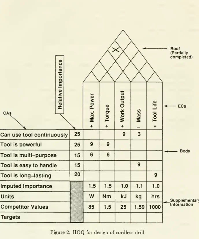
technique should skim the generic parts and concentrate onpor-tions related to the design example. Figure 2 contains important information about the
CAs
a>u
c
(0C
o
Q.E
>
ccCan
use
toolcontinuously
Tool
ispowerful
Tool
ismulti-purpose
Tool
iseasy
tohandle
Tool
islong-lasting
Imputed Importance
UnitsCompetitor Values
Targets
25
25
15
15
20
0)o
Q. •X
(0 1.5W
85
o
O
1.5Nm
1.53
a. "3o
o
+ 1.0kJ
25
(A 1.1kg
1.59o
o
o
1.0 hrs Roof (Partially completed)1000
ECs Body .Supplementary InformationThe
House
of Quality(HOQ)
is a tool for relating the consumers' desires {customerattributes in
HOQ
parlance) to technical performance specifications [engineeringcharac-teristicsin
HOQ
parlance).Customer
attributes collected through surveysand interviews are usually phrased in day-to-day language and are not suitable for direct use in an en-gineering project.The
important objective of theHOQ
technique is to help a productdevelopment
team
translate the customer attributes into formal engineering targets andto store the information necessary for this translation in a readable, understandable
for-mat.
The
HOQ
related to the design of a cordless drill is displayed in Figure 2. Itselements are:
•
Customer
Attributes (CAs):The
CAs
are usually actual statementsmade
bycus-tomers during interviews and surveys. For example in Figure 2,
"Can
use toolcontinuously"
and
"Tool is powerful" are quotes from actual customer statements.Note
alsothat theCAs
shown
are actually group headings that arosefromarrangingthe raw customer statements into related groups and then picking one statement
which was representative ofthe whole group. Estimates of the relative importance
ofthe
CAs
(a total of 100) are typically displayed in acolumn
adjacent to theCA
names
(see Figure 2).• Engineering Characteristics (ECs):
The
ECs
are the system-level technical productperformance characteristics that influence the customer attributes.
The
designermust
be able to assignECs
a numerical value and a unit. UsuallyECs
cannotbe fully identified until a basic product concept has been selected.
The
values inthe "body" of the
HOQ
(described next) and the relative importances of theCAs
can be used to impute importances to each
EC.
These values are stored as part of the supplementary information in theHOQ.
Further, a -|- or—
sign below eachEC
indicates if the designer wishes to maximize or minimize that value. In ourexample,
mass
is labelled with—
and max. poweris labelled with -f- because a toolwith low mass and high
power
is desirable.• "Body": This is a matrix, having rows labeled with the
CAs
and the columnsla-beled with the ECs,
whose
entries indicate the strength ofthe relationship betweenCAs
and
ECs. In other words each entry indicateshow
strongly the designer, bychanging the
EC,
can affect the aspect ofcustomer satisfaction represented by theCA.
Entries in thebody
may
be symbols ornumbers
indicating the strength of the relationship.We
usenumbers
on a scale from to 10 in our work (blank spaces inthe
body
in Figure 2 have value0). Figure2 shows, for example, that there are twoaspects to
making
the customers feel that they"Can
use tool continuously"-u'orfcoutput is the major factor (weight 9) and
mass
a comparatively minor one (weight3).
• "Roof":
The
roof helps recordhow ECs
interact with other ECs. Engineers oftenhave to "balance tradeoffs
when
addressing customer benefits" [CH88,GBW92]
and
hence it is useful to have answers to questions such as "Will lowering the masshave any effect on max. power?"
The
answers to such questions are stored in the "roof" of theHOQ,
once again in matrix form.An
entry corresponding to twoECs
indicates that the two are related. In one of the early papers on the subjectClausing and Hauser [CH88], use the symbols x and \/ to indicate "negative" and
"positive" relationships between ECs. For example. Figure 2 shows that
mass
and max.power
have a negative relationship, indicating that improving the toolpower
will worsen the tool mass. However,we
will shortly illustratewhy
such simplisticmeasures of coupling are inadequate in real design situations.
Supplementary Information:
The
portion of theHOQ
below thebody
is used tostore miscellaneous useful information such as target values for each
EC.
units.and values of that
EC
for competitors' products (forbenchmarking
purposes). .\particularly important row is the one giving the imputed importances for the ECs.
This is
computed
for eachEC
as the weightedsum
of the correlations withCAs
(the relative importance for each C.\ is the weight). These values are analogous
to the relative importances ofthe CAs.
They
help guide decisions which hinge ondeciding which
EC
to change so as to realize themaximum
possibleimprovement
in customer perception. Often the
HOQ
includes a region along the right side ofthe
body
toshow
the relative performance of each competitor's product for eachC.\. This is called a perceptual
map
in marketing jargon.We
have notshown
thisinformation in Figure 2.
Of
course, other relevant datamay
also be stored in thesupplementary area
and
in fact customization to suit individual design problems isencouraged.
3
Two
Problems
with
the
HOQ
Methodology
The
key benefits of theHOQ
methodology are that it helps designers answer twofunda-mental questions. These are (paraphrased from [CH88]).
•
How
can designers influence customer-perceived qualities andby
how
much?
•
How
does an engineering changeaffect other characteristics?Let us
examine
how
well theHOQ
helps the designer answer these two questions.The
HOQ
performs the important functionoftellingthe designershow
they currentlystand, i.e.
how
their product stacks up against competing products both in terms ofcustomer perception and engineering numbers. This information,
combined
with the correlation information from the body, can be used to set targets on the variousECs
which will enable the product to outstrip all the competitors.
When
attempting toachieve these targets the information in the roof is intended to ensure that no
EC
isimproved at the (unreasonable) expense of another.
• Setting targets is of no use unless these targets are realistically achievable. Using customer and competitor information alone to set targets willoftenresult in targets
that can never be achieved in practice.
ECs
cannot be set directly, they can onlybe indirectly controlled via the design variables for the problem.
•
The
natureofcoupHng
betweenECs
can bequitecomplexand
thiscannot be storedin the roof of the
HOQ
because of its extremely limited ability to accurately recordtradeoffs. In a typical design situation, two
ECs
will have severalcommon
design variables eind the behavior with respect to each of these variablesmay
be different.Hence
it is not possible to characterize the true tradeoff with just a single symbolrepresenting a positive or negative relationship.
\\'e beheve that these problems are best solved or at least alleviated through the
use of engineering models, which are mathematical models of product performance.
To
reinforce our assertion,
we
introducean engineeringmodel
for the drill example andshow
how
it can be used to solve the above problems.4
How
Do
Engineering
Models
Help?
Many
firms, manufacturing products rangingfrombearings to jet engines,havedevelopedengineering models for their products (for an example from the
domain
of automobiledesign, see [RUKT91]). These models are used to decide whether designs are feasible,
to explore the performance envelope of a design without actually building a physical
prototype, and to study the tradeoffs involved in the design. .-Xn engineering
model
is amathematical
model
that relates the design variables to the performance metrics used toquantify performance of a product. For example, the engineering
model
for the cordlessdrill relates design variables such as
number
of cells and motor choice to performancemetrics such as
maximum
power
and m.ass.The
structure of an engineeringmodel
for the cordless drillexample
isshown
inFigure 3.
The
variables (e.g. motor choiceand
transmission ratio)on
the extreme rightare the design variables for this problem and those on the extreme left (e.g. max. power
and mass) are the performance metrics.
Some
intermediate variables such as motortorque and overall efficiency are
computed
for convenience.The
structure of the networkin Figure 3 is such that ifvalues are specified for all the design variables, the performance
metrics can be
computed
fromthem
without iteration.As shown
in the figure causalityflows from right to left in the network.
Using an engineering
model
to calculate numerical values forthe performance metricsis only one use that it can be put to. Another major benefit is the insight it can offer
into the topology of the design problem.
Network
representations, such as the oneshown
in Figure 3.
make
it easier for the designer to understand which design variables affecta particular performance metric,
how
strongly coupled a metric is with another one and so on.Max Power Torque Work Output Mass Tool Life Motor Mass Rated Power Winding Resistance Torque constant Voltage Internal Resistance Battery Mass Peak Power Energy .ransmission Efficiency Transmission Mass Heat Sink Capacity Heat Sink Mass Number of Cells Battery Technology Transmission Ratio Number of Soeeds Heat Sink Size PERFORMANCE, METRICS IhTTERMEDIATE VARIABLES Causality DESIGN VARIABLES
Engineering models are useful in conjunction with the
HOQ
because they completethe chain from the entities the designers can actually change, the design variables, to
what
the designer wants to affect, customer perception of the product.We
now
describetwo important ways in which an engineering
model
linking design variables to the EC'sof the
HOQ
can help us address the weaknesses in theHOQ
methodology.4.1
Setting
Reasonable
Targets
One
of the principal benefits of theHOQ
methodology is that it enables subjectivecus-tomer data to be translated into concrete performance targets. For example, the
state-ment
"Want
to use tool continuously" does not give a designermuch
useful information,but a desired
mass
of 2.0 kg and max. poweroi 100W
make
the design problemmuch
better defined.
Data
from theHOQ
about customer perception and competing productsis often used to determine performance targets for a design. These targets, if achieved, will raise customer perception of the product above that of any competitor.
Unfortunately, this is not always a fool-proof strategy. Very often, the targets set
are not achievable
and
designersmay
expend considerable resources explainingwhy
thetargets are not achievable, deciding
new
targets, and creating a design that satisfiesthe
new
targets. Targets set based on only customer and competitor informationseem
especially prone to this outcome.
Consider the case of the cordless drill and the
ECs
massand
work output. Figure 3shows that work output is related to energy and overall efficiency. Let's try to change
these by changing energywhich is in turn decided by the battery-related design
parame-ters (assume a fixed valuefor the overall efficiency).
The
engineeringmodel
shows thatenergy goes
up
ifnumber
ofcells is increased. However, this also increases battery massand therefore mass, indicating that work output can only be increased at the cost of a heavier tool. Yet customers want low
mass
and high work output simultaneously.Now
assume
that there are two competitors,Cl
and C'2 already on the market. Cl's market research indicates that customers don'tmind
a heavy tool if it has a high workoutput, i.e. they don't have to recharge it as often. C2's philosophy is that thecustomer
must
not get tired before the battery runs out and hence they offer a lighter tool whichhas to be recharged
more
often.The
data from both these competitors and for ourproduct is indicated in the following table.
Competitor
the battery is the only
component
that is to be changed, and that overall efficiency iscurrently 60%.
Hence
to get awork
output of 25 kJ at60%
efficiency, the batterymust
store 25/0.6
=
41.7 kJ. Current mass of our tool without battery is 0.97 kg and and hence the battery can weigh amaximum
of 0.28 kg to meet the 1.25 kg total.Hence
theenergy density required is 41.7/0.28
=
149 kJ/kg.Now
both competitors are using thesame
battery which supplies around 130 kJ/kg, which is close to the industry standard.Therefore to meet the 149 kJ/kg
demand
made
on the battery is probably unrealistic.The
engineeringmodel
can include anumber
of such checks to ensure that designs arephysically realizable given the existing technology. Hence,
had
themodel
been consultedw'hen this specification
was
created, it would have been clear that the specification wasunreasonable.
A
further examination of Figure 3 shows that work output is affected by the overall efficiency .Hence
improving the efficiency is another potentialway
of satisfying the targets if it is found that batteries are fimited to 130 kJ/kg. Another check cannow
be performed by
computing
the overall efficiency that would be required to meet thespecification. 0.28 kg of the 130 kJ/kg batteries will provide 36.4 kJ at
100%
efficiencyand the tool
must
provide 25 kJ, hencedictating an overall efficiencyoi'2b/Z6A=
68.6%.A
furtherjudgment
can then bemade
on whether this is reasonable or not.We
haveshown
in the precedingexample
how
the engineeringmodel
can be used inconjunction with the
HOQ
to create amore
reliableand
reahstic specification process.In
some
cases, technological advances can bemade
in order to break the bounds ofthe
model
predictions. However, the engineeringmodel
ensures that the developmentteam knows
when
targets are within thebounds
of available technologyand
when
analternative technology is the only
way
to achieve a performance target.4.2
Managing
Trade-ofFs
The
HOQ
explicitly acknowledges the inherently contradictory nature of typicalECs
orperformance metrics
and
hence attempts to provide a facility for balancing contradictoryECs. This facihty is the roof of the
HOQ,
which is used to tell an engineerwhat
kindof relationship two
ECs
have-positive, negative or none. For example, in [CH88] the signs >/ and x denote positiveand
negative relationships respectively.However
there isa basic problem with this approach- in a real design it is often impossible to condense
the information about
how
two
ECs
are coupled into a single symbol such as \/ or x.
Carelessly abstracting these tradeoffs can lead to
bad
designs.We
use the drill example to illustrate the complexity of real tradeoffs and suggest an alternativeway
of storing thecoupling between ECs.
Consider for
example
the twoECs
max.power
andmass
in Figure 3. These sharemany common
variables includingmotor
choice,and
number
of cells. In situations like this, where there are multiplecommon
design variables, there is the potential for the twoFor example, if
we
increasenumber
ofcells, the values ofmass
and max. powergo up,which are undesirable
and
desirable changes respectively. This is possiblywhat
Clausingand Hauser [CH88]
mean
by their x symbol. However, looking at motor choicewe
seethat by changing its value from brushed to brushless it is possible to drive
mass
down
andpower
up, which are both desirable changes. This raises the question ofhow
to represent the overall relationship between twoECs
in such situations.A
precise semanticsmust
be defined for any terms used to describe the relationship between two ECs.For example, if two
ECs
areshown
as related by a \/ symbol, does thismean
thatwhenever oneof the
ECs
is increased the other one always increases? Such an assumption is unjustified in most cases as it requires that a stringent mathematical monotonicity criterion be fulfilled. Since this is rarely the case, improperly defined symbols can bequite misleading
and
adversely affect design decision making.We
propose that the roofof the
HOQ
be used only to display a binary indicator of whether coupling exists or not.The
most obviousway
of checking if twoECs
are coupled is to see if they share anydesign variables in the engineering model. It can be easily seen from Figure 3 that mass and max.
power
sha.Tesome
design variables.However
this only indicates the presenceofcoupling and does not define the nature of the coupling. Another level of analysis such
as a monotonicity check on the shared variables
must
be applied to detail the natureof the correlation. This information
may
be displayed in a table with an entry for eachcommon
design variable.Of
course, if thecouphng
varies depending on the values ofthe design variables the engineering model must be used to evaluate the nature of the
coupling for different values of the design variables.
The
engineeringmodel
provides ajustifiable mathematical basis for deriving the nature of these relationships.
We
believethatby combiningtheinformation in theHOQ
and theengineeringmodels,designers havea valuabletool for
managing
tradeoffs, oneofthe primary tasks required ofdesigners.
Once
the engineering model is used to understand the nature of the tradeoffsbetween ECs, the information in the
HOQ
can be used to complete the connection withcustomer perception.
5
A
Single
Representation
for
both
HOQ
and
PDN
Information
We
propose representingall information related to boththeHOQ
andengineering modelsin a single representation in order to facilitate the kind of reasoning described above.
An
appropriateabstract structureforstoringthis informationis the generalized graph,which uses nodes as sites for storage of arbitrary kinds of information and labeled edges
to indicate relationships of different kinds between nodes. These simple entities can
be used to represent all the information currently stored in the
HOQ
and engineeringmodels
shown
in Figures 2 and 3. Figure 4 showshow
thismay
be done. It showsmore
details about the graph representation of theHOQ
because the graph structure of theengineering
model
is already evident from Figure 3.In practice, the graph in Figure 4 is represented in the
computer
using frames, a con-struct developed in artificial intelligence (AI) research[Nil80].The
frame representationwas
chosen for this application because it is flexibleand
easy to understand, implementand, if necessary, extend.
A
frame is a data structure that contains anumber
of slots,each of which can be assigned a value.
To
represent a graph, a frame is created foreach node in the original graph structure and all the information stored at that node, including that about incident edges, is represented as a set of slot-value pairs belonging
to that frame. For example, each frame has a slot called name,
whose
value is a uniqueidentifier.
A
link to another frame can be represented by storing thename
of the linkedframe as a slot value.
No
restriction is placed on the valueofany slotand
hence multiplevalues, lists, links to multipleframes etc. can beeasily handled. All the frames arestored
in a database
and
by searching this database appropriately all the information originallystored in the graph structure can be retrieved. Figure 4 also shows a sample frame for a
CA
and
anEC
node.Two
specific points to note about the frame representation are as follows,•
The
frames for the CAs,ECs
and design variables, despite different appearances,are in fact similar, differing only in the types and values of slots.
• Arbitrary information can be stored in each frame. For example, ifa designer wants
to store any additional textual information such as the
name
of the city where thedata was collected with each customer attribute, this can be easily
accommodated.
We
have implemented a system that supports creationand
manipulation of framesfor storage of design information. This system has features similar to
many
researchand
commercial frame-based systemsand
is implemented using theLISP programming
language.
The
wide variety of computational structures that can be easily created inLISP
as well as the availability of an interactive interpreted environment weresome
ofthe important features that guided this choice.
The
implementation is fairly standard(see forexample,
[CRM80])
and hence details ofit are omitted.The
designeris providedwith the following basic facilities,
•
A
means
ofcreating and examining frames of arbitrary sizeand
nature in a varietyof
ways
- through input of formatted text files, by using a graphical editor^ or bytyping
LISP
commands
to the interpreter.• Access functions that allow the user to retrieve and display information from the
representation. For
example
tolist all theECs
related to a particularCA
(and vice versa).Not implemented
ENGINEERING
MODEL
CA NAME: TOOL IS EASY TO HANDLE RELATED ECS: MASS 9
RELATIVE IMPORTANCE: 20
• • •
EC NAME: MASS
RELATED CAS: CAN USE TOOL CONTINUOUSLY 3
TOOL IS EASY TO HANDLE 9
IMPUTED IMPORTANCE: 1.13 UNITS: KG
COMPETITOR: TARGET:
INTERMEDIATE VARIABLES:
MOTOR MASS, BATTERY MASS,
TRANSMISSION MASS, HEAT SINK MASS RELATED DESIGN VARIABLE:
MOTOR, NUMBER OF CELLS, TRANSMISSION
RATIO, NUMBER OF SPEEDS, HEAT SINK SIZE
• • •
Figure 4:
HOQ
for design of cordless drill• Access to the full
power
of the underlyingLISP
programming
language which canoperate directly on the frame representation and be used to perform analyses of
arbitrary complexity.
Using asingle representation does not in itselfadd any
new
theoretical capability thatcould notbe achieved, however awkwardly,by placing printoutsof the
HOQ
and theengi-neering
model
side by side on a table.We
believe the real benefit of the unified represen-tation is the changewe hope
it will cause in theway
this information is perceived-whatwas
previously mentally labeled "marketing" and "engineering" will henceforth simplybe "product design information".
We
also believe that a unified representation of theinformation will facilitate bookkeeping, calculations, and other necessary manipulation.
6
Conclusion
6.1
Summary
of
current
work
The
aim
of this paper is to discuss the following practical difficultieswe
encounteredusing the
HOQ
methodology,• Ifthe customer and competitor information in the
HOQ
alone is used to setengi-neering targets, these targets are often unreachable.
• Using a single symbol in the roof of the
HOQ
to represent the coupling betweenECs
is an extreme oversimplification of reality, whereECs
are coupled in multipleand complex
ways.We
have proposed that these problems can be solved if theHOQ
isaugmented
with theinformation stored in the engineering models used by the designers. In
many
productdesign situations, engineering models are already available and hence can be readily
integrated with the
HOQ.
We
have further suggested that in addition to combining thisinformation
when
reasoning about the design,some
benefit can be derived from using asingle representation for information contained in the
HOQ
and
the engineering models.In addition to fixing the two problems mentioned above,
we
believe there are severalperipheral benefits of this methodology.
•
•
The
true character of the design problem ismore
accurately represented since thedirectly controllable quantities, the design variables, have been linked tothe critical
output, customer perception.
The
combined
information can be used as an effective tool for guiding designim-provements because the design variable with the
maximum
beneficial effect on customer perception can be reliably located.• Better organizational integration is
prompted
by the closer link between themar-keting and design functions, also resulting in
more
focussed engineering modeling and customer data collection efforts.•
The number
of places in the development process where subjectivejudgmentsmustbe
made
is reduced.•
The
integrated representation facilitates the documentation of design decisions.Finally, on the subject of structured methodologies for design,
we
believe that it isimportant to distinguish the ends and the means.
The
end is to explicitly take account of potential or existing customerswhen
designing a product so as to eventually achieve aproduct that better satisfies their needs.
The
means
are structured methodologies.Any
one of the several available and proven techniques can, if applied thoughtfully, be used
successfully in a design project. It is important to regard structured methodologies in this light
and
not to treatthem
asdogma
or guaranteed recipes for successful design.6.2
Future
work
This research is still embryonic and important questions remain about the applicability
of the ideas presented in this paper.
Some
of these are:•
Can
they be scaled for application to large problems? •Can
they be applied in the context of a real organization?This question can only be addressed through practical experience
and
hencewe
do notattempt to prove or disprove
them
at this stage.We
are currently involved in applyingthese ideas to a two-year design project, which began in September, 1991 at
MIT.
The
project is aimed at working in conjunction with an industrial sponsor to design, develop
and market an innovative power tool.
The
results of this endeavor are forthcoming andwe
hope to describe further results based on real experience.References
[CH88] D. Clausing and J. Hauser.
The
House
of Quality. Harvard Business Review,66(3),
May-June
1988.[CRM80]
E. Charniak, C.K. Riesbeck, and D.McDermott.
Artificial IntelligencePro-gramming. Erlbaum, 1980.
[EBC91]
CM.
Eastman, A.H. Bond, and S.C. Chase.A
Formal
Approach
for ProductModel
Information. Research in Engineering Design, 1991.[GBW92]
A.K. Gupta, K. Brockoff, and U. VVeisenfeld.Making
Trade-Offs in theNew
ProductDevelopment
Process:A
German/US
Comparison. Journal of Product InnovationManagement,
9(1),March
1992.[GRW86]
A.K. Gupta, S.P. Raj, andD
Wilemon.
R&D-Marketing
Dialogue in HighTech
Firms. Industrial MarketingManagement,
50(2):7-17, 1986.[HOMP89]
R.T. Hise. L. O'Neal, J.U. McNeal.and
A. Parasuraman.The
Effect ofProduct Design Activities on
Commercial
Success Levels ofNew
IndustrialProducts. Journal of Product Innovation
Management,
6(l):43-50, 1989.[HOPM90]
R.T. Hise, L. O'Neal, A. Parasuraman, and J.U. McNeal.Marketing/R&D
Interaction in
New
Product Development: Implications forNew
ProductSuccess Rates. Journal of Product Innovation
Management,
7(1):142-155,1990.
[HW73]
E.H. Henley and R.A. Williams.Graph
Theory inModern
Engineering:Computer-aided Design, Control, Optimization, Reliability analysis. Aca-demic Press,
New
York, 1973.[Nil80] N.J. Nilsson. Principles ofArtificial Intelligence. Tioga, 1980.
[Pug91] Stuart Pugh. Total Design: Integrated
Methods
For
Successful ProductDe-sign. Addison Wesley, 1991.
[Ran89] S.E. Randolph.
What
Smart
Companies
are Doing inNew
ProductDevel-opment. Center for Product Development, Arthur D. Little Inc., 1989.
[RM83]
S.Rabino
and H. Moskowitz. Detecting Buyer Preference toGuide
Product Development. Journal of Product InnovationManagement,
1, 1983.[RUKT91]
R.Ramaswamy,
K.T. Ulrich, N. Kishi,and M.
Tomikashi. SolvingParametric Design Problems Requiring Configuration Choices. InASME
Design The-ory and Methodology Conference.American
Society ofMechanical Engineers,1991. Also to appear in
ASME
Journal of Mechanical Design.[SC78]
W.
Souderand
A.K. Chakrabarti.The
R&D/Marketing
Interface: Resultsfrom an Empirical Study of Innovation Products.
IEEE
Transactions onEngineering
Management,
25(4):88-93, 1978.[Smi86] B. Smith.
A
Reporton thePDES
Initiation Effort. Technicalreport, NationalBureau
of Standards, 1986.[UH80] G.L.
Urban
and J.R. Hauser. Design and Marketing ofNew
Products.Pren-tice Hall. 1980.
[U1192] D.G. Ullman. The Mechanical Design Process.
McGraw
Hill, 1992.I\
/-/fi
Date
Due
I, sJ
MIT LIBRARIES