PSFC/JA-01-8
Beam Confinement in Periodic
Permanent Magnet Focusing Klystrons
M. Hess and C. Chen April 2001
Plasma Science and Fusion Center Massachusetts Institute of Technology
Cambridge, MA 02139, USA
This work was supported by the Department of Energy, Office of High Energy and Nuclear Physics, Grant No. DE-FG02-95ER-40919, and by the Air Force Office of Scientific Research, Grant No. F49620-00-1-0007. Reproduction, translation, publication, use and disposal, in whole or part, by or for the United States government is permitted. Submitted for publication in Physical Review Letters.
BEAM CONFINEMENT IN PERIODIC PERMANENT MAGNET
FOCUSING KLYSTRONS
Mark Hess and Chiping Chen Plasma Science and Fusion Center Massachusetts Institute of Technology
Cambridge, Massachusetts 02139
ABSTRACT
The confinement of a tightly bunched electron beam is studied in a periodic permanent magnet (PPM) focusing klystron. By analyzing the Hamiltonian dynamics of a train of collinear periodic point charges interacting with a conducting drift tube, an rf field, and an applied PPM focusing field, a space-charge limit is derived for the radial confinement of lightly bunched electron beams, and is shown to be significantly below the well-known Brillouin density limit for an unbunched beam. Several state-of-the-art PPM klystrons developed at SLAC are found to operate close to this limit, shedding some light on the origin of observed beam losses.
The confinement of intense charged-particle beams is an important subject in beam physics [1] and plasma physics [2]. It is critical to the research and development of high-intensity rf and induction linacs and high- high-intensity storage rings for high-energy and nuclear physics research, spallation neutron sources, and heavy ion fusion [3]. The confinement of intense electron beams is also important to the development of high-power microwave (HPM) sources [4], such as klystrons, traveling wave tubes and backward wave oscillators. One of the main challenges for successful operation of these devices at high- intensities, which is related to beam confinement, is the prevention of beam ha lo formation [5,6] and beam loss. Recently, beam losses have been measured in a number of high- intensity accelerator and high-power microwave experiments. For example, beam power losses have been observed in several periodic permanent magnet (PPM) focusing klystrons [7] at the Stanford Linear Accelerator Center and in other HPM sources elsewhere [8]. Beam loss has also been attributed to be a limiting factor in the proton storage ring (PSR) [9] at Los Alamos and in the relativistic heavy ion collider (RHIC) [10] at Brookhaven. While the physics of confining continuous charged beams has been studied extensively in plasma physics [2] and vacuum electronics [4], the confinement properties of bunched beams, like those used in the SLAC PPM klystrons and other high- intensity rf accelerators, have only had modest investigation [11-13].
In this Letter, we show the existence of a theoretical space-charge limit for confining bunched electron beams in high-power PPM focusing klystrons. High-power klystron amplifiers are ideal devices for studying the three-dimensional effects of beam-wall interactions on the confinement of bunched beams, since high- intensity beam bunches must travel a relatively long distance through a conducting drift tube whose radius must be small enough to prevent second harmonic propagation. The present self- field parameter limit is an extension of, but is well below, the well-known Brillouin density limit [2,14], 2ω2p ωc2 =1, which is applicable to continuous beams in a uniform- focusing magnetic field of Be in the rest frame of the beam. Here, ˆz ωp =
(
4πnee2 me)
12 andc m eB e
c=
ω are the plasma and cyclotron frequencies, respectively, in cgs units. As an important application, we will apply the present beam confinement criterion to two state-of-the-art X-band PPM focusing klystrons [7,15] developed at SLAC for the Next Linear
Collider (NLC) and the W-band Klystrino [16], another PPM device at SLAC. We will show that the self- field parameters for these devices are close to the limit, which sheds some light on the origin of beam losses observed in these devices.
The present model begins with a relativistic Hamiltonian description of a collinear periodic distribution of electron bunches moving in a perfectly conducting cylindrical pipe of radius a. The electrons are focused transversely by an applied PPM focusing field. Assuming that the beam is strongly bunched longitudinally by an rf field, and has a negligibly small transverse size, we approximate the beam bunches by periodic point charges with a periodic spacing of L. In terms of klystron parameters, L corresponds to
f
vb , where vb =βbc is the average velocity of the bunches moving parallel to the pipe
axis, and f is the operating frequency of the klystron. Figure 1 shows a diagram of the system.
Since the electron bunches are collinear and periodic, we only need to specify the coordinates of the center of mass of one electron bunch in the Hamiltonian. In the externally applied magnetic field ext ext
A
B =∇× with Aext
(
rB /) ( )
cos k zˆeθ0 0 2
= and the
approximated rf field Ecos
(
kz−ωt)
ˆez with k =2π /L and ω 2= πf being the wave number and angular frequency, the Hamiltonian for this system is given in the laboratory frame by(
)
sin(
kz t)
k QE Q QA r cP QA cP P c c MH r z zself θ θext + φself − −ω
− + − + + = 2 1 2 2 2 2 4 2 , (1)
where Q=−Neis the total charge of an electron bunch, M = Nme is the total mass of the
electron bunch, N is the number of electrons per bunch, −e and m are the electron e charge and rest mass, respectively, P is the canonical momentum of the electron bunch,
self
φ and self
A are the scalar and vector potentials associated with the charge and current on the conductor wall induced by the beam itself, respectively, and c is the speed of light in vacuum. In expressing Eq. (1), we have implicitly assumed that vb >> vθ and
r b v
v >> , which is consistent with the fact that the axial motion remains relativistic, and the usual assumption that the effective Budker parameter is small, or more specifically,
L / a L c m / Ne2 e 2 << . Consequently, z self z self ˆ A e
A ≅ . Consistent with the assumptions
θ
>> v
vb and vb >> vr , it will be shown shortly that A self.
b self z ≅ β φ
In order to find the self- field potentials, Azself and self
φ , it is useful to momentarily transform to the rest frame of the beam, using the property that the scalar and vector potentials form 4-vectors,
(
self)
rest self rest, A
φ and
(
φself, Aself)
, in the rest and laboratory frames, respectively. Since there is no longitudinally induced current on the conductor surface in the rest frame, Aselfrest=0. The beam-wall interaction becomes purely electrostatic in the rest frame, and selfrest
φ may be calculated by solving Poisson’s equation. In a previous paper [13], the authors utilized a Green’s function approach to compute the electrostatic potential φrestself. The Green’s function was constructed from an eigenmode expansion over the three-dimensional solutions that solve Poisson’s equation for the cylindrical conductor geometry. By using the Green’s function, the induced surface charge density was computed, and the electrostatic potential self
rest
φ due to the induced charge was obtained. The result is given by [13]
( )
(
)
( ) ( ) ( )
( ) ( ) ( )
− − − =∑
∑∑
∞ = ∞ = ∞ = 1 1 2 1 0 2 0 0 2 2 4 2 n l l l l n rest self rest ln rˆ K n I nrˆ I n K n I nrˆ I n L Q r α α α α α φ .(2)Here, Lrest =γbL is the rest- frame bunch spacing,
(
)
2 1 2 1− − = b b β γ , rˆ =2πr Lrest, rest L a π
α 2= , and Il
( )
x and Kl( )
x are the l th-order modified Bessel functions of the first and second kind, respectively. Using the Lorentz transformation, we find thatself rest b self γ φ φ = and z self b z self rest b b self ˆ ˆ e e A =γ β φ =β φ .
In the analysis of the radial confinement of the orbit of an electron bunch, we perform the canonical transformation z′= z−vpht=∂F2/∂Pz′, Pz′ =Pz =∂F2/∂z, and
t / F H
H′= +∂ 2 ∂ with the generating function F2
(
z;Pz′,t)
=(
z−vpht)
Pz′, wherek /
vph =ω is the phase velocity of the rf field. Expanding the new Hamiltonian H′ with small transverse energy, we separate the nonrelativistic transverse motion from the relativistic longitudinal motion, i.e.,
(
) ( )
sin( )
kz k QE P v Mc P P , z H||′ ′ z′ =γ z′ 2− ph z′− ′ , (4)( )
( )
z self ext r z P Q A c Q r P P M P H φ γ γ θ θ ′ ′ ⊥ + − + = ′ 2 2 2 2 1 , (5) where γ( )
Pz′ =(
1+Pz2′ /M2c2)
1/2, A(
rB /)
cos[
k(
z vpht)
]
ext = ′+ 0 0 2θ , and use has been made
of
(
)
selfz self
z P / Mc
A = ′ γ φ for an electron bunch deeply trapped in the rf wave field.
The longitudinal dynamics described by H||′ in Eq. (4) is readily determined. In particular, the bounce frequenc y is
(
3)
1/2b B EkQ/γ M
ω = for an electron bunch deeply trapped in the rf wave field at kz′=
(
4n+1)
π /2 with vz =vb =vph, where n is an integer. Typically, the bounce frequency is comparable to the operating rf frequency.For the deeply trapped electron bunch, the transverse motion occurs on a time scale that is long compared with the beam transit time through one period of the PPM focusing field. The Hamiltonian H for the transverse motio n can be further simplified by ⊥′ averaging over one period of the PPM focusing field. This gives
(
)
self b rms r b r Q r c B Q r P P M P , P , r H φ γ γ θ θ 2 2 2 2 2 2 2 2 4 2 1 + + + = ′ ⊥ , (6) where H⊥′ =( )
−∫
k dzH⊥′ k / 0 2 0 0 1 2 ππ , Brms =B0 / 2 is the rms value of the PPM focusing field, and use has been made of Pz′ =γbβbMc. It follows from Eq. (6) that the radial equations of motion for the deeply trapped electron bunch averaged over one period of the PPM focusing field are
M P dt dr b r γ = , (7) ∂ ∂ − − = r Q Mc r B Q Mr P dt dP self b rms b r φ γ γ θ 2 2 2 3 2 4 1 . (8)
Because H′⊥ =const., we have Pr = Pr2 +F
( ) ( )
r0 −F r0 2
, where the subscript zero denotes the initial conditions, and F
( )
r Pθ Mr Q Brmsr 4Mc 2MQφrestself2 2 2 2 2 2 + + = is an
interested in orbits near the center of the conductor, i.e. where the beam-wall interaction is weakest. Therefore, by taking the limit of the effective radial potential F
( )
r as r→0(
Pθ =0)
and finding the criterion that F( )
r is increasing, we obtain the space charge limit for radially confined orbits,
( ) ( )
1 1 0 1 2 2 2 1 8 ∞ − = + ≤∑
n A rms , c b n I n I n I a I c α α α ω , (9)where Ib = Nef is the average current in the klystron (in amperes), 17
3 ≅ ×
= b b e b b
A m c /e
I γ β γ β kA is the electron Alfven current, ωc,rms=eBrms mec, and c
/ af γbβb π
α 2= . We note that the left-hand side of Eq. (9) is equal to the self- field parameter 2ω2p /ωc2,rms in the rest frame, where ωp2 =
(
4πe2/me)(
N πa2Lrest)
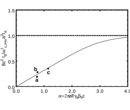
is the effective plasma frequency squared. This self- field parameter limit is similar to a limit that the authors computed for a uniform- focusing magnetic field, Bext =Beˆz [13]. The only difference is that the rms magnetic field on the left- hand side of Eq. (9) should be replaced by B. Figure 2 shows a plot of the right-hand side of Eq. (9) versus the parameter α .In the limit where the bunch spacing is small compared to the pipe radius, i.e. α >>1, the system resembles a continuous beam. Equation (9) becomes
L a b rms , c p b e L a /ω π γ π γ ω2 2 3 2 2 2 4 8 1
2 ≤ − − − − , and recovers the Brillouin density limit for PPM focusing. However, the more relevant limit for high-power klystrons is when the bunch spacing is much larger than the pipe radius, i.e., α <<1. Numerical analysis shows that equation (6) becomes 2ω2p /ωc2,rms ≤2a/γbL, which is much less than the Brillouin density limit.
We now apply the beam confinement condition in Eq. (9) to three recent PPM focusing klystron experiments at SLAC, namely, the X-band 50 MW XL-PPM and 75 MW XP klystrons [7,15] and the W-band Klystrino [16]. The parameters for all three klystrons are listed in Table 1, and their operating points are marked with letter a, b and c in Fig. 2, respectively. The X-band klystrons were designed and tested for the NLC, whereas the W-band klystrino was designed for sub-millimeter radar applications. As shown in Fig. 2 and Table 1, all three klystrons operate in the regime of α <<1 and near
the self- field parameter limit. Because the 50 MW klystron operates slightly below the confinement limit, a mild beam loss still occurs in this device [7] through beam halo formation as reported previously [6,17]. The 75-MW XP is operating outside of the confinement limit. This suggests that the 75 MW klystron has greater beam loss than its 50 MW counterpart, which is consistent with more pronounced X-ray emissions measured at the output section of the device [15]. The Klystrino design parameters fall just inside of the theoretical limit, suggesting a marginally stable beam-wall interaction.
To summarize, we presented a center-of- mass model for a tightly bunched electron beam in a periodic permanent magnet (PPM) focusing klystron. By analyzing the Hamiltonian dynamics of a train of collinear periodic point charges interacting with a conducting drift tube, an rf field, and an applied PPM focusing field, we derived a space-charge limit for the radial confinement of lightly bunched electron beams, which is significantly below the well-known Brillouin density limit for a continuous beam. We found that several state-of-the-art PPM klystrons developed at SLAC operate close to this limit, thereby shedding some light on the origin of observed beam losses. A further study of PPM confinement, which includes multi-particle simulations in each bunch, is needed to make a more accurate estimate on the amount of beam loss in klystrons.
Acknowledgement
This work was supported by the Department of Energy, Office of High Energy and Nuc lear Physics, Grant No. DE-FG02-95ER-40919, and by the Air Force Office of Scientific Research, Grant No. F49620-00-1-0007. The authors wish to thank D. Sprehn and G. Scheitrum for helpful discussions.
References
1. M. Reiser, Theory and Design of Charged-Particle Beams (Wiley & Sons, New York, 1994).
2. R. C. Davidson, Physics of Nonneutral Plasmas (Addison-Wesley, Reading, MA, 1990).
3. Luccio and W. Mackay, eds., Proceedings of the 1999 Particle Accelerator Conference (IEEE, Piscataway, NJ, 1999), and references therein.
4. J. Benford and J. Swegle, High Power Microwaves (Artech, Boston, 1992). 5. R. L. Gluckstern, Phys. Rev. Lett. 73, 1247 (1994).
6. C. Chen and R. Pakter, Phys. Plasmas 7, 2203 (2000), and references therein. 7. D. Sprehn, G. Caryotakis, E. Jongewaard, R. M. Phi1lips, in Proceedings of 19th
International Linac Conference (Argonne National Laboratory Report ANL-98/28), p. 689.
8. F. Hegeler, C. Grabowski, and E. Schamiloglu, IEEE Trans. Plasma Sci. PS-26, 275 (1998).
9. D. H. Fitzgerald, et al., in Ref. 3, p. 518. 10. M. Harrison, in Ref. 3, p. 6.
11. J. J. Barnard, and S. M. Lund, in Proceedings of the 1997 Particle Accelerator Conference (IEEE, Piscatway, NJ, 1997), p. 1929.
12. Gluckstern, R.L., A.V., Fedotov, S. Kurennoy, and R. Ryne, Phys. Rev. E58, 4977 (1998).
13. M.Hess and C. Chen, Phys. Plasmas 7, 5206 (2000). 14. L. Brillouin, Phys. Rev. 67, 260 (1945).
15. D. Sprehn, G. Caryotakis, E. N. Jongewaard, R. M. Phillips, and A. Vlieks, in Intense Microwave Pulses VII, edited by H. E. Brandt, SPIE Proc. 4301, 132 (2000).
16. G. Scheitrum, private communication (2000).
Figure Captions
Fig. 1 Diagram of a periodic array of charges propagating in a perfectly cond ucting cylinder with longitudinal velocity v e . bˆz
Fig. 2 Plot of the maximum value of the self- field parameter (solid curve),
A rms , c b / a I I c2 2 2
8 ω , for bunched beam confinement as a functio n of the parameter c
/ af γbβb π
α 2= . Shown in letters are the operating points for three PPM focusing klystrons: a) 50 MW XL-PPM, b) 75 MW XP, and c) Klystrino. The dashed line denotes the Brillouin density limit for an unbunched beam.
Figure 1 Hess and Chen, PRL
L
r
a
z bˆ
v e
Figure 2 Hess and Chen, PRL
0.0 1.0 2.0 3.0 4.0 α=2πaf/γbβbc 0.0 0.5 1.0 1.5 8c 2 I b / ω 2 c,rms a 2 IA
a
b
c
Table 1. Parameters for SLAC PPM Focusing Klystrons PARAMETER 50 MW XL-PPM 75 MW XP KLYSTRINO f (GHz) 11.4 11.4 95 b I (A) 190 257 2.4 b γ Brms (T) 1.83 0.20 1.96 0.16 1.22 0.29 a (cm) 0.48 0.54 0.04 α 0.75 0.77 1.15 exp A rms , c b I a I c 2 2 2 8 ω 0.19 0.28 0.35 cr A rms , c b I a I c 2 2 2 8 ω 0.238 0.244 0.366