Three-dimensional labels: A unified approach to labels
for a general spatial grammar interpreter
FRANK HOISL1ANDKRISTINA SHEA2
1Virtual Product Development Group, Institute of Product Development, Technische Universita¨t Mu¨nchen, Mu¨nchen, Germany 2Engineering Design and Computing Laboratory, ETH Zurich, Zurich, Switzerland
(RECEIVEDAugust 12, 2012; ACCEPTEDDecember 26, 2012)
Abstract
Spatial grammars are rule-based, generative systems for the specification of formal languages. Set and shape grammar for-mulations of spatial grammars enable the definition of spatial design languages and the creation of alternative designs. The original formalism includes labels that provide the possibility to restrict the application of rules or to incorporate additional, nongeometric information in grammar rules. Labels have been used in various ways. This paper investigates the different uses of labels in existing spatial grammars, both paper based and computational, and introduces a new concept of three-dimensional (3-D) labels for spatial grammars. The approach consolidates the different label types in one integrated con-cept. The main use of 3-D labels is that they can simplify the matching of the left-hand side of rules in parametric grammars. A prototype implementation is used to illustrate the approach through a mechanical engineering example of generating ro-bot arm concepts. This approach more readily enables the use of complex solid geometry in the definition and application of parametric rules. Thus, the flexible generation of complex, meaningful design solutions for mechanical engineering appli-cations can be achieved using parametric spatial grammars combined with 3-D labels.
Keywords: Conceptual Design; Labels; Shape Grammars; Spatial Grammar Interpreter; Spatial Grammars
1. INTRODUCTION
More than 40 years ago Stiny and Gips (1972) introduced shape grammars as a generative approach to shape design. Stiny (1980a) further detailed this concept and subsequently distinguished set grammars as a simple variant of shape gram-mars (Stiny,1982). Since then, a significant amount of re-search has been published on shape and set grammars, both of which can be classified under the more general term “spa-tial grammars” (Krishnamurti & Stouffs, 1993). Originally presented for paintings and sculptures, this concept has also been successfully applied in other domains, such as archi-tecture, industrial design, decorative arts, and engineering. Several authors, for example, Chau et al. (2004) and Cagan (2001), provide overviews of existing spatial grammars.
The formalism for spatial grammars consists of four differ-ent compondiffer-ents, including shapes, an initial shape, rules, and labels. Labels have been used for many different purposes in the definition of grammar rules, for example, to restrict the application of rules or to control the termination of the shape
generation process. The goal of the research presented in this paper is to develop an integrated concept for labels that cov-ers the typical uses of labels and can be incorporated into a visual, interactive three-dimensional (3-D) spatial grammar approach (Hoisl & Shea,2011). A central challenge in the de-velopment of grammar interpreters is the problem of match-ing the left-hand side (LHS) of a grammar rule for complex shapes. Labels can be used to simplify this problem and en-able the consideration of more complex shapes in rule defini-tion and applicadefini-tion.
The paper starts with a background section that introduces the underlying grammar formalism, explains the theoretical aspects of labels, and analyzes the different uses of labels in existing grammar approaches. Next, an overview of the ex-isting 3-D spatial grammar approach is given followed by the introduction of a new concept for 3-D labels. The general uses for labels covered by this concept are then described, fol-lowed by a detailed explanation of how they can be used for the simplification of LHS matching. A software prototype is presented to illustrate the approach through an example in mechanical engineering design. The paper ends with a dis-cussion of the benefits and limitations of the presented ap-proach as well as suggestions for future work.
Reprint requests to: Kristina Shea, Engineering Design and Computing Laboratory, ETH Zurich, CLA F, Tannenstrasse 3, 8092 Zurich, Switzerland. E-mail:kshea@ethz.ch
#Cambridge University Press 2013 0890-0604/13 $25.00
doi:10.1017/S0890060413000188
2. BACKGROUND
2.1. Terminology and spatial grammar formalism “Spatial grammars” is a general term that includes all kinds of grammars that define languages of shape (e.g., string gram-mars, set gramgram-mars, graph gramgram-mars, and shape grammars; Krishnamurti & Stouffs, 1993). This paper focuses on set and shape grammars because the presented approach is based on a set grammar formulation, and among the related existing grammars, there are also several examples of shape gram-mars. With regard to labels, the main topic of this paper, there is no difference between set and shape grammars. The under-lying formalisms of set and shape grammars are similar. Both are generative systems that generate shapes applying defined rules iteratively starting from an initial set or shape that exists within a defined vocabulary of shapes. A set grammar con-sists of four components and is formally defined as G ¼ (S, L, R, I ), where
† S is a finite set of shapes, † L is a finite set of labels, † R is a finite set of rules, and
† I is the initial set, where I is a subset of (S, L)0 . The set of labeled shapes, including the empty labeled shape, is (S, L)0and is also called the vocabulary. The rewrit-ing rules are defined in the form A ! B, where A and B are both subsets of the vocabulary. To apply a rule to a given set of labeled shapes, called the working shape C, first, A in the LHS of a rule has to be detected in C. This matching process can make use of valid Euclidean transformations, t, that are applied to A, to find more possible matches of A in the work-ing shape C. The transformed subset A is then subtracted from C and the transformed subset B of the right-hand side (RHS) of the rule is added, thus resulting in a new set of labeled shapes C0
where C0 ¼ C – t(A) þ t(B).
The formalism of shape grammars is basically the same, where I is the initial shape, A and B are shapes in the vo-cabulary, and rules apply to subshapes of labeled shapes to produce other labeled shapes. In comparison, set grammar rules apply to subsets of sets of labeled shapes to produce other such sets (Stiny, 1982). Therefore, designs generated by a set grammar consist of shapes in S. Designs defined by shape grammars, instead, consist of shapes and subshapes of shapes in S because the compositional units in designs can be decomposed and recombined in different ways (Stiny,
1982). Shape grammars work directly on spatial forms (Krishnamurti & Stouffs,1993), while set grammars treat de-signs as symbolic objects with geometric properties, which makes them more amenable to computer implementation (Stiny, 1982). However, because designs are made up of only symbolic objects in set grammars, in contrast to shape grammars, emergent shapes cannot be recognized nor trans-formed. The more general term spatial grammar is used throughout this paper.
2.2. Labels and their uses in spatial grammars
This section investigates the theoretical aspects of labels, presents a concise overview of common uses of labels, and describes how they are used in existing spatial grammars.
2.2.1. Theoretical aspects
Labels have been applied in various manners in the devel-opment of spatial grammars. Describing labels on a general level, they are used to restrict the ways that rules apply (Knight, 1994), to introduce additional information (Stiny,
1992), to associate nongeometric data (Heisserman,1994), or to classify and distinguish basic elements, like points, lines, planes, or solids in shapes in different ways (Knight,
2003).
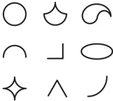
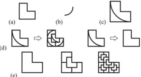
In the first formulation of the shape grammar formalism (Stiny & Gips,1972), the second component of the formalism (cf. Section 2.1) is not explicitly defined as “labels,” but as a second finite set of shapes, called “markers.” In comparison to the first finite set of shapes (cf. S in Section 2.1), which contains terminal shape elements (“terminals”), markers are nonterminal shape elements. The precondition to use the two sets together in the definition of grammar rules is that they are disjoint so that they can be distinguished uniquely. Theoretically, any shape can be used as a marker, as long as it is not a subshape of a shape in the set of terminals or a terminal is not a subshape of a marker. Markers are treated like any other shape during the application of grammar rules, and therefore they can also be altered under Euclidean trans-formations, for example, scaled, translated, or rotated. Fig-ure 1 shows some examples for markers used by Gips (1975) and Stiny (1975).
The definition of a rule contains at least one terminal and one marker in the LHS. Two examples can be seen in
Figure 2d. They are composed using the shape in the set of terminals Figure 2a and the shape in the set of markers
Figure 2b. The set of markers can also contain more than one shape, and differently shaped markers can be used in one side of a rule. The first role of markers described in the early shape grammar work (Stiny & Gips, 1972; Gips,
1975; Stiny, 1975,1976) is to restrict rule application to a specific part of the current working shape (CWS; called C0
Fig. 1. Different examples for markers (according to Gips,1975; Stiny,
1975).
F. Hoisl and K. Shea 360
https:/www.cambridge.org/core/terms. https://doi.org/10.1017/S0890060413000188
in the formalism in Section 2.1). In this context, they can also be defined in a way that rules are applicable only once to any added shape. If there is no marker in the LHS of a rule, the rule might be applicable over and over to a shape. For exam-ple, without the marker, the first rule shown in Figure 2d
could be applied more than once to the outer L-shaped geom-etry starting with the initial shape (Fig. 2c).
The second role of markers is to represent nonterminal shape elements and control the termination of the shape gen-eration process. For this purpose, in each grammar a rule is defined that results in the removal, or erasing, of existing markers in the CWS. For example, the second rule shown in Figure 2d serves this purpose. With no markers left in the CWS, no further rules in the grammar are applicable, and the generation process stops. Depending on when this rule is applied, different solutions are generated in the design language, for example, the three different designs illustrated inFigure 2e.
The third role of markers is to help determine the transfor-mations required to apply rules. This comprises not only the location but also the relationship in orientation and scale be-tween the rule applied and the shape to which it is applied. In this context, a marker can also remove symmetries (rotational and reflective) of a shape. Asymmetric markers, for example, the top right marker shown inFigure 1, can be used to force the rule application to a certain orientation. Further, the use of a marker can prevent infinite matches, for example, matching a shorter line in a longer line under translations or, in the case of shape grammars, matching rotationally symmetrical geo-metric objects under rotations.
The further specification of the shape grammar formalism (Stiny,1977,1980a) uses an adapted formulation as the one presented for set grammars in Section 2.1. Here, the second component of the formalism is defined as a finite set of sym-bols. Association of a symbol to a point results in a labeled point, commonly referred to as “label.” In comparison to a marker, a label, or the symbol associated with a point, is in-variant under Euclidean transformations. As a result, there are differences regarding the determination of the transforma-tions required to apply rules (cf. third purpose described above). In general, however, the function of a label is also to help guide the shape generation process. Labeled points are used the same way as markers to define rules. A rule
con-tains a labeled shape on both the LHS and the RHS (e.g.,
Fig. 3a). The labeled shape consists of a shape and a set of la-beled points. If this set is empty, no symbols are associated with the shape (Stiny,1980b), resulting in an unlabeled shape (e.g.,Fig. 3b). The other way around, labels may also be as-sociated with the empty shape, resulting in a “blank space” with only labels in it (e.g.,Fig. 3c).
It is further possible to define labeled parameterized points whose coordinates are not static values but variable. This con-cept is especially important for the definition of parametric shape grammars. Here the rules are based on parameterized shapes, and some or all of the parameter values are not prede-fined in the rule. Thus, a rule schema is deprede-fined that describes many different but related rules in one generalized rule (cf. Stiny,1980a).
On the basis of these definitions and uses of labels, to date, labels have been applied in a wide range of scopes and have been represented in many different forms. The most common way to represent a label is a dot, or a small circle, that might be filled or empty. Other geometrical entities like squares and cylinders for 3-D rules have been used as well. In addition to geometrical shapes as symbols for labels, characters, or let-ters, and numbers have been used, often in combination with a geometrical symbol.
Knight (1983,1994) defines two categories of labels: spa-tial labels and state labels. Spaspa-tial labels are used to control where (i.e., the relative position in relation to a distinct sub-shape) and how (i.e., under what specific Euclidean transfor-mations) rules apply to a CWS. Spatial labels have a specific location, but unlike shapes or the original idea of markers, their orientation or size has no influence and is invariant if a rule is applied under rotation or scale transformations. Often spatial labels are used to prevent application of rules to the same shape more than once or to make rules applicable only to the most recently added shape in a CWS. Another, very specific use is to define spatial labels in rules such that the shapes cannot interpenetrate each other once inserted in the CWS (Stiny,1980b).
Figure 4ashows an example for a rule using spatial labels that combine the described purposes. Applying the rule to the initial set inFigure 4b, the label depicts the one transforma-tion under which the rule is to be applied. Without using a la-bel, there would be several different rotation or reflection transformations to match the rectangle. Applying the rule a
Fig. 2. An example of a shape grammar using markers (according to Stiny,
1975).
Fig. 3. Different uses of labeled shapes in shape grammar rules (based on Stiny,1980a).
second time, the label forces the LHS to match under a com-bined reflection and rotation transformation. Further, the LHS can only be matched to the rectangle with the label (i.e., the most recently added shape), and therefore the rule can only be applied once to any shape that is added to the CWS.
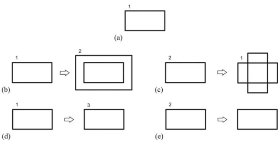
State labels are the second category defined by Knight (1994). They are used to define when rules apply or, more pre-cisely, the sequence and the repetition (i.e., implicitly), the number of times a rule could be applied. This can also include the termination of the generation process, for example, if there are no further labels in a CWS, therefore no further rule is ap-plicable. State labels are completely nonspatial (i.e., in com-parison to spatial labels, not even the location matters). Often they are represented using numbers.
Figure 5illustrates several rules using state labels. If only Rule (b) is defined in a grammar, it can be applied once to the initial set (a), whereas the state changes from “1” to “2.” This prevents further application of the rule, restricting the number of possible iterations. Adding a second Rule (c) to the grammar with a state label “2” in its LHS, the applica-tion is no longer restricted to a single iteraapplica-tion. Because the application of the rule changes the state back to “1,” the rule sequence is determined to apply Rules (b) and (c) repeat-edly one after the other. To terminate the generation process, Rule (d) can be applied that changes state “1” into state “3.” This state is not part of any of the other rules, and thus, no fur-ther rule can be applied. Similarly, Rule (e) can be applied. This rule does not change the state but instead completely re-moves the label.
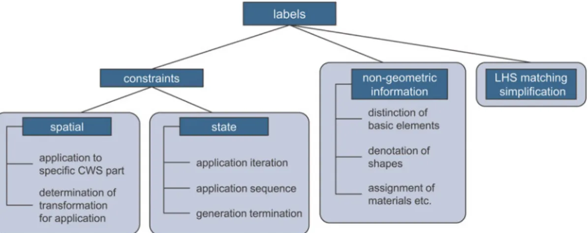
More than one label and also different kinds of labels (spa-tial and state) can be defined on either side of a rule. The only precondition is that the set of spatial and the set of state labels used in a grammar are disjoint. The different uses of labels de-scribed so far are summarized in the left branch, “con-straints,” ofFigure 6. Generally speaking, these uses of labels all introduce constraints restricting the application of rules.
However, labels can also be used to augment shapes with additional, nongeometric information or data. For example, they can distinguish or classify basic elements and parts of shapes, or they may have their own semantics to introduce other kinds of properties (Stiny,2006). Other examples are the use of text labels for the denotation of shapes, which can also be used to assign semantic or functionality to shapes. In the same way, labels can assign, for example, materials to solids that can be used to calculate the mass or render the tex-ture and color of a solid (Heisserman,1994).
For example, rule (a) in Figure 7 adds the textual label “shaft” to a cylinder so that it differs from other cylindrical objects and gives semantic meaning to the geometry. A fur-ther rule could be defined that only applies to a “shaft” and no other cylinder. Similarly, rule (b) augments the block with information about its material.
The last category of labels shown inFigure 6is the simpli-fication of the LHS matching of a rule in the CWS. For the computational implementation of grammars, the LHS match-ing problem is a central challenge (Krishnamurti & Stouffs,
1993), because the computer relies on formal representations of geometry that are not sufficiently suited to detect visual similarity of geometry under Euclidean transformations in a general way. This is especially true for curved shapes (Jowers & Earl,2011). In paper-based grammars, matching the LHS in the CWS relies on the human ability to recognize the equal-ity of possibly parametric (sub)shapes under Euclidean trans-formations. The computational complexity of the matching operations means that the shape grammar formulation of spa-tial grammars does not lend itself well to computer imple-mentation (Heisserman, 1994). Set grammars, which the approach presented in Hoisl and Shea (2011) is based on
Fig. 4.A rule using (a) spatial labels and (b) an initial set.
Fig. 5. The (a) initial shape and (b–e) rules using state labels.
F. Hoisl and K. Shea 362
https:/www.cambridge.org/core/terms. https://doi.org/10.1017/S0890060413000188
(cf. Section 3.1), are more amenable to computer implemen-tation. Nevertheless, difficulties in the implementation of the LHS matching exist regarding, for example, the calculation of the transformations, recognition of complex geometries, and parametric rules. The latter two issues are especially impor-tant to generate meaningful geometry in engineering because in this area shapes are usually not only simple orthogonal lines or blocks (Cagan,2001) and there is a great need for modeling constraints in rules.
A few examples for spatial grammars exist that, while using curves, avoid shape matching entirely by relying on la-bels (McCormack & Cagan, 2006). In the example in Fig-ure 8, the problem of matching curved geometry is circum-vented using a combination of a straight line and a label in the LHS of Rule (a). Instead of having to match curved geom-etry in the CWS (b), only the label and the straight line have to be matched.
The label in (b) indicates that a further rule has to be ap-plied (i.e., the CWS with the straight line is an intermediate stage). The straight line acts as a reference, because only using the label in the LHS would not depict the rotation under which the rule has to be applied. In general, the reference does not necessarily have to be a line, but multiple options using points and lines are possible to achieve this goal. The appli-cation of the rule results in the curvilinear design in (c). It
can be seen that this label type is an extension of the spatial label.
2.2.2. Labels in existing spatial grammars
In this section several concrete examples for labels in exist-ing set or shape grammars both on paper and in computer im-plementations are investigated. The examples show different aspects and uses of labels.
Paper-based grammars. Many spatial grammars using la-bels exist on paper. One of the early examples is the ice-ray grammar that generates Chinese lattice designs (Stiny,
1977). In this parametric grammar, labels are represented as simple dots and are exclusively used to prevent the applica-tion of rules to the same polygon more than once. Knight (1980) presents a grammar for the design of Hepplewhite chair backs that uses different kinds of parametric labels rep-resented, for example, by letters, dots, or star symbols. They are mainly spatial labels because they depict the positions in which lines are added to the CWS, but also rules are used that remove the labels from the CWS to guide the termination of the generation process. A third example is the 3-D kindergar-ten grammar (Stiny,1980b). The main purpose of using la-bels in this grammar is the determination of the transforma-tions under which the LHS of a rule can be matched. The paper discusses many examples of different symmetries of the blocks; the labels, therefore, depict the rotation or reflec-tion transformareflec-tions.
Fig. 6. (Color online) Concise overview of the use of labels.
Fig. 8.Example using simplified left-hand side matching. Fig. 7.Rules with labels adding nongeometric information to geometry.
In the field of architecture, many spatial grammar examples exist that make heavy use of labels (e.g., Downing & Flem-ming,1981; Flemming,1987; Duarte,2005). In the grammar developed by Koning and Eizenberg (1981) for the genera-tion of prairie houses in the style of Frank Lloyd Wright, la-bels are represented using a range of different letters and sym-bols. Several of them depict the rule sequence. For example, the generation always starts with the introduction of the fire-place, followed by the living zone, and subsequently adding a service zone. Labels determine the location where rules can be applied and sometimes the transformation under which the new part of the house is added to the CWS. Other labels distinguish the functionality of different parts of the house, which are spatially defined as compositions of rectangular blocks.
Among the more recently published grammars, there are several stemming from the engineering design domain. For example, Pugliese and Cagan (2002) present a grammar that creates different side views of Harley-Davidson motor-cycles, in which labels guide the designer in the selection of the rule sequence. In the Buick grammar (McCormack et al., 2004) that generates front views of the Buick car, some of the start or end points of curvilinear shapes are la-beled with additional information about representing “sharp” or “soft” transitions concerning the continuity of the line flow to the next line segments. The latter two approaches for gram-mars are merged in the work presented by Orsborn et al. (2006). A rule in this grammar consists of front, side, and rear views of a vehicle arranged next to each other. One and the same label can occur in several views in parallel. The majority of the labels have a spatial and a state label char-acter at the same time. By using a numbering system, they are defined to drive the rule application so that feasible solutions are generated that contain the main characteristics of a vehicle design.
Implemented grammars. The majority of implemented spatial grammars allow for the definition of labels; however, not all do. In comparison to paper-based definitions where the developer of a grammar can draw any kind of symbol to repre-sent a label, labels in computer-based implementations are predefined objects in the system. For the use in implemented systems that allows the user to define new rules, it has to be assured that there is no chance that labels can be recognized by the system as “normal” shapes (i.e., it is necessary that the two sets are disjoint). In some cases, labels are represented using general geometric objects that are then not used in the definition of the shapes in the rules, similar to the original definition in Stiny and Gips (1972). For example, in two di-mensions a filled circle or in 3-D a cylinder with a certain dia-meter are often used as the symbols for labels. Internally, it must be clearly defined which geometric objects define shapes and which define labels.
Many of the existing systems were hard-coded for one spe-cific grammar, “meaning that a computer program was cre-ated entirely to implement a single set of rules” (McCormack
& Cagan,2003). One example is the coffee maker grammar (Agarwal & Cagan,1998) that makes use of labels to control the generation process. Labels are defined using a wide range of letters and numbers, sometimes in combination with dots, squares, or triangles. Most of these labels have spatial label character determining the location where rules apply. The la-bels that depict functional entities, such as the filter or the wa-ter storage unit of the coffee makers, incorporate state label functionality because they force the generation process to consider a certain subset of rules of the grammar. The imple-mentation of the grammar further relies on labels to circum-vent the need to match curvilinear lines (cf. McCormack & Cagan,2006). A similar combination of spatial and state la-bels is used in an implementation for the application of rules that generate sections of two-dimensional Chinese wood-frame buildings (Li & Kuen,2004). In many cases the genera-tion of the building geometry terminates even if further labels are existent, but several rules are available to remove remain-ing labels from the CWS. Another example that uses labels to guide the application process is a grammar for the generation of microelectromechanical devices (Agarwal et al.,2000). In this example, labels also help to distinguish between lines representing springs, anchors, actuators, and mass, as well as the inside and the outside of a shape. Using a form–func-tion coupling, labels are used to ensure that some indispensa-ble functional entities exist in any final design solution.
During the last 15 years, an increasing interest in imple-menting more general spatial grammar systems can be seen. Several of them incorporate the use of labels. In the GEdit system (Tapia,1999) shape rules can contain labels to restrict the application of rules to a certain shape or to deal with re-flection symmetries. They are drawn as ovals that can be filled with different patterns to define a variety of labels. In Sha-per2D (McGill & Knight,2004), labels are used exclusively to remove symmetry of shapes. Their position can be changed to different predefined locations that are dependent on the de-grees of the symmetry of a particular shape. Deak et al. (2006) implemented a system that is based on straight lines. These lines can be distinguished by assigning different line types that can be seen as augmenting labels. Another implementa-tion that is based on straight lines was published by Trescak et al. (2009) and allows for the definition of dots that are used as spatial labels in rules.
Concerning 3-D systems, Heisserman (1994) uses labels to restrict rule application in his Genesis system that was used to generate, for example, alternative Queen Anne houses. Text-ual labels are also used to introduce nongeometric data (e.g., to distinguish between different kinds of rooms). The 3-D in-terpreter presented by Piazzalunga and Fitzhorn (1998), which implemented grammars such as the Sierpinski gram-mar, used labels represented by single letters. The labels are used to restrict the application of rules to a certain geometric object, to remove symmetries, and in some cases to define a certain rule sequence. Spatial and state functionality are sometimes combined in one label. An example for using la-bels to introduce additional, nongeometric information can F. Hoisl and K. Shea 364
https:/www.cambridge.org/core/terms. https://doi.org/10.1017/S0890060413000188
be found in Starling and Shea (2002). The grammar distin-guishes structural elements by assigning text labels, for exam-ple, “disk,” “spindle,” or “plate” to cylindrical primitives. In 3DShaper (Wang & Duarte,2002), labels are defined to elim-inate the ambiguity in shape rule applications that arises due to the symmetry of blocks. The position of a label can be set to one of the corners of a specified block. During generation, these labels are not removed. Rules are applied to the most re-cently added block because the rule sequence is predefined in the way the grammar is implemented and not through guid-ance from labels. The SGS system by Chau et al. (2004), which allows for the generation of 3-D wireframe models, uses dots in combination with different single letters as labels to restrict rule application to certain parts of the CWS and to remove symmetries. Based on the use of letters, the labels can also be used to realize state labels. The implemented example of a Coca-Cola bottle grammar uses straight lines and labels in the LHSs of the rules to circumvent problems with match-ing curvilinear lines. The latest prototype implementation of a 3-D grammar system, Grammar Environment (Li, Chau, et al.,2009; Li, Chen, et al.,2009), is based on the system by Chau et al. (2004) and provides the same functionality with respect to the use of labels.
3. 3-D LABELS
The concept described in this paper is used to enhance a com-puter-based approach for the development and application of spatial grammars, which was previously presented by the au-thors in Hoisl and Shea (2011). The definition of labels for all potential uses, as defined in Figure 6, during rule develop-ment is enabled within the spatial grammar interpreter.
In this section, first, the basics of the existing spatial gram-mar interpreter are briefly described, because they are impor-tant for the understanding of the remainder of the paper. Sec-ond, the concept of 3-D labels is introduced, and different uses are presented with a focus on simplifying the matching of the LHS of parametric rules that include complex shapes. 3.1. A visual and interactive approach to developing
and applying spatial grammars
The approach presented in Hoisl and Shea (2011) provides a flexible platform supporting designers with visual, interactive definition and application of their own grammar rules without programming (Fig. 9). The underlying ideas of this approach are the basis for the label concept presented in this paper. The approach is based on a set grammar formulation of spatial grammars and supports the definition and application of non-parametric and non-parametric rules. The vocabulary consists of a set of parameterized 3-D primitives, namely, box, torus, cone, cylinder, sphere, and ellipsoid.
For the definition of a rule, a number of primitives are in-serted on each side of the rule (i.e., LHS and RHS), and their parameters are specified. The parameters describe the size as well as the location and orientation of the objects. Every
primitive geometric object that is created has its own local coordinate system. This coordinate system and, therefore, the attached object itself can be translated and rotated in rela-tion to the global coordinate system. This informarela-tion is kept in a transformation matrix. A rule is designed such that there is one reference object in the LHS, which is located in the global origin and must not be rotated.Figure 10provides ex-amples for a nonparametric rule (above) and a parametric rule (below).
To create parametric rules, one or more of the objects’ pa-rameters are “unlocked.” These “free papa-rameters” can be size parameters, like width, length, and radius, but also location parameters defining the translation of an object in the x, y, and z directions or orientation parameters defining the rota-tion as “yaw, pitch, and roll.” By default, unlocked parame-ters are completely unrestricted (i.e., any value can be as-signed to them). Further, parametric relations in the form of mathematical equations can be defined between free parame-ters. Another possibility is to restrict the values that are al-lowed to be assigned to a free parameter to a certain range. In the latest version of the prototype system (see http://source-forge.net/projects/spapper/), real values can be defined not only as range limits but also as parametric relations. In addi-tion, one of the limits can be kept blank if only a lower or up-per bound is required. These mechanisms for defining and re-stricting free parameters allow for the visual definition of parametric grammar rules in a computational system. As in the original definition of parametric shape grammars (Stiny,
1980a), rule schema can be defined. Using mathematical equations, specific constraints can be incorporated into rules, which is especially important when developing spatial gram-mar rules for engineering design tasks.
For the application of a rule, automatic matching of the LHS of a rule in a CWS is carried out along with the calcula-tion of the posicalcula-tions and sizes of the objects in the RHS ac-cording to the defined parametric relations. The approach for the matching finds all possible matches of the LHS of a rule in the CWS. It starts with detecting the reference object of the LHS using a comparison of the objects’ primitive types and an equality check of the size parameters, which may in-volve the evaluation of free parameters in the case of a para-metric rule. If there is more than one object in the LHS, the remaining objects in the LHS are checked for matching in the CWS. The procedure is the same as for matching the ref-erence object, but the spatial relation between each of the ob-jects and the reference object has to be equal to the spatial re-lation of the objects detected as matches in the CWS. This is checked by calculating and comparing the relative transfor-mation matrices between the involved objects. Finally, one of the found sets of matched objects is selected to be replaced by the RHS of the rule. According to the equation C0 ¼ C – t(A) þ t(B) (cf. formalism in Section 2.1), all of the rules are realized as replacement rules (i.e., even in case of additive or subtractive rules, the matched LHS is fully subtracted from the CWS and replaced by the transformed RHS). The new po-sitions of the RHS’s objects are calculated based on the
de-Fig. 9. (Color online) A screenshot of the prototype software system during the definition of a rule. 366 https:/www.cambridge.org/core/terms . https://doi.org/10.1017/S0890060413000188 Downloaded from https:/www.cambridge.org/core
. University of Basel Library
, on
30 May 2017 at 15:51:10
tected transformation of the LHS match, including the deter-mination of the values for any free parameters in the case of a parametric rule.
In addition to the approach described by the authors in Hoisl and Shea (2011), the latest version of the prototype im-plementation, which is based on a computer-aided design (CAD) system, is also able to operate on objects generated using Boolean operations and sweeping operations based on cross sections made up of straight lines (Hoisl, 2012). Both capabilities extend the complexity of geometric objects that can be used for the definition of parametric rules and, as a consequence, the range of possible designs that can be gener-ated.Figure 11illustrates one example rule and generated de-sign for each of the two techniques. The “rings” used in the example in the LHS of the figure are created using a Boolean difference operation of two cylinder primitives.
3.2. 3-D labels
The principles described in Section 3.1 are the basis for the enhancement of the approach with a unified label concept
for a spatial grammar interpreter. As with the other geometric primitives that can be used in this spatial grammar approach, a label is specified such that it has its own local coordinate sys-tem (Fig. 12). This enables the determination of the location of a label using translation transformations. In addition, how-ever, it enriches the label with information about its orienta-tion in 3-D space based on the possibility to change the rota-tion parameters. Similar to the idea of asymmetric markers (cf. Section 2.2.1), this has an influence on the detection of the transformation required to apply a rule. Because these la-bels carry information about location and rotation in 3-D space, they are denoted “3-D labels.”
In the approach presented in this paper, labels do not have any geometric properties but only carry transformation infor-mation. Hence, it is automatically assured that the set of shapes S and the set of labels L are disjoint. Internally, labels have no solid geometry representation in the underlying CAD kernel, in contrast with the geometric primitives that define the set of shapes S. The sphere that can be seen inFigure 12
only exists for visualization purposes (i.e., it is merely dis-played in the graphical user interface to ease the work with labels for the user of the spatial grammar interpreter). Hence, it also cannot be detected as a match of a sphere object by the automatic LHS search during rule application.
Fig. 10. (Color online) Examples of (top) a nonparametric rule and (bottom) a parametric rule.
Fig. 11. Examples for rules and generated designs using (left) Boolean
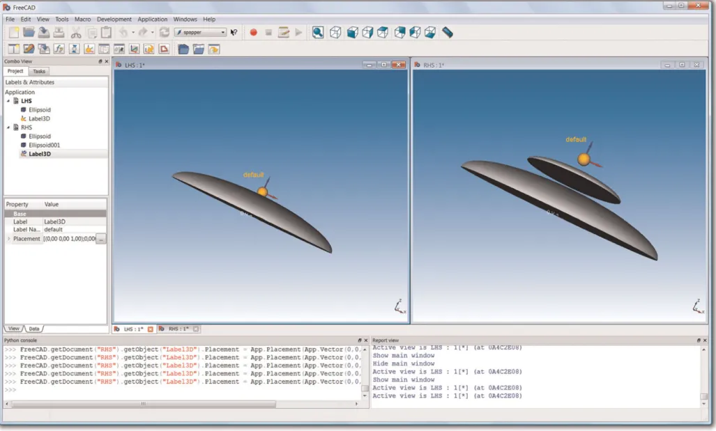
Without having any geometric properties, it is not possible to differentiate 3-D labels by means of their shapes. Instead, the approach provides the possibility to assign different colors to a label. The effect is the same as using different shapes. At the same time, it simplifies the automatic matching of a label, because no shape needs to be matched but only the symbolic numbers of the color values. Besides the color, a “label name” can be defined as an additional property. This allows for assigning a letter or a number to further distinguish labels. The label name is not restricted to one single character or number but can consist of a string of arbitrary length and therefore enables the possibility to introduce a wider range of additional information in a grammar rule in textual form. When inserting a new label to a rule, the name is set to the standard name “default” (cf. Fig. 12). It is also possible to erase it and therefore use labels without names as well.
In principle, 3-D labels have the same behavior as any other primitive in the approach. For example, they can be the refer-ence object in the LHS of a rule or define different spatial re-lations together with other geometric objects. The application, including the matching of several objects and their relative transformations, stays the same as described in Section 3.1. It is also possible to define free parameters, the same way as explained for the definition of parametric grammar rules. Because labels do not have any geometric parameters, only the translation or rotation parameters can be “unlocked.”
A 3-D label is not directly assigned to a shape (i.e., there is no explicit connection defined between the two). Instead, an affiliation can be implicitly given by the spatial relation be-tween a label and a shape. A spatial relation other than the one defined in the LHS of a rule (i.e., a different relative trans-formation), would not be detected as a match in the CWS. 3.3. General uses for 3-D labels
The concept of 3-D labels introduced in the previous subsec-tion can be used for the common applicasubsec-tions of labels as summarized inFigure 6. For use as a spatial label, only the information about the location but not the orientation is rele-vant. Unlocking all three rotation parameters and making them unrestricted makes a 3-D label a “conventional” spatial label. Using a label in this way, the application of rules can be restricted to a specific part of the CWS, for example, to the most recently added box, as illustrated inFigure 13. This ex-ample was previously presented by the authors (Hoisl & Shea,2011) to demonstrate the use of parametric grammar rules. Without labels, it is necessary to manually choose one of the matches to avoid applying the rule to one specific box more than once. Using labels in the definition of the rule (Fig. 13a) enables the automatic generation of the design in
Figure 13c. The application starts by matching the LHS of the rule to the initial shape shown inFigure 13b, which con-tains a randomly oriented 3-D label. It can be matched be-cause the orientation for a spatial label is not important (i.e., the rotation parameters of the label in the LHS of the rule are all unlocked, or free).
For use as a state label (cf.Fig. 6), in addition to the rotation parameters, the location parameters are set as unrestricted to make the label completely “nonspatial” (i.e., neither the loca-tion nor the orientaloca-tion matter but only that the label exists). The label is then assigned to a rule side rather than to a spe-cific shape. Using 3-D labels as state labels, rules can be de-fined in a way that the labels implicitly determine the rule ap-plication sequence if different kinds of colors and label names are used. In addition, the number of rule iterations or the ter-mination of the shape generation process using a rule that erases the existing label(s) can be controlled. InFigure 14, for example, the rules can only be applied iteratively
accord-Fig. 13. (Color online) A three-dimensional label used as a spatial label to restrict rule application to the most recently added shape in the current working shape.
Fig. 14. (Color online) Some three-dimensional labels used as state labels.
F. Hoisl and K. Shea 368
https:/www.cambridge.org/core/terms. https://doi.org/10.1017/S0890060413000188
ing to the sequence (a)–(b)–(c) because of the labels. Rule (d) can be used to abort the generation process after three, six, nine, and so on rule applications.
In comparison to this “internal” guidance for the rule appli-cation, the previously presented approach (Hoisl & Shea,
2011) provides “external” possibilities to guide the applica-tion of rules without the necessity of using state labels. The sequence of rules can be defined in a resortable list of loaded rules. The number of rule applications and therefore also the termination of the generation process can also be explicitly specified. Further, both state labels and the external function-ality to guide the application process can be used together.
These 3-D labels can also be used to add nonspatial infor-mation to rules (cf.Fig. 6). Developing a new rule, one has to decide whether the additional information is relevant for the LHS matching process during the application of the rule or not. Depending on this choice, the different transformation parameters can be set as unrestricted or restricted. Most important for the augmentation of shapes is the additional “la-bel name.” It can be used to classify or distinguish shapes or to add in a semantic meaning for a shape. The label name can also represent pure textual information that does not have any influence on the rule application but rather remains in the geo-metric model after design generation is finished. In this re-gard, such labels can be informative by adding information about design intent and manufacturing, for example, toleran-ces or welding information, measurement details, materials, texture, and colors.
The last possible use of labels, the simplification of the LHS matching, is discussed in more detail in the next subsection. 3.4. Using 3-D labels for simplified LHS matching As mentioned at the end of Section 3.1, the latest version of the spatial grammar interpreter enhances the approach descri-bed by the authors in Hoisl and Shea (2011) with the possi-bility to use Boolean operations on objects and simple swept objects for the definition of parametric rules. This is a step to-ward generating more meaningful geometry for mechanical engineering design tasks. However, solids commonly used in mechanical engineering can be topologically more com-plex or even derived from free-form surfaces and include a wide range of detailing geometry (e.g., fillets and chamfers). Spatial grammar rules based on such complex geometry are difficult to handle, generally, in an implemented system, es-pecially an interpreter, because of the issues regarding auto-matic matching of the LHS (cf. Section 2.2.1).
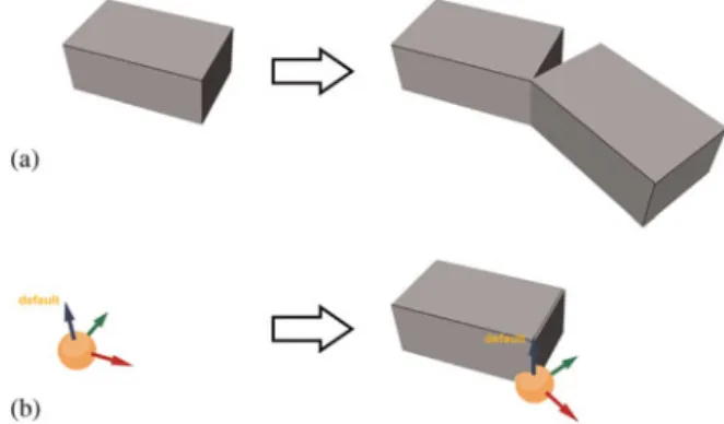
The 3-D label can possibly be used as a ‘substitute’ for ge-ometry in the LHS and therefore circumvent the difficulties with the automatic matching of the LHS. In comparison to the example shown inFigure 8where the straight line is an implicit reference to determine the orientation under which the RHS of the rule has to be added to the CWS, it is not ob-ligatory to have any shape in the LHS in addition to the 3-D label. This is because the 3-D label, as introduced in the ap-proach in this paper, also carries information about
orienta-tion. The abstract additive rules inFigure 15symbolize the difference between a “conventional” rule (a) and a rule that contains only a 3-D label in the LHS (b). Application of both rules results in the same solution assuming that rule (b) is applied one more time than rule (a).
For a 3-D label that might exist in the RHS, like the one shown in the example inFigure 15b, a parametric relation can be de-fined, so that, for example, its location is dependent on an unrest-ricted parameter of one of the shapes in the RHS. It then impli-citly depicts the location of the next rule to be applied in relation to the geometry in the RHS of the currently applied rule.
Rules developed based on this approach can contain an ar-bitrarily complex, parametric RHS and can be applied as long as the 3-D label in the LHS can be matched.
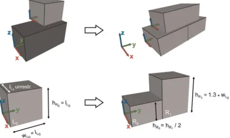
3.5. Segments
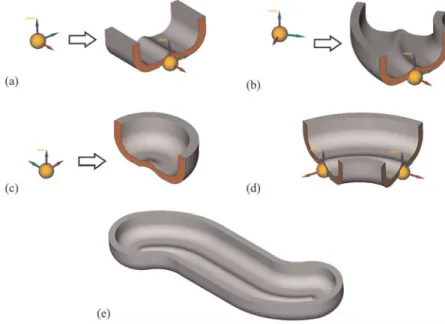
Circumventing the difficulties of the LHS matching with 3-D labels allows for the use of more complex geometry in a spa-tial grammar. To generate meaningful mechanical engineer-ing parts usengineer-ing 3-D labels for simplified LHS matchengineer-ing, it is necessary that the interfaces between the shapes in the dif-ferent rules are assured to fit once they are inserted in a de-sign. Shapes with specified interfaces are denoted “seg-ments” in the approach presented in this paper. They are the subparts, or building blocks, used to generate mechanical en-gineering parts, as symbolically illustrated inFigure 16.
This concept has an analogy to an approach often used in variant management, called modular construction or
assem-Fig. 15. (Color online) (a) A conventional rule and (b) a rule with only a three-dimensional label on the left-hand side.
Fig. 16. (Color online) Segments and their interfaces used to compose a me-chanical engineering part.
bly systems (see, e.g., Ulrich,1995; or Pahl et al.,2007). In modular systems, the aim is to define a limited number of ba-sic building blocks, or modules, with well-defined interfaces, so that they can be combined to define a large range of product variants. Often these building blocks are derived from existing, related product variants by extracting their commonalities. The extraction and definition of building blocks from existing designs is also applicable for the defini-tion of segments. Ideally, in modular systems, the parts or subassemblies are used more than once in one product, and the intention with segments in this work is the same (see
Fig. 16). In comparison to modular systems that operate on the assembly or product level, the segment concept is used to generate geometric models of parts through a series of in-terfaced segments. To allow for more complex part composi-tions, it is useful to define more than one type of interface to-gether with different kinds of labels in the definition of rules. Three example rules that use 3-D labels in the LHS and segments with complex curved geometry in the RHS are shown inFigure 17a–c. The initial setFigure 17dcontains an-other segment and two 3-D labels. The interfaces of all seg-ments are identical. An example for a solution generated ap-plying the rules is shown inFigure 17e.
Because the geometry in the RHS is of no relevance for the further application of rules in a CWS, there are basically no restrictions on how segments are created. CAD systems usually provide many modeling concepts that can be used for designing segments. The most common approach in com-mercial mechanical engineering CAD systems is feature-based parametric modeling. Features are high-level paramet-ric modeling entities that have some engineering significance and ease the design of recurring shapes (Shah & Ma¨ntyla¨,
1995). The “standard” features most commonly provided by mechanical engineering CAD systems are fillets,
cham-fers, pockets, holes, and so forth. A segment can be modeled using different features together with parametric primitives, Boolean objects, or other advanced parametric modeling techniques like sweeps along 3-D trajectories, lofts for the generation of solids, or parametric free-form surfaces, to de-rive solids. An extended feature concept that is often allocated to the area of knowledge based engineering is user-defined features (UDFs). UDFs enable designers to define their own customized compound features (e.g., see Hoffmann & Joan-Arinyo,1998). These help to facilitate the design of fre-quently occurring, similar subparts of geometric models, as needed, for example, in product variants. A UDF can be com-posed of different standard features and might contain para-metric relations and parameters that can be changed to in-stantiate the geometry of the UDF once it is inserted in a design. In conventional CAD design, the designer has to po-sition the UDF in an existing model and manually define the required reference elements. Using UDFs as segments for the definition of rules with a 3-D label in the LHS enables their automatic addition to an existing design based on the transfor-mation infortransfor-mation of the 3-D labels.
4. EXAMPLE: ROBOT ARM CONCEPTS
An example for spatial grammars focusing on simplified LHS matching is created using the prototype spatial grammar inter-preter to demonstrate the conceptual application of the ap-proach. The example is able to generate different complex geometry solutions for robot arm concepts. A robot usually consists of several robot arms that can be rotated around dif-ferent axes. These robot arms have to be designed in a way that they fulfill requirements concerning stability, weight, de-sign space, and so forth. Here, the application is approached only conceptually as an example for complex, 3-D design
Fig. 17. (Color online) An example of a spatial grammar using three-dimensional labels and segments.
F. Hoisl and K. Shea 370
https:/www.cambridge.org/core/terms. https://doi.org/10.1017/S0890060413000188
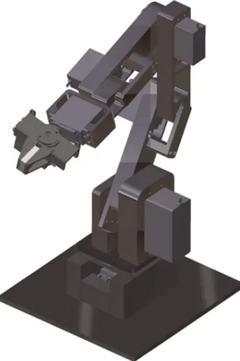
generation in a mechanical engineering related area. The spa-tial grammar is intended at this point to illustrate and validate the 3-D label approach rather than validate the grammar itself (i.e., in terms of the design space defined). The grammar rules for this example were derived by analyzing existing industrial robots, for example, the one shown inFigure 18, in terms of part geometry, modularity, and joining of parts to create a complete robot arm assembly.
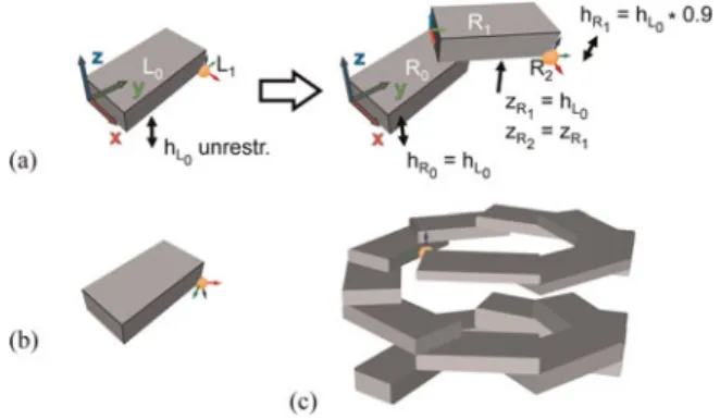
Figure 19shows the spatial grammar developed based on the approach of using 3-D labels for representing spatial constraints, state constraints, nongeometric information, and simplified LHS matching of different segments of robot arms. The gram-mar is not hard coded but rather developed and applied within the spatial grammar interpreter prototype developed by the authors (seehttp://sourceforge.net/projects/spapper/).
Rule (a) is the first rule to be applied. It uses the starting symbol in the LHS to start from the empty shape (i.e., no ge-ometry) and adds a segment consisting of a parametric joint as well as the first part of the robot arm with a specified inter-face. In addition, a default 3-D label is defined in the RHS so that further rules can be applied. This label serves both as a state label and to simplify the LHS matching through
specif-ication of the translation and rotation transformations needed such that the segment added in the RHS is aligned with the previous segment. The radius, r, is defined to be within a range of 30 to 40 mm, so that the diameter of the joint can be adapted (e.g., depending on the load the arm has to resist). The translation, translateY, of the joint depicts the offset of the joint’s center from the label and is set depending on the radius. Rules (b)–(e) and (h) can be applied after this first rule because they all have a default label in the LHS. The RHS of rule (b) consists of a bridge segment that extends the length of the robot arm. It is based on an extrusion in the y direction, dirYb, which is restricted to a range between 30 and 100 mm. In addition, it contains a stiffener that is po-sitioned in the middle of the extruded part (translateYs) and can be rotated within a range of +158 around the x axis (rolls) depending on the main direction of the force application on the robot arm. A second stiffener on the backside of the part is positioned according to the first one. Rule (c) adds an-other bridge segment that includes a narrowed cross section in the middle. It can help in cases where the weight of the robot arm has to be reduced or the load on the arm is not high. The length of this middle part of the segment is parametric and re-stricted by a range. Rule (d) allows for extrusions in three dif-ferent directions, dirX, dirY, and dirZ, that are all restricted to certain ranges. In cases where dirX and dirZ are zero, the rule is identical to rule (a), except with the addition of stiffeners. Application of the rule results in a deviation of the main robot arm direction from the y axis. This can be needed in cases where the available space for the robot arm is restricted, for example, to avoid collisions with other obstacles. Rule (e) is geometrically and parametrically identical to rule (b). The difference is that it introduces a new kind of label that car-ries a different color and the name “split,” and therefore also changes the state. In addition, not one, but two, of these labels are defined in the RHS of this rule. After applying this rule, none of the previously described rules or rule (h) can be ap-plied, because the default label in the LHSs (i.e., its name and color) can no longer be matched. Instead, only the two rules (f) and (g) are applicable. The first one adds a smaller, non-parametric segment with a different interface, which nonethe-less geometrically fits the interface used in the other rules. Application of this rule results in the creation of a cutout in the robot arm. This can help to reduce weight or create space for attachment parts or electrical motors. Repeated applica-tion of this rule creates longer holes. When rule (g) is applied, the generation of a hole is terminated. Rule (g) is an abstract rule because it does not result in any geometrical changes but instead substitutes two split labels with a distance of 50 mm to each other by one default label that is positioned in the center of the locations of the two split labels. After rule (g) is ap-plied, the rules with default labels in the LHS can be applied again. To end the generation of a robot arm, a further abstract rule (h) is defined. It substitutes a default label by a “finish” label, again changing the state but also specifying the trans-formation for the next segment. The finish label is a state label that restricts further application to one of the rules (i)–(l). In
Fig. 18. (Color online) An example of an industrial robot (computer-aided design model).
addition, no 3-D label exists in the RHSs of these rules, so that the generation process terminates after their application. Rule (i) finishes a robot arm with a joint that is the counterpart to the joint added by rule (a). Instead of a hole, it consists of a shaft in the center. Similarly, rule ( j) consists of a shaft with an axis twisted by 908 in comparison to the start joint in rule (a) to allow for the generation of robot arms with different kinematic characteristics. Rule (k) also adds a shaft, but in this case it is axially aligned to the longitudinal direction of the robot arm. The last rule, rule (l), inserts a joint with a hole instead of a shaft in the axial direction of the robot arm. It has a 3-D label in the RHS carrying the nongeometric information that it should only be assembled to a particular axial shaft, that is, only to the joint inserted by rule (k) and not the ones introduced by (i) or ( j). The combination of these two parts realizes a joint that can rotate a robot arm around its
own longitudinal axis. This is often needed to position the gripper on the top of the robot to reach an intended location.
Figure 20shows a selection of different robot arm link de-signs generated using the rules defined above. The applica-tion of the rules including the LHS matching is performed au-tomatically, where the rule sequence and the concrete values that are assigned to the free parameters are chosen randomly by the system during rule application. The generated exam-ples serve to demonstrate the 3-D label approach and its capa-bility to consolidate all the potential uses for labels in spatial grammars shown inFigure 6into one concept and a uniform implementation within a spatial grammar interpreter.
Three examples for manually assembled robot arms are illustrated inFigure 21. The rotary base and the gripper are al-ways identical and therefore designed manually and inserted after design generation.
Fig. 19. (Color online) Spatial grammar for the generation of robot arm concepts.
F. Hoisl and K. Shea 372
https:/www.cambridge.org/core/terms. https://doi.org/10.1017/S0890060413000188
5. DISCUSSION
Carrying translation as well as rotation information and no geometric attributes (i.e., in terms of shape but rather color and name), 3-D labels provide a single, integrated concept that comprises the different common uses of labels in spatial grammars (i.e., as spatial and state labels), adding additional nongeometric information and especially to simplify the LHS matching. In combination with the use of defined “segments,” the latter enables the generation of complex mechanical engi-neering parts based on parametric spatial grammar rules. The concept introduced in this paper enhances the approach for the spatial grammar interpreter system introduced by the authors previously (Hoisl & Shea,2011) with the addition of 3-D labels.
Several issues with the approach as well as future work are now discussed. First, the concept described does not include an explicit assignment of a label to a shape. A relation be-tween the two is implicitly given by the relative transforma-tion between them. Due to this, the possibility exists that two different shapes in the CWS can have the exact same rel-ative transformation with respect to a single label. Enabling the direct assignment of a label to a shape would enable the
user to explicitly decide whether cases like this should be al-lowed.
Second, 3-D labels do not have any geometric parameters, but their translation and rotation parameters can be used for the definition of parametric spatial relations. The remaining parameters, color and name, can only be set and matched stat-ically. Making colors and label names also available as para-metric properties would enable a generalization with regard to matching a wider range of labels. For example, the color of a label could be restricted by a range of colors, where the upper and lower limits are defined by certain color values. Using numbers as label names would further allow for the definition of equations. Assume, for example, that the match of a rule’s LHS delivers a label with name “2” and the currently applied rule contains an equation adding “3” to the detected name. This would mean that the next rule that can be applied would have to contain a label with name “5” in its LHS. This opens up further possibilities, especially with regard to state labels. On an even more general level, the use of regular expressions could be considered to match not only numbers but also strings and substrings.
Third, using 3-D labels for the simplification of the LHS matching enables the creation of more complex geometry. However, there are also some limitations and drawbacks to this concept. It requires the grammar rule developer to put more effort in the design of the interfaces of the different seg-ments, because it has to be assured that they fit together to cre-ate meaningful designs. If the interface geometry could be au-tomatically detected, the interface of the segment in the RHS of a rule could be parametrically adapted. Another disadvan-tage is that only the RHS of a rule can be parametric with re-gard to geometry. Because no geometric objects are defined in the LHS currently, only parametric relations between the locations and/or orientations of 3-D labels can exist. The big-gest limitation of the concept of using 3-D labels for the sim-plification of the LHS matching, however, is that only rules that add geometry to a CWS can be defined. While the rule application of the overall spatial grammar approach internally works on the basis of subtracting the LHS from the CWS and then adding the RHS, which also applies to the labels, a geo-metrically complex segment, once it is inserted into a CWS, cannot be removed by another rule because rules only contain labels in their LHS.
In future work, further examples using the 3-D labels ap-proach to circumvent the LHS matching problem could be de-veloped using other, more advanced 3-D modeling tech-niques for the design of parametric segments. Especially UDFs are interesting for further investigation because they have the potential to be used in the LHS of a rule as parame-terized geometry to enable the definition of more complex parametric, subtractive, and replacement rules. A further issue for investigation is using the 3-D labels concept not only on the part level but also for the assembly of several generated part designs into a complete product. This has the potential to create complete product architectures with different, cus-tomized part geometry generated from scratch based on rules.
Fig. 20. Several solutions for robot arm links.
Fig. 21. Examples for robot arms assembled using the concepts shown in
Taking a longer term perspective, alternative possibilities for not only circumventing but also resolving the LHS match-ing problem need to be investigated to overcome the limita-tions discussed. It may be promising to investigate the incor-poration of more general existing 3-D shape search methods that are based on the comparison of, for example, voxels and boundary representations (see, e.g., Iyer et al., 2005). Con-cepts stemming from tools to compare 3-D CAD models could also prove helpful because they provide the possibility to compare very complex solids.
Considering the overall goal to create a general, spatial grammar interpreter for mechanical engineering design prob-lems, it is important to provide an interface to simulation to evaluate and optimize generated designs according to engi-neering requirements (e.g., strength, kinematics, weight, cost, or number of parts). Finally, with regard to downstream processes like manufacturing, the spatial grammar approach can also be combined with automated machining planning approaches to completely automate the design-to-fabrication process for customized products (see, e.g., Shea et al.,2010, or Brown & Cagan,1997), and it can be investigated to what extent labels can be used to encode fabrication information.
6. CONCLUSION
Spatial grammars have been successfully applied in a variety of domains to describe languages of shapes and generate alter-native designs. The original formalism includes labels that have been used in existing spatial grammars in various man-ners, especially to restrict rule application. This paper intro-duces 3-D labels that integrate and unify the different uses of labels in a single concept. These 3-D labels carry information about not only their location but also their orientation in 3-D space. Therefore, they can be used to add spatial, process state, and nongeometric information to rules as well as circumvent the LHS matching problem. This approach enables the use of more complex geometry in parametric spatial grammar rules. The implementation of the concept, demonstrated through several abstract examples as well as generation of ro-bot arm concepts, enhances the capabilities of the spatial grammar interpreter system that was previously presented by the authors (Hoisl & Shea,2011) and now enables the visual definition of 3-D labels in rules to enable the generation of more complex shapes, parts, and assemblies. This extension in combination with the segment approach introduced in this paper enhances the potential application in mechanical design where parts and products (e.g., robot arms as shown in this pa-per) often consist of an assembly of complex geometric parts.
ACKNOWLEDGMENT
The authors gratefully acknowledge the support of the Graduate School’s Thematic Graduate Center SFB 768 at Technische Univer-sita¨t Mu¨nchen.
REFERENCES
Agarwal, M., & Cagan, J. (1998). A blend of different tastes: the language of coffeemakers. Environment and Planning B: Planning and Design 25(2), 205–226.
Agarwal, M., Cagan, J., & Stiny, G. (2000). A micro language: generating MEMS resonators using a coupled form–function shape grammar. Envi-ronment and Planning B: Planning and Design 27(4), 615–626. Brown, K.N., & Cagan, J. (1997). Optimized process planning by generative
simulated annealing. Artificial Intelligence for Engineering Design, Analysis and Manufacturing 11(3), 219–235.
Cagan, J. (2001). Engineering shape grammars: where we have been and where we are going. In Formal Engineering Design Synthesis (Antons-son, E.K., & Cagan, J., Eds.), pp. 65–91. Cambridge: Cambridge Univer-sity Press.
Chau, H.H., Chen, X.J., McKay, A., & de Pennington, A. (2004). Evaluation of a 3D shape grammar implementation. In Design Computing and Cognition 04 (Gero, J.S., Ed.), pp. 357–376. Cambridge, MA: Kluwer Academic. Deak, P., Rowe, G., & Reed, C. (2006). CAD grammars. In Design
Comput-ing and Cognition 06 (Gero, J.S., Ed.), Vol. 2, pp. 503–520. Eindhoven: Springer.
Downing, F., & Flemming, U. (1981). The bungalows of Buffalo. Environ-ment and Planning B: Planning and Design 8(3), 269–293.
Duarte, J.P. (2005). A discursive grammar for customizing mass housing: the case of Siza’s houses at Malagueira. Automation in Construction 14(2), 265–275.
Flemming, U. (1987). More than the sum of parts: the grammar of Queen Anne houses. Environment and Planning B: Planning and Design 14(3), 323–350.
Gips, J. (1975). Shape Grammars and Their Uses: Artificial Perception, Shape Generation and Computer Aesthetics. Basel: Birkha¨user. Heisserman, J. (1994). Generative geometric design. IEEE Computer
Gra-phics and Applications 14(2), 37–45.
Hoffmann, C., & Joan-Arinyo, R. (1998). On user-defined features. Compu-ter-Aided Design 30(5), 321–332.
Hoisl, F. (2012). Visual, interactive 3D spatial grammars in CAD for compu-tational design synthesis. PhD thesis. Technische Universita¨t Mu¨nchen, Germany.
Hoisl, F., & Shea, K. (2011). An interactive, visual approach to developing and applying parametric three-dimensional spatial grammars. Artificial Intelligence for Engineering Design, Analysis and Manufacturing 25(4), 333–356.
Iyer, N., Jayanti, S., Lou, K., Kalyanaraman, Y., & Ramani, K. (2005). Three-dimensional shape searching: state-of-the-art review and future trends. Computer-Aided Design 37(5), 509–530.
Jowers, I., & Earl, C. (2011). Implementation of curved shape grammars. Environment and Planning B: Planning and Design 38(4), 616–635. Knight, T. (2003). Computing with ambiguity. Environment and Planning B:
Planning and Design 30(2), 165–180.
Knight, T.W. (1980). The generation of Hepplewhite-style chair-back de-signs. Environment and Planning B 7(2), 227–238.
Knight, T.W. (1983). Transformations of languages of designs: part 2. Envi-ronment and Planning B: Planning and Design 10(2), 129–154. Knight, T.W. (1994). Transformations in Design: A Formal Approach to
Styl-istic Change and Innovation in the Visual Arts. New York: Cambridge University Press.
Koning, H., & Eizenberg, J. (1981). The language of the prairie: Frank Lloyd Wright’s prairie houses. Environment and Planning B: Planning and De-sign 8(3), 295–323.
Krishnamurti, R., & Stouffs, R. (1993). Spatial grammars: motivation, com-parison, and new results. Proc. 5th Int. Conf. Computer-Aided Architec-tural Design Futures, pp. 57–74. Pittsburgh, PA: North-Holland. Li, A.I.-K., Chau, H.H., Chen, L., & Wang, Y. (2009). A prototype for
devel-oping two- and three-dimensional shape grammars. CAADRIA 2009: 14th Int. Conf. Computer-Aided Architecture Design Research in Asia, pp. 717–726, Touliu, Taiwan, April 22–25.
Li, A.I.-K., Chen, L., Wang, Y., & Chau, H.H. (2009). Editing shapes in a prototype two- and three-dimensional shape grammar environment. Proc. 27th Conf. Education and Research in Computer-Aided Architec-tural Design, eCAADe 2009, pp. 243–249, Istanbul, Turkey, September 16–19.
Li, A.I.-K., & Kuen, L.M. (2004). A set-based shape grammar interpreter, with thoughts on emergence. Proc. 1st Int. Conf. Design Computing and Cognition DCC’04. Cambridge, MA: MIT Press.
F. Hoisl and K. Shea 374
https:/www.cambridge.org/core/terms. https://doi.org/10.1017/S0890060413000188
McCormack, J.P., & Cagan, J. (2003). Increasing the scope of implemented shape grammars: a shape grammar interpreter for curved shapes. ASME Conf. Proc. 15th Int. Conf. Design and Methodology, pp. 475–484, Chi-cago, September 2–6.
McCormack, J.P., & Cagan, J. (2006). Curve-based shape matching: support-ing designers’ hierarchies through parametric shape recognition of arbi-trary geometry. Environment and Planning B: Planning and Design 33(4), 523–540.
McCormack, J.P., Cagan, J., & Vogel, C.M. (2004). Speaking the Buick lan-guage: capturing, understanding, and exploring brand identity with shape grammars. Design Studies 25(1), 1–29.
McGill, M., & Knight, T. (2004). Designing design-mediating software: the development of Shaper2D. Proc. eCAADe 2004, pp. 119–127. Copenha-gen: Royal Danish Academy of Fine Arts.
Orsborn, S., Cagan, J., Pawlicki, R., & Smith, R.C. (2006). Creating cross-over vehicles: defining and combining vehicle classes using shape gram-mars. Artificial Intelligence for Engineering Design, Analysis and Man-ufacturing 20(3), 217–246.
Pahl, G., Beitz, W., Feldhusen, J., & Grote, K.H. (2007). Engineering De-sign: A Systematic Approach. London: Springer.
Piazzalunga, U., & Fitzhorn, P. (1998). Note on a three-dimensional shape grammar interpreter. Environment and Planning B: Planning and Design 25(1), 11–30.
Pugliese, M., & Cagan, J. (2002). Capturing a rebel: modeling the Harley– Davidson brand through a motorcycle shape grammar. Research in Engi-neering Design 13(3), 139–156.
Shah, J.J., & Ma¨ntyla¨, M. (1995). Parametric and Feature-Based CAD/ CAM: Concepts, Techniques, and Applications. New York: Wiley. Shea, K., Ertelt, C., Gmeiner, T., & Ameri, F. (2010). Design-to-fabrication
automation for the cognitive machine shop. Advanced Engineering Infor-matics 24(3), 251–268.
Starling, A., & Shea, K. (2002). A clock grammar: the use of a parallel gram-mar in performance-based mechanical design synthesis. Proc. ASME DETC Conf., Montreal, September 29–October 2.
Stiny, G. (1975). Pictorial and Formal Aspects of Shapes and Shape Gram-mars. Basel: Birkha¨user.
Stiny, G. (1976). Two exercises in formal composition. Environment and Planning B: Planning and Design 3(2), 187–210.
Stiny, G. (1977). Ice-ray: a note on the generation of Chinese lattice designs. Environment and Planning B: Planning and Design 4(1), 89–98. Stiny, G. (1980a). Introduction to shape and shape grammars. Environment
and Planning B: Planning and Design 7(3), 343–351.
Stiny, G. (1980b). Kindergarten grammars: designing with Froebel’s build-ing gifts. Environment and Plannbuild-ing B: Plannbuild-ing and Design 7(4), 409–462.
Stiny, G. (1982). Spatial relations and grammars. Environment and Planning B: Planning and Design 9(1), 313–314.
Stiny, G. (1992). Weights. Environment and Planning B: Planning and De-sign 19(4), 413–430.
Stiny, G. (2006). Shape: Talking About Seeing and Doing. Cambridge, MA: MIT Press.
Stiny, G., & Gips, J. (1972). Shape grammars and the generative specification of painting and sculpture. Proc. Information Processing 71, pp. 1460– 1465. Amsterdam: North-Holland.
Tapia, M. (1999). A visual implementation of a shape grammar system. Envi-ronment and Planning B: Planning and Design 26(1), 59–73. Trescak, T., Esteva, M., & Rodriguez, I. (2009). General shape grammar
in-terpreter for intelligent designs generations. Proc. Computer Graphics, Imaging and Visualization, CGIV’09, Vol. 6, pp. 235–240. Tianjin, China: IEEE Computer Society.
Ulrich, K. (1995). The role of product architecture in the manufacturing firm. Research Policy 24(3), 419–440.
Wang, Y., & Duarte, J. (2002). Automatic generation and fabrication of de-signs. Automation in Construction 11(3), 291–302.
Frank Hoisl received his PhD in mechanical engineering, specializing in virtual product development, from the Tech-nische Universita¨t Mu¨nchen in 2012, where he worked as part of the Virtual Product Development Group within the In-stitute of Product Development. Dr. Hoisl currently works in engineering CAD management in the automotive industry. Kristina Sheais a Professor of engineering design and com-puting at ETH Zurich. She studied mechanical engineering at Carnegie Mellon University, where she completed her PhD in 1997. She has held appointments as a postdoctoral researcher at EPFL, Switzerland; a university lecturer at University of Cambridge; and a professor at Technische Universita¨t Mu¨n-chen. Dr. Shea’s research interests are in new computational models, methods, and tools for design with a focus on sup-porting early stage design including synthesis, optimization, and fabrication. She is specifically interested in formal, inte-grated product models, graph and shape grammars, multiob-jective and multidisciplinary optimization, and development of cognitive products and cognitive fabrication systems.
![[PDF] Formation simplifié MySql pdf](data:image/gif;base64,R0lGODlhAQABAIAAAP///wAAACH5BAEAAAAALAAAAAABAAEAAAICRAEAOw==)