HAL Id: hal-03083269
https://hal.archives-ouvertes.fr/hal-03083269
Submitted on 18 Dec 2020
HAL is a multi-disciplinary open access
archive for the deposit and dissemination of
sci-entific research documents, whether they are
pub-lished or not. The documents may come from
teaching and research institutions in France or
abroad, or from public or private research centers.
L’archive ouverte pluridisciplinaire HAL, est
destinée au dépôt et à la diffusion de documents
scientifiques de niveau recherche, publiés ou non,
émanant des établissements d’enseignement et de
recherche français ou étrangers, des laboratoires
publics ou privés.
Time-Resolved Fluorescence Measurement System for
real-Time high-Throughput Microfluidic Droplet Sorting
Wassim Khaddour, Wilfried Uhring, Foudil Dadouche, Vincent Frick, Morgan
Madec
To cite this version:
Wassim Khaddour, Wilfried Uhring, Foudil Dadouche, Vincent Frick, Morgan Madec. Time-Resolved
Fluorescence Measurement System for real-Time high-Throughput Microfluidic Droplet Sorting. 18th
IEEE International New Circuits and Systems Conference (NEWCAS 2020), Jun 2020, Montréal,
Canada. �10.1109/NEWCAS49341.2020.9159813�. �hal-03083269�
Time-resolved fluorescence measurement system
for real-time high-throughput microfluidic droplet
sorting
Wassim Khaddour, Wilfried Uhring, Foudil Dadouche, Vincent Frick, Morgan Madec ICube Laboratory
University of Strasbourg and CNRS Strasbourg, France [email protected]
Abstract— This work presents a Fluorescence Life-Time
(FLT) measurement system for real-time microfluidic droplet sorting in high throughput conditions. This system is implemented using a low cost System-on-Chip (SoC) Field-Programmable Gate Array (FPGA) platform, that combines a Cyclone V FPGA with a dual-core ARM Cortex-a9 Hard Processor System (HPS). A time-correlated single photon counting system is implemented in the FPGA part and the data are transferred to the SDRAM of the HPS part to be processed by a developed bare-metal C program to extract the FLT of each droplet passing through the detection spot. According to the droplet’s measured FLT, an action could be taken to sort this droplet. The system automatically detects the droplets and extracts their FLT values at different simulated droplet flow rates; from a few droplets up to 1 thousand droplets per second. Thanks to the use of a maximum Likelihood-based algorithm, the standard deviation of the measured FLTs of simulated droplets of the same material is only 30% above the theoretical quantum photon shot noise limit.
Keywords—FPGA, Real-time, Time correlated Single Photon Counting, SPAD, Microfluidic, Droplet sorting, Screening,
I. INTRODUCTION
High-Throughput Screening of biomolecule in the field of pharmacology and biochemistry is a technic used to identify within a chemical library the molecules that have new properties or are biologically active. A microfluidic circuit coupled with fluorescence detection is an excellent tool for the application of High Throughput Screening (HTS) [1] and Fluorescence Activated Cell Sorting (FACS) [2]. Indeed, the fluorescence Quantum Yield (QY) of fluorescently labeled molecules can be significantly reduced upon interaction with other molecules. In Förster Resonance Energy Transfer (FRET)-based assays, the fluorescence yield of the excited “donor” molecule is quenched if its excitation energy is efficiently transferred to a FRET “acceptor” in close proximity. As a consequence, the measure of the fluorescence QY is the indication of the biomolecular interaction. Generally, the fluorescence QY is detected by measuring the fluorescence intensity, but this last can be affected by other parameters such as fluorophore concentration or excitation light intensity. On the contrary, Fluorescence Lifetime (FLT) detection is potentially much more accurate to assay biomolecular interactions because the latter is an intrinsic determination of the fluorescence QY independent of the other parameters. This is the reason why Fluorescence Lifetime Imaging Microscopy (FLIM) has been intensively developed for the analysis of cell biology [3]. For the same reason, FLT detection is expected to enhance the reliability of biomolecular interaction assays [4][5]6]. The current commercial plate readers for HTS are able to read plate up to 1536 microwells plate within a few minutes in the FLT mode [7], whereas a rate of a few thousands of droplets per second can be achieved with a microfluidic channel. Thus, the use of
microfluidic can potentially accelerate the drugs discovery by a factor of 100. Nevertheless, merging both the FLT-based assays and the microfluidic is a challenging task as a droplet rate of 1 kHz requires operating both the acquisition and the lifetime assessment in less than 1 ms. Moreover, the thin thickness of about 50 µm of the droplets in the microchannel leads to a low absorption and thus a weak fluorescence signal. It has been demonstrated that the Time-Correlated Single Photon Counting (TCSPC) approach can be used to measure the FLT in microfluidic even in high throughput conditions [8]. Nevertheless, a droplet sorting rate of only a few Hertz has been achieved up to now [9].
In this paper, we present a fluorescence life-time measurement system for real-time high-throughput microfluidic droplet sorting designs. This system is implemented using a Cyclone V FPGA SoC platform. It is able to operate at high rates of more than 1 thousand droplets per second. In section II the global architecture of this system is described. Section III covers the data management and processing. The experimental results are presented in section IV. Finally, section V presents a brief conclusion.
II. SYSTEM ARCHITECTURE
The proposed system is based on the TCSPC technique. It drives a laser diode that emits a short pulse of light to excite the fluorescent substances in the passing droplet. The photons emitted by the fluorescent droplet are detected by a Single Photon Avalanche Diode (SPAD). A Time to Digital Converter (TDC) measures the arrival times of these photons. The TDC’s data are then transferred to the HPS part at a high rate to be processed by a bare-metal-developed C program. This program creates a histogram that represents the fluorescence decay and measures the droplet’s FLT according to which this droplet will be sorted. This section describes the architecture of the system illustrated in Fig. 1.
A. Laser diode and driving electronics
TCSPC technique requires short light pulses generated at a high repetition rate. The circuit described in [10] is used to drive a laser diode with an emitting wavelength selected according to the application, i.e. the measured fluorophore. This circuit is triggered by the system itself at an adjustable rate, ranging from a few Hertz up to 100 MHz, and allows to emit a pulse of light of typically less than 100 ps FWHM. The emitted optical mean power is about 1 mW at 80 MHz.
B. Photon detector
A commercial SPAD id100-MMF100 is used as a photon detector in this system. Its dead time is 50 ns which currently limits the maximal detectable photon rate. The use of an array of SPAD is a key to overcome this limitation [11] and represents a way to further improve the system performance.
C. FPGA Part
Time to Digital Converter (TDC):
A tapped delay line-based TDC is implemented in the FPGA part by following the methodology described in [12]. The TDC operating clock frequency is set to 200 MHz, which leads to 5 ns coarse resolution, and the tapped delay line allows to achieve a fine resolution of 19 ps.
Frequency Divider block:
The laser diode is driven by the system itself by means of the START signal. The frequency divider block generates this signal at a configurable frequency that defines the time window of the histogram. Another role of this block is to generate the PACKET signal. This signal allows the temporal packetizing of the arrival times data when transferring these data to the HPS part. The frequency of the PACKET signal is user-configurable and defines the packet duration that should be experimentally set according to the droplet size and the flow rate; a droplet should pass the detection spot during a large number of packet durations. This packetizing notion is used for the real-time droplet detection as explained later.
Write_Data_Control block:
This block is a finite-state machine that controls the writing of the arrival times data into a 32-bit FIFO before transferring these data to the SDRAM of the HPS part. When a new photon is detected and its arrival time is measured by the TDC block, the Write_Data_Control block writes the photon arrival time data to the FIFO. The TDC output is written to the 16 least significant bits of the written word as shown in Fig. 2-A. Also, when a new PACKET pulse arrives, this block writes to the FIFO a special code “0xFFFF”, called the packet stamp, as illustrated in Fig. 2-B. This approach allows to packetize the arrival times data of the photons
detected during the same packet duration between two packet stamps. Moreover, with every new packet pulse, an 8-bit counter is incremented, indicating the packet number that represents the absolute time of this packet. Another counter is reset by the PACKET signal and incremented with every new detected photon to count the number of photons in the packet, i.e. this counter measures the light intensity detected during the packet. These two counters are used for the data preprocessing, more precisely, for the droplet detection illustrated in Fig. 3, as follows:
• The light intensity detected during a droplet packet is much greater than that detected during a background one. Therefore, two intensity thresholds, called the droplet and the background thresholds, are experimentally defined to classify the packets. The packet is considered as a droplet packet if its photons number is greater than the droplet threshold, whereas it considered as a background packet if its photons number is less than the background threshold. Finally, a packet is unclassified if its photons number is between the two thresholds.
• In order to discriminate the droplets data from the background, two one-bit flags, called the droplet and the background flags, are added to the packet word. In order to ignore the false droplet packets presenting in the background (e.g. packet X1 and X2 in Fig. 3) and the false background packets presenting in a droplet (e.g. packet Y in Fig. 3), the start of a droplet is determined by at least three successive droplet packets, i.e. the droplet flag is set to one after three successive droplet packets. This flag is reset to zero at the start of the next background, which is considered at the first background packet that comes after at least two successive unclassified packets (packet B in Fig. 3). Starting from this packet until the start of the next droplet, the background flag is set to one for every packet below the background threshold. Conversely, this flag is reset to zero for every packet above the background threshold.
• A 6-bit counter is incremented at the start of every detected droplet to give this droplet a unique identifying number. • The classification flags as well as the droplet number and the
packet number are added to the packet stamp to be written to the FIFO as a 32-bit packet word as shown in Fig. 2-B.
Fig. 2. Photon and Packet words. A- Photon arrival time data word, B- Packet word.
Fig. 1. System’s global architecture.
Fig. 3. Droplet detection: 2 thresholds are set to detect the start and the end of the droplet with a robust algorithm insensitive to noise spikes.
Hardware design using Intel FPGA tools
In such real-time systems, the main limitation is the data transmission and processing rates. Transferring the data to a powerful workstation is time-consuming, and the non-real time operating systems do not allow handling the high data rate of the continuous droplet stream [9][13]. In order to overcome this limitation, a system on chip (SoC) FPGA platform is used to implement our system, that allows to process the data locally on the embedded ARM processor. For the data transmission, we designed a hardware structure, using the Intel FPGA Platform Designer integration tool, this design takes advantage of the FPGA-to-SDRAM (F2S) interface that allows the FPGA to access the SDRAM of the HPS at high transfer rates [14]. Moreover, this design also integrates a modular scatter-gather direct memory access (mSGDMA) intellectual property (IP) module that allows the data transfer by applying preloaded instructions, called descriptors, without the direct interfering of the processor in the data movement operations. Beside the HPS and the mSGDMA IPs, the hardware design involves parallel I/O (PIO) IPs that allow the HPS system to configure the FPGA system’s parameters, i.e. the START and PACKET signals’ frequencies, and the droplet and the background thresholds.
D. HPS software development
A bare-metal C program is developed to be run on the HPS ARM processor and perform all the data management; it configures the mSGDMA to perform the data transmission from the FPGA fabric to the HPS SDRAM, and performs the various data processing stages to calculate the droplets’ FLTs according to which a sorting control signal is generated. The next section discusses the data management algorithm.
III. DATA MANAGEMENT
A. Data transfer
As mentioned before, the processor loads the mSGDMA by specific descriptors that indicate, among others, the data size and the memory addresses into which the data will be transferred. While the mSGDMA is performing the data transfer, the processor is free to perform other tasks (i.e. the data processing). This feature allows the real-time data processing procedure, as follows:
• Two memory blocks of the same size as the descriptors are allocated.
• While the data is being transferred to one of these blocks, the processor processes the data already transferred to the other block as illustrated in Fig. 4.
As explained above, the mSGDMA transfers the data in predefined constant size and not in continuous stream, i.e. it should wait for a certain number of photon and packet words to be written before performing a data transmission, whereas the number of photons in a droplet (the droplet data size) is variable and unknown. In order to perform the data transfer at a rate of a droplet per transmission operation whatever the number of photons in the droplet is, the Write_data_control block writes the arrival times data into the FIFO at constant rate (the system’s maximum detectable photon rate) by writing the word “0x00000000” when there is no TDC’s data to be written (these zero words will be ignored when processing the data), and setting the descriptor data size to (data writing rate / droplet flow rate). Thus, when the mSGDMA is transferring a droplet’s data, the processor
processes the previous droplet’s data, which enables the real time operation.
B. Data processing
The first step of the data processing is to create the droplets and the background histograms. Since the arrival times data are packetized with packet words tagged by the droplet and the background flags, a raw histogram for each droplet is directly created from the droplet packets data (the arrival times data comprised between Packet A and B in Fig. 3), and the background histogram is updated by adding the background packets (the arrival times data between Packet B and C). Then, a calibration routine is called to compensate the non-linearity of the TDL TDC. Thereafter, in order to eliminate the background fluorescence signal detected during the passage of a droplet, the background’s mean histogram is subtracted from the droplet histogram to generate the droplet’s final histogram. The latter represents the pure fluorescence decay of the droplet and is used to estimate its FLT by applying a maximum Likelihood-based algorithm [13]. According to the measured FLT, an action could be taken to sort the droplet. The droplets’ information, including the droplet’s number and the packet number of its first packet as well as an action-bit, which is set or cleared according to the measured FLT and the sorting criteria, are written to a FIFO in the FPGA part. According to these information, the Sorting control block generates the CONTROL signal that drives the actuator to perform the droplet sorting.
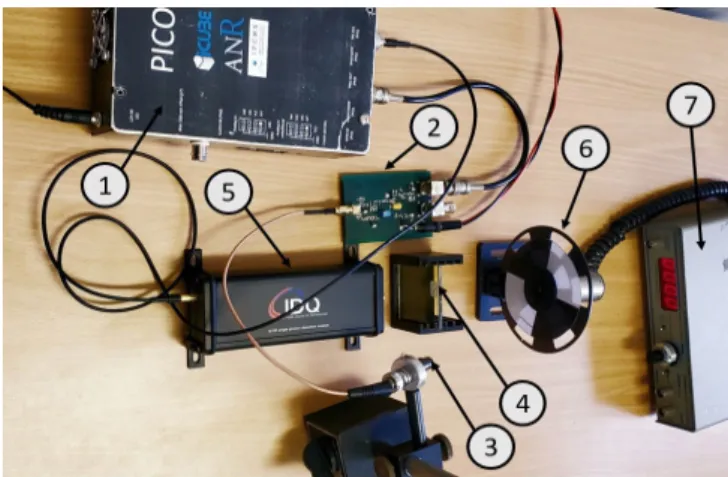
Fig. 5. Experimental set-up. 1- SoC FPGA platform withpower supply,2- Pulsed laser driver, 3- Laser diode with collimating lens, 4- 480 nm high pass optical filter, 5- SPAD, 6- Optical Chooper used to simulate the droplets flow, 7- Chooper controlor.
IV. EXPERIMENTAL RESULTS
A. Experimental setup
This system was implemented using a low cost SoC FPGA platform, namely the “Altera DE-10 Nano” kit. As a pulsed light source, a 450 nm, 50 mW CW laser diode is driven by a fast pulse generator described in [10]. The laser diode is mounted on an optical lens system to collimate the beam. For the photon detection, an ID100 commercial SPAD from IDQ is used and coupled with an optical 480 nm high pass filter. In order to test our system, the droplet-background sequence was emulated using some white paper segments separated by non-fluorescent dark parts. The set rotates at a constant speed thanks to a rotating disc acting as an optical chopper. The droplets’ sizes are defined by the segment width, while the flow rate is determined by the chopper’s rotation rate; the droplet flow rate is calculated by multiplying the number of paper segments by the motor rotation rate. Fig. 5 presents the system set-up. Most of the system’s parts cost less than 200$ each except for the commercial SPAD.
B. Experimental results discussion
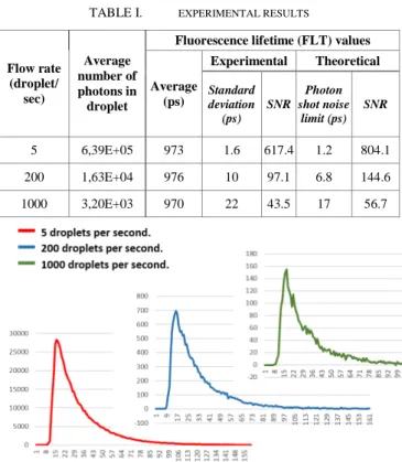
In order to evaluate the system performance, extensive experimental tests were performed at different flow rates and with droplets of different sizes. The obtained results showed that the system was able to detect all the emulated droplets without reporting any missed droplet. Since all the droplets have the same FLT because they are made of the same material, the measured FLT values has a standard deviation close to the theoretical quantum photon shot noise limit, even for a low number of photons in droplet. Table I shows the experimental results for three emulated flow rates, whereas Fig. 6 shows the droplet histogram at these flow rates. The obtained results show that even at a high flow rate of 1000 droplet per second, the signal to noise ratio remains above 40 allowing efficient screening as explained in [8].
TABLE I. EXPERIMENTAL RESULTS
Flow rate (droplet/ sec) Average number of photons in droplet
Fluorescence lifetime (FLT) values
Average (ps) Experimental Theoretical Standard deviation (ps) SNR Photon shot noise limit (ps) SNR 5 6,39E+05 973 1.6 617.4 1.2 804.1 200 1,63E+04 976 10 97.1 6.8 144.6 1000 3,20E+03 970 22 43.5 17 56.7 V. CONCLUSION
In this work, we have presented a FLT measurement system for real-time high-throughput microfluidic droplet sorting. We have described the global structure of this system and introduced the packetizing notion, which provides a robust approach for droplet detection. We have tested this system on an emulated droplet flow at different rates (up to one thousand droplets per second) and with different droplet sizes. The system detected the droplets and measured their FLT. The standard deviation of the measured FLT values is only 30% above the theoretical quantum photon shot noise limit. This system paves the way to FLT droplet sorting in high-throughput condition with microfluidic.
ACKNOWLEDGMENT
The authors would like to thank the French National Research Agency (ANR-15-CE11-0006) and the European Interreg WPS Project for funding this study.
REFERENCES
[1] O. J. Miller et al., “High-resolution dose-response screening using droplet-based microfluidics,” Proc Natl Acad Sci U S A. 2012 Jan 10;109(2):378-83. doi: 10.1073/pnas.1113324109.
[2] J. C. Baret et al., ”Fluorescence-activated droplet sorting (FADS): efficient microfluidic cell sorting based on enzymatic activity,” Lab Chip. 2009 Jul 7;9(13):1850-8. doi: 10.1039/b902504a.
[3] P. I. Bastiaens and A. Squire, “Fluorescence lifetime imaging microscopy: spatial resolution of biochemical processes in the cell,” Trends Cell Biol. 1999 Feb;9(2):48-52.
[4] D. M. Gakamsky, R. B. Dennis, S. D. Smith, “ Use of fluorescence lifetime technology to provide efficient protection from false hits in screening applications,” Anal Biochem. 2011 Feb 1;409(1):89-97. [5] S. Pritz et al., “A fluorescence lifetime-based assay for abelson kinase.”
J Biomol Screen. 2011;16(1):65-72. doi: 10.1177/1087057110385817. [6] R. L. Cornea et al., “High-throughput FRET assay yields allosteric SERCA activators,” J Biomol Screen. 2013 Jan;18(1):97-107. doi: 10.1177/1087057112456878.
[7] P. Hansson et al., “A Comparative Study of Fluorescence Assays in Screening for BRD4,” ASSAY and Drug Development Technologies.Oct 2018.372-383.http://doi.org/10.1089/adt.2018.850 [8] J. Léonard et al. , “High-throughput time-correlated single photon
counting.” Lab Chip. 2014 Nov 21;14(22):4338-43. doi: 10.1039/c4lc00780h.
[9] S. Hasan et al., “Fluorescence lifetime-activated droplet sorting in microfluidic chip systems,” Lab Chip, 2019,19, 403-409, DOI: 10.1039/c8lc01278d.
[10] W. Uhring, C. Zint and J. Bartringer, "A low-cost high-repetition-rate picosecond laser diode pulse generator" Proc. SPIE 5452 Semiconductor Lasers and Laser Dynamics vol. 583 September 2004, doi.org/10.1117/12.545038.
[11] I. Malass, W. Uhring, J. P. Le Normand, N. Dumas and F. Dadouche, “ Parallelized integrated time correlated photon counting system for high photon counting rate applications,” Photon Counting, Nikolay Britun (Eds.), Chapter. 9, pp 209-224, InTech, march 2018. ISBN: 978-953-51-5775-5, doi:10.5772/intechopen.72273
[12] F. Dadouche et al., “New design-methodology of high-performance TDC on a low cost FPGA targets,” Sensors & Transducers Journal, IFSA Publishing, pp 123-134, Vol. 193, n° 10, 2015
[13] T. Lieske, W. Uhring, N. Dumas, J. Leonard and D. Fey, "Embedded fluorescence lifetime determination for high throughput real-time droplet sorting with microfluidics," 2017 Conference on Design and Architectures for Signal and Image Processing (DASIP), Dresden, 2017, pp. 1-6. DOI: 10.1109/DASIP.2017.8122129.
[14] Intel Corporation. (2019b). Modular Scatter-Gather DMA core. In ORG. Intel Corporation (Ed.), Embedded peripherals IP User Guide (pp. 322–371). Retrieved August 26, 2019.
[15] D. Tyndall, et al., “A high-throughput time-resolved mini-silicon photomultiplier with embedded fluorescence lifetime estimation in 0.13 µm CMOS,” IEEE Transactions on Biomedical Circuits and Systems, 6(6), 562–570. 2012, doi:10.1109/tbcas.2012.2222639 Fig. 6. Droplet final histogram for different flow rates. Horizontal axis: