HAL Id: hal-02003218
https://hal.archives-ouvertes.fr/hal-02003218
Submitted on 1 Feb 2019HAL is a multi-disciplinary open access archive for the deposit and dissemination of sci-entific research documents, whether they are pub-lished or not. The documents may come from teaching and research institutions in France or abroad, or from public or private research centers.
L’archive ouverte pluridisciplinaire HAL, est destinée au dépôt et à la diffusion de documents scientifiques de niveau recherche, publiés ou non, émanant des établissements d’enseignement et de recherche français ou étrangers, des laboratoires publics ou privés.
Hydrothermally enhanced magnetization at the center of
the Haughton impact structure?
William Zylberman, Yoann Quesnel, Pierre Rochette, Gordon R. Osinski,
Cassandra Marion, Jerome Gattacceca
To cite this version:
William Zylberman, Yoann Quesnel, Pierre Rochette, Gordon R. Osinski, Cassandra Marion, et al.. Hydrothermally enhanced magnetization at the center of the Haughton impact structure?. Meteoritics and Planetary Science, Wiley, 2017, 52 (10), pp.2147-2165. �10.1111/maps.12917�. �hal-02003218�
Hydrothermally-enhanced magnetization at the center of the Haughton impact
structure?
Zylberman W.
1, 2, Quesnel Y.
1, Rochette P.
1, Osinski G. R.
2, 3, Marion C.
2, Gattacceca J.
11Aix-Marseille Univ, CNRS, IRD, Coll de France, CEREGE UM34, Aix-en-Provence, France
2University of Western Ontario, Centre for Planetary Science and Exploration and Dept. Earth Sciences, London, ON, N6A
5B7, Canada
3University of Western Ontario, Dept. Physics and Astronomy, London, ON, N6A 5B7, Canada *Corresponding author:[email protected]or[email protected]
Abstract–Haughton is a ~24 Myr old mid-size (apparent diameter 23 km) complex impact structure
located on Devon Island in Nunavut, Canada. The center of the structure shows a negative gravity anomaly of -12 mgal coupled to a localized positive magnetic field anomaly of ~900 nT. A field expedition in 2013 led to the acquisition of new ground magnetic field mapping and electrical resistivity datasets, as well as the first subsurface drill cores down to 13 m depth at the top of the magnetic field anomaly. Petrography, rock magnetic and petrophysical measurements were performed on the cores and revealed two different types of clast-rich polymict impactites: (1) a white hydrothermally-altered impact breccia, not previously observed at Haughton, and (2) a grey impact breccia with no macroscopic sign of alteration. In the altered core, gypsum is present in macroscopic veins and in the form of intergranular selenite associated with colored and zoned carbonate clasts. This altered core has a natural remanent magnetization (NRM) four to five times higher than materials from the other core but the same magnetic susceptibility. Their magnetization is still higher than the surrounding crater-fill impact melt rocks. X-ray Fluorescence data indicate a similar proportion of iron-rich phases in both cores and an enrichment in silicates within the altered core. In addition, alternating-field demagnetization results show that one main process remagnetized the rocks. These results support the hypothesis that intense and possibly localized post-impact hydrothermal alteration enhanced the magnetization of the clast-rich impact melt rocks by crystallization of magnetite within the center of the Haughton impact structure. Subsequent erosion was followed by in-situ concentration in the subsurface leading to large magnetic gradient on surface.
INTRODUCTION
Hypervelocity impact craters, or impact structures when eroded, are one of the most common and yet little understood geological landforms at the surface of solid planetary objects (Osinski and Pierazzo 2013). They form as a result of the impact of an asteroid or comet traveling at cosmic velocity with the solid surface of a planet or another celestial body (e.g., Grieve 1987; Melosh 1989). Today, an increasing number of high-resolution spatial and spectral datasets are available for planetary bodies such as the Moon and Mars, which can be used to identify their surface mineralogy (e.g., Bibring et al. 2006) and/or to study deposits associated with impact craters (Wöhler et al. 2014). Such remote sensing studies are now well-constrained by data collected by the rovers and landers (e.g., Squyres et al. 2004; Coustenis et al. 2007; Grotzinger et al. 2014; Auster et al. 2015). Together, these orbital and in situ studies have revealed how impact-generated hydrothermal alteration is a widespread process on Mars (e.g., Rathbun and Squyres 2002; Marzo et al. 2010) and Earth (Newsom et al. 1986; Osinski et al. 2013; see Pirajno 2009 for a general review on hydrothermal alteration and processes) and how impacts are of primary importance in interpreting the geophysical signature of planetary surfaces (Acuna et al. 1999; Wieczorek et al. 2013; Zuber et al. 2013).
Ground-truth of such observations coming from investigations of impact structures on Earth (e.g., Osinski et al. 2005a) is needed to correctly assess and interpret these data. However, the internal structures of terrestrial complex impact craters are often poorly constrained, mainly due to a lack of data: usually only one geophysical campaign (often aeromagnetics, sometimes with ground gravity
measurements) has been carried out over most structures to quickly reveal their overall signature (e.g., Pilkington and Grieve 1992). This prevents a detailed understanding of the nature and geometry of the sources of local geophysical anomalies, such as possible hydrothermally-altered geological formations and how exactly hydrothermal systems form and evolve within central uplifts.
One of the best-preserved complex impact structures on Earth is the Haughton impact structure (Fig. 1), located on Devon Island in the Canadian High Arctic Archipelago (75°22’N, 89°41’W), with a ~23 km apparent crater diameter (Osinski and Spray 2005). Various ages have been proposed for the Haughton impact (Omar et al. 1987; Jessberger 1988; Sherlock et al. 2005), with the most recent study suggesting that it was formed at 23.5 ± 2 Ma (Young et al. 2013). The pre-impact target is composed of the Lower Paleozoic sequence of the Arctic Platform (Cambrian, Ordovician and Silurian sediments about 2 km thick) overlying Precambrian metamorphic basement rocks of the Canadian Shield. It is mainly limestones and dolostones, with minor evaporites, shales and sandstones. The crystalline basement is composed of granitic and tonalitic gneisses of granulite facies intercalated with metasedimentary rocks (Osinski et al. 2005a). These gneisses are intruded by a series of charnokitic plutons at ~1.9 Ga, and later Sinian (~600–800 Ma) brown to black, massive dikes of weathered dolerite intrude all the pre-Paleozoic rocks and the overlying sedimentary rocks (Thorsteinsson and Mayr 1987).
The impact produced a layer of clast-rich impact melt rocks (Fig. 1) that contain a groundmass of microcrystalline carbonate intermingled, but not mixed, with Si-Al-Mg silicate glass (Osinski and Spray 2001; Osinski et al. 2005b). This hot impact melt layer interacted with surface waters to create a hydrothermal system which cooled during several tens of thousands of years (Osinski et al. 2005c; Parnell et al. 2005), generating hydrothermal alteration of impact melt rocks in the central part of the structure and localized hydrothermal pipes in concentric fault systems (Osinski et al. 2001). Other locations around the structure also show localized hydrothermal mineralization of quartz, calcite, marcasite, pyrite, celestite, barite and fluorite in the form of vugs and veins (Osinski et al. 2005c). Rock magnetism experiments have shown that pyrrhotite is the main carrier of the remanent magnetization in the Paleozoic sedimentary target rocks while magnetite (and/or maghemite) can be the carrier of the magnetization in crystalline clasts found nearby the center (Quesnel et al. 2013). However, no evidence for a hydrothermal origin of those minerals has been documented to date.
Haughton possesses a negative Bouguer gravity anomaly 24 km in diameter (Pohl et al. 1988) and a local minimum at the crater center of approximately -12 mGal (Glass et al. 2012). Pohl et al. (1988) also detected a positive magnetic anomaly with a local maximum of 700 nT near the crater center (named “Anomaly Hill”), corresponding to the minimum of the gravity anomaly. These authors suggested an identical source for both anomalies. They modeled the magnetic anomaly with a simple cone-shape model of low-density material magnetized at 1.3 A m-1 and a 1 km deep root. They
suggested the source of both anomalies was a strongly compressed and sheared core of porous material originating from sedimentary and/or metamorphic target rocks. The interpretation was that these rocks underwent large degassing increasing the porosity and acquired a coherent thermoremanent magnetization (TRM) when cooling in the Earth’s magnetic field (Pohl et al. 1988). Other authors (Robertson and Sweeney 1983) did not exclude normal magnetic contrast with the basement or shock remanent magnetization (SRM; e.g., Gattacceca et al. 2010).
More recent studies delivered additional data covering the whole crater (Glass et al. 2012) but no detailed modeling of the central magnetic anomaly was done until 2010 when a field expedition was conducted in order to acquire detailed data of the magnetic field anomaly (Quesnel et al. 2013). This new ground magnetic survey found the peak of the magnetic anomaly at 424677.09E, 8367951.27N (UTM Zone 16 projection with NAD83 datum). Results indicate a 900 nT maximum amplitude and a 1.2 km wide magnetic field anomaly while the surroundings show a negative signal down to -100 nT. The maximum of the ground anomaly corresponds to a local 20 nT m-1gradient,
indicating that some parts of the main magnetized source may have reached the subsurface. Further numerical modeling of the magnetized source shows that a magnetization contrast of ~1.5 A m-1is
necessary to account for the anomaly, with the shallowest parts (<30 m) having a higher magnetization of ~2.3 A m-1(Quesnel et al. 2013). The study also shows that no target rocks at Haughton have total
magnetizations strong enough to explain the anomaly except a small fraction (4%) of unusual basement rocks, but the high density of these samples is incompatible with the gravity anomaly.
Therefore, it was proposed that impact-induced hydrothermal alteration enhanced the magnetization of highly porous uplifted basement rocks (Quesnel et al. 2013), but that this material was not available at known outcrops.
In this paper, we correlate new field and laboratory geophysical data to petrography of the first near surface (<15 m depth) drill cores within the central uplift of the Haughton impact structure, to ground the above hypothesis.
METHODS
Drilling
Fieldwork conducted in 2010 suggested that the superficial part of the source of the central magnetic anomaly at Haughton may be shallow enough (<30 m) to be drilled (Quesnel et al. 2013). In 2013, three drill holes located near the center of the crater (Fig.1) and named F1, F2 and F3 (Fig. 2), were conducted using a light drilling equipment (JKS Packsack from Partshq, Canada) equipped to recover 2.5 cm diameter cores. Recovery rate was low (0% for F1, ~25% for F2, and ~10% for F3, not including cuttings) because of the thickness of surficial unconsolidated material loosened by permafrost formation, and melting of permafrost during drilling operations. Solid drill cores were recovered in F2 starting at a depth of -8.6 m under the surface (~110.5 m real altitude) until the end of the drill hole at -12.7 m (corresponding to a cumulated length of 3.2 m without gaps), and in F3 starting at a depth of -2.9 m (~116.1 m real altitude) down to -4.9 m (corresponding to a cumulated length of 0.4 m without gaps). The sections without satisfactory recovery yield rock fragments that were partly drilled during advancement and partly loose sand and gravel material falling from the hole above. Full details on the depth of recovered material is presented in the Supplementary Material (Figure S1).
Field geophysics
New high resolution mapping of the vertical gradient of the magnetic field was used to locate precisely the peak of the anomaly and to plan the drilling locations in zones with different magnetic signatures (red polygon in Fig. 2). Borehole logging of the vertical gradient of the magnetic field as well as electrical resistivity tomography (ERT) were used to correlate the material recovered in the drillings to physical properties of the subsurface. The equipment used for mapping the vertical gradient of the magnetic field was a field gradiometer Foerster Ferex 4.032 API. The red polygon area (Fig. 2 and Fig. 4a) was mapped with a 10 to 5 m line-spacing. We also mapped the gradient with a higher resolution of 1 m line-spacing over the drill site (Fig. 4b).
ERT was performed using an ABEM Terrameter SAS 64-4000 with a Wenner-Schlumberger protocol. Ten ERT profiles were collected at the top of the positive magnetic anomaly (Fig. 2). Profile n°10 is a W-E profile realized apart from the anomaly zone in order to give the “normal” signature of the permafrost. Each profile was 63 m-long with a spacing of 1 m, giving access to about 8 meters depth. The datasets were processed using the resistivity imaging software RES2DINV (Geotomo Software).
Rock magnetism
A MS2C Bartington Core Logging Sensor susceptibility meter was used to measure the volumetric magnetic susceptibility of the cores (noted K, in 10-5 SI). For the measurements and
alternating-field (AF) demagnetizations of natural remanent magnetizations (NRM) and anhysteretic remanent magnetizations (ARM), a superconducting quantum interference devices (SQUID) 760R magnetometer with a sensitivity of 2×10-12A m² of 2G Entreprises was used. Continuous cores were
measured directly in the magnetometer and cuttings were measured as discrete samples. The inclination (I) is the inclination of the bulk NRM measured by the SQUID magnetometer. The median destructive field (MDF) – i.e. the value of the demagnetizing field for which the remanence is reduced by 50% – is calculated for the ARM and NRM, in order to observe the variations of coercivity through
the cores. We also used a MicroMag 3900 Vibrating Sample Magnetometer (Princeton Measurements Corp.) to determine the magnetic mineralogy. It has a sensitivity of 5×10⁻⁹ A m² and allows
measurements at room temperatures of first magnetization curves, hysteresis cycles and remanence curves. We calculate ratios of the saturation remanent magnetization (Mrs) to the saturation
magnetization (Ms) as well as remanent coercivity (Bcr) to the coercivity (Bc). The MFK1
susceptibility meter with CS3 furnace from AGICO was also used to confirm the magnetic mineralogy with thermomagnetic curves. All magnetic measurements were performed at CEREGE.
Petrophysics
Bulk densities (BD) were calculated based on the measurements of diameter (d), height (H) (with a ruler and a caliper) and mass (m) of small cylinders obtained after sawing portions of the drill cores. In order to have a precise result, the volume was calculated using the average value of a matrix constituted of 8 values resulting from a combination between the length of the cylinder (measured 4 times) and the diameter (measured 2 times). The mass was measured with a high-precision balance. The second step was to measure grain densities (GD) (i.e., the density that takes into account the solid volume Vs, which is the volume occupied only by solid grains within the sample once the air has been
removed from its porosity) using the helium pycnometry technique. For this purpose, we used a Stereopycnometer from Quantachrome Instruments. The porosity (φ) is calculated as .
Petrography
A detailed macroscopic petrographic description of the cores was conducted by visual inspection and a ×10 hand lens. We estimated the proportions of components (vol %) in the cores (Table S2 of the Supplementary Material). These estimations were based on the charts of Folk (1951) and Reid (1985). The average grain size (AGS) was calculated based on the measure of the major axis of the five largest clasts. The roundness and sphericity ratio (r/s) was estimated based on Krumbein and Sloss (1956). The sorting index (S) was evaluated based on Stow (2005; modified after Compton 1962). The indicated value is the estimated standard deviation in φ units. For both the AGS and S, the matrix was not taken into account. For the componentry analysis and proportion estimates, the matrix was defined as all components with a diameter <2 mm. Therefore, it not only comprises microscopic phases, but also small clasts visible macroscopically.
Microanalysis
Microanalysis of polished thin sections was performed on the JEOL JXA-8530F Field Emission Electron Probe Microanalyzer at the Earth and Planetary Materials Analysis Laboratory, University of Western Ontario. Element maps were constructed with a step size of 1 µm and a dwell time of 15 ms. Wavelength dispersive spectrometry (WDS) was used to map Mg, Ti, Mn, and Fe with standards enstatite, rutile, rhodonite and hematite, respectively. Energy dispersive spectrometry (EDS) was used to map Ca, Ni, S, Cr, Al and Si. Element maps, spectrometry and backscatter electron (BSE) imaging were collected with the probe current set to 15 kV and 25 nA. X-ray fluorescence (XRF) measurements were performed on sections of the cores using a portable instrument from Bruker (Tracer IV-SD).
RESULTS
Field Geophysics
Electrical resistivity tomography
ERT profile n°1 comprises the three drill holes (Figs. 2 and 3) and shows most of the features observed on all the other ERT profiles. Therefore only this profile is analyzed here (see Supplementary Material for the other ERT cross-sections). Four resistivity domains are observed on
ERT01: (1) a subsurface low-resistivity horizontal zone (LRHZ) following the topography, which has a ~1–1.5 m deep base and is characterized by resistivity values of ~25–250 Ω m; (2) an intermediate-resistivity zone (IRZ), characterized by intermediate-resistivity values of ~600–3000 Ω m, is found generally below the LRHZ and extends downward in some locations; (3) a high-resistivity zone (HRZ), characterized by resistivity values ≥3000 Ω m, composes the surroundings of the (4) LRA, a low-resistivity anomaly in the permafrost characterized by resistivity values of ~10–600 Ω m. A local minimum ≤100 Ω m is detected at a depth of -4.5 m corresponding to a real altitude of ~114.5 m at the end of drilling F1.
Vertical gradient of the magnetic field
Figure 4a shows a low-resolution map of the vertical gradient. It reveals positive anomalies of ~20–30 nT m-1while the surroundings show a weak negative signal of 0 to -5 nT m-1. Drilling site F3
is located in this “quiet” zone; whereas F1 and particularly F2 are in the large gradient area. Other isolated anomalies of very weak intensities are detected farther out, but may be related to the noise induced by the mapping conditions (small movements of the gradiometer due to the wind and/or topography and/or walking).
Figure 4b corresponds to the high-resolution map over the drilling site. An ice-wedge polygon is observed in the field of this area (small black dashed lines in Fig. 2). Its borders are exactly aligned with a magnetic contrast leading to a negative gradient of ~0 to -20 nT m-1. A signal of ~20–25 nT m-1
was measured over F1, ~30–35 nT m-1 over F2, and ~0 to -5 nT m-1 over F3. In addition to the
mapping of the vertical gradient of the magnetic field, a log of the same gradient was conducted through the borehole F2 from the surface to 8 m depth (Fig. 4c). It shows large gradients, specifically around -4.5 m, reaching several hundreds of nT m-1.
A positive correlation was observed between low resistivity values (~100–600 Ω m) and high vertical magnetic field gradient (~20–30 nT m-1). The correlation is the best at the center of ERT01
apparent resistivity model where the magnetic anomaly is the highest (Figs. 4b and 4c), that is at a distance ~23<d<~36 meters on ERT01 (Fig. 3). In this zone, both magnetic and resistivity anomalies can be decomposed in two peaks where the anomalies are maximum. The comparison between the ERT model (Fig. 3) and the magnetic field gradient log (Fig. 4c) also indicates a correlation between the LRA minimum (≤100 Ω m) and the high magnetic field gradient inside the F2 bore hole (-400 nT m-1): these two anomalies are located at the exact same depth, approximately -4.5 m, suggesting a
similar source for both anomalies. This depth corresponds to the Quaternary sand and gravel layer inferred from the drilling.
Petrography of the Drill Cores
Two main types of lithologies were recovered from the drillings. The F2 drill core is a white polymict impact breccia with abundant rounded clasts and widespread alteration (Figs. 5a, b, c, e, f), whereas the F3 drill core is a grey polymict impact breccia with abundant angular clasts and no macroscopically visible alteration (Fig. 5d). Intense microscopic alteration has been identified in F2 by Marion et al. (2016a), wherein silicate clasts and rims have altered to clay minerals. Both types are non-stratified and classified here into the clast-rich category following the classification of Osinski et al. (2008), as both contain generally high amounts of clasts (2% to 80 % locally, 30 % average). F3 shows a fragmental texture, but whether F2 has a melt or fragmental matrix is not clear since secondary alteration textures are superimposed on the primary textures. However, important variations are observed in the texture as well as in the amount of clasts.
Matrix
Macroscopically, the matrix of the impact breccias is white in F2 (Figs. 5a–c) and grey in F3 (Fig. 5d). It is composed of different components such as clasts with diameter <2 mm, ranging from partially altered to fresh, and various matrix phases (gypsum in veins and intergranular, microscopic phases) (Fig. 5a). In F2, the matrix proportion is in general high (up to ~98%; Fig. 5c) but sometimes decreases dramatically in coarse-grained zones (e.g., ~20 % in coarse-grained zone of Fig. 5b), with an
average of ~66 %. In F3, no variation is observed (<5 %) and the average matrix proportion is ~80 % (Table S2 of the Supplementary Material; Fig. 5d).
Clasts
Carbonates are the most common type of clasts encountered in the drill cores, representing in general more than 90 % of all the clasts. Within F2, the clasts are often zoned and/or oxidized (Figs. 5e, f) and have a roundness/sphericity ratio (r/s) of 0.8/0.8 (high roundness and sphericity; Krumbein and Sloss 1956) even if some lithologies are more angular with sometimes rectangular shapes. They can have different colors (white, dark or light grey) and sometimes show internal structures (e.g., sedimentary beds). Within F3, no zoning and/or oxidation are observed. The carbonate clasts within F3 are more angular with a lower roundness/sphericity ratio of 0.4/0.8. Carbonates are also the largest clasts found in the cores (~5.5 cm maximum). Other types of clasts include black, grey or dark-brown mafic angular clasts, metagranite and gneiss clasts, and translucent “vitric” clasts. For full detail on the different kinds of clasts, componentry estimates and petrographic description, see the Supplementary Material.
Alteration
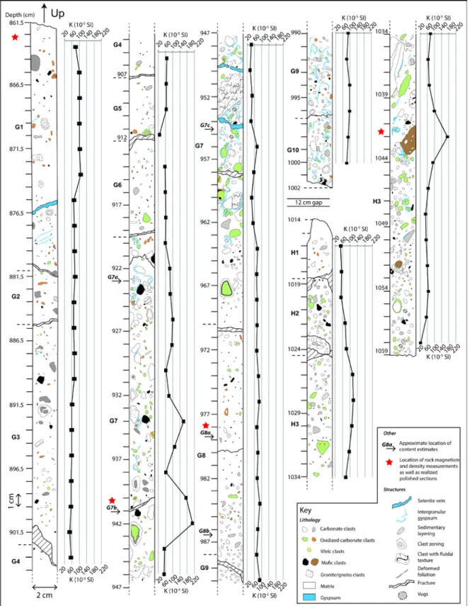
The core F2 has specific structures that are not found in the core F3 and in samples from the surface. For example, cm-size gypsum veins (selenite variety) were observed macroscopically within the core F2. The veins are generally composed of a single phase of transparent and colorless gypsum (e.g., Fig. 5b, label 1). Zoning within clasts is widespread and found throughout the core F2. It includes symmetric zoning (Fig. 5e, examples A and B) and asymmetric zoning (Fig. 5e, example C). Macroscopically, the zoning is only found within carbonate clasts. It is often associated with green and/or orange colors (called “alteration colors” in the rest of the paper) within carbonate clasts, in association with parts of the core containing visible gypsum (e.g., section F2 G7). As can be seen in the core log (Fig. 6), the proportion of the green alteration color increases in zones containing visible gypsum. In addition, such grains often contain dark or black zones, which can be microscopic iron-bearing minerals. These green and orange alteration colors are not observed in the F3 core and within rocks sampled at the surface (Osinski et al. 2005b; Quesnel et al. 2013) – they are exclusive to drill core F2. There is sometimes a relation between zoning and alteration colors (Fig. 5f, examples C, D, H). Other evidences for hydrothermal alteration include small vugs within coarse-grained zones associated to geodes of carbonate (~5 mm).
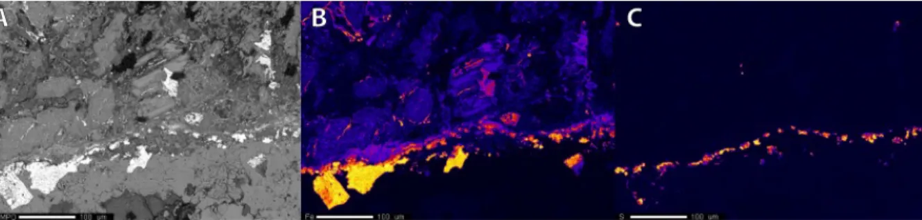
EPMA analysis shows that a rim of Fe-oxides and sulfides occurs around a dolerite clast (Fig. 7) within the core at the F2G7b location (Fig. 6). The composition of the magnetites of the rim (secondary magnetites) is different from the magnetites within the dolerite clast (primary magnetites), which are enriched in Ti and Mn and show a skeletal texture while the magnetites of the rim are porous and often associated to smaller crystals of euhedral pyrite. Sometimes, a second generation of smaller, euhedral and non-porous magnetites are found around the larger first generation crystals.
The results of the XRF measurements (Figure S2, Supplementary Material) show that F2 and F3 have similar contents in Fe and Ti, but that F2 is enriched in S, Si, Mg and slightly in Ba, while F3 is enriched in Ca and Sr, relatively. More details on the petrography of the cores – especially concerning microscopic phases – can be found in a recent abstract from Marion et al. (2016a).
Changes with depth
The evolution with depth of the lithological facies and magnetic susceptibility of the cores is shown on the geological and geophysical logs (Fig. 6). The section F2 G1 to H3 presented here is where most variation in petrography (grain-size, components) and magnetic properties (susceptibility, NRM) are observed.
The F2 core is not stratified but shows important grain-size variations alternating between fine-grained zones (Fig. 5c; G1–G6, G8, H1 on Fig. 6) and coarse-fine-grained zones (Figs. 5a, b; G7, G9, G10,
H2, H3 on Fig. 6). The evolution of the F2 lithology with depth (Fig. 6) is cyclic: it starts with a very fine-grained part (G1–G6) where almost no intergranular gypsum is found, as well as very few green alteration colors. It then becomes coarse-grained in section G7 and fine-grained again in section G8. Subsequently, it is coarse-grained from section G9 to H3. These changes in grain-size are often very sharp and take place within a few centimeters (e.g., G6–G7, d=919 cm).
In comparison, F3 is homogenous (fine-grained) and shows no important grain-size variations. In addition to the color, the main differences between F2 and F3 are the widespread alteration (zoning, gypsum, and alteration colors), the higher r/s ratio, coarser grain-size and worst sorting of F2 (Supplementary Material). Zoning and alteration colors within F2 are correlated to the presence of gypsum, both in veins and intergranular (e.g., G7 at d=959 cm and H3 at d=1044 cm). Tables S1 and S2 of the Supplementary Material provide a summary of the main petrographic characteristics of the cores.
Density and porosity
We measured the bulk and grain densities, as well as the porosity of eight cylinders from F2 and 2 cylinders from F3 as well as an angular sample of impact-melt rock from the surface (sample 40-7) (Table 1). F2 and F3 show similar bulk densities, on average 1.76. The average grain density of the samples is 2.51, indicating an average porosity of 29 %. An important result is the difference in grain densities and porosities between F2 and F3. F2 is characterized by an average grain density of 2.43 associated with an average porosity of 28 %. F3 has a grain density of 2.70 that is the same as sample 40-7 – which is a grey impact melt rock from the surface – and a porosity of 34 % also higher than F2.
The grain density of the grey impact melt rock (2.70) corresponds to the density of calcite; whereas the grain density of the white impact melt rock (2.43) is closer to the density of gypsum (~2.30) and clays, thus indicating a mineralogy dominated by sulfates and clays with probably fewer calcite. Such an interpretation is coherent with the values of the porosity, as a lower porosity in F2 could be explained by the abundance of intergranular gypsum and clays as observed in coarse-grained zones (Figs. 5 and 6).
Magnetic properties
The average and median magnetic susceptibilities are similar for F2 and F3 (Table 2) with values of ~77 10-5SI. However, the field geophysical results (Figs. 3 and 4) have shown that F2 and
F3 are in zones with different magnetic (and electrical) signals. Indeed, the difference comes from the NRM of the cores (Table 2), since F2 has an average NRM ~5 times higher than F3 (0.2 A/m for F2 and 0.04 A/m for F3). Also the maximum susceptibilities and NRM are 3 and 13 times higher in F2, respectively. This difference is confirmed in the measurements of the cuttings (Table 3).
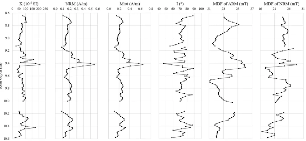
Firstly, the volumetric magnetic susceptibility (K) is correlated to the geological log (Fig. 6): local peaks in the signal are observed in section G7 at depths of 934 cm (K=161 10-5SI and NRM=0.3
A/m) and 942 cm (K=210 10-5SI and NRM=0.6 A/m), as well as in H3 at a depth of 1042 cm (K=174
10-5SI and NRM=0.2 A/m). These peaks are linked to the presence of mafic clasts in
hydrothermally-altered zones (Fig. 6). No peak is associated with other clasts of this nature and similar apparent size in zones where gypsum is not visible (e.g., G2, d=889.5 cm). In addition, gypsum itself cannot be responsible for the peak as gypsum veins are associated to magnetic lows (e.g., G1, d=875.5 cm).
Secondly, a positive correlation is established between the NRM and the magnetic susceptibility (Fig. 8). A relatively stable signal (~60 10-5SI) is observed from the core sections G1 to
G5. Then, a more disturbed signal (~60-200 10-5SI) is encountered from G7–H3 with a maximum at
9.42 m. The signal is characterized by abrupt variations (peaks) visible in all logs but best observable in the inclination data. The average inclination (I) of the NRM is similar in both cores (Table 2) and confirms the direction previously recorded in clasts from the impact melt rocks (I=71°; Quesnel et al.
2013). There are no constraints on the rotation of the cores during the drilling operation, so the declination cannot be used here.
If the difference between F2 and F3 is important, it should also be noted that the magnetization of F3 is still significantly higher than the NRM of basement samples collected on the surface which have a total magnetization intensity weaker than 0.01 A/m (Quesnel et al. 2013). In addition, five surface samples of grey impact melt rock 1-2 km away from the crater center were measured in order to compare with the F2 and F3 cores. These samples of similar aspect (grey color, fragmental texture) than F3, yielded an average NRM of 7.7×10⁻³± 6.8×10⁻³A/m, a value five times
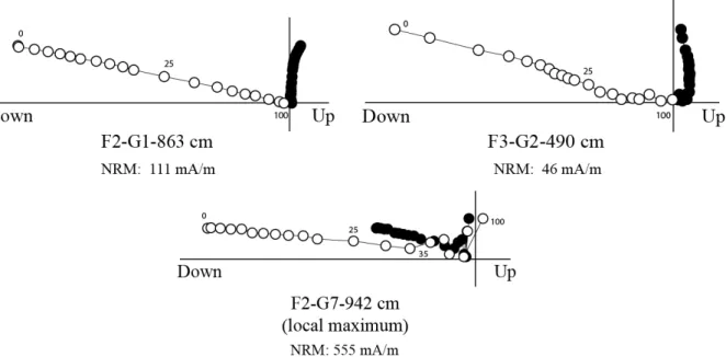
smaller than the NRM of F3 (Table 2). AF demagnetization of the matrix of the cores (Fig. 9) revealed a well-defined, single-component paleomagnetic direction at all depths, both in F2 and F3, whereas some data points correlated to mafic clasts (e.g., F2G7 at d=942 cm visible on Figs. 6 and 8) show chaotic demagnetization above 35 mT (F2-G7-942 cm on Fig. 9).
Hysteresis measurements (Supplementary Material, Table S4 and Fig. S5) gave the following ratios for F2: 0.11<Mrs/Ms<0.31 and 1.81< Bcr/Bc<2.46. Those results are complemented by the MDF
of the ARM (MDFARM), for which all values are comprised between 21 and 26 mT for the core F2G1–
H3 with both average and median values equal to 23 mT (Fig.8). The results are similar in F3 samples (2.05< Bcr/Bc <2.28 and 0.14<Mrs/Ms<0.31) while the MDFARMis slightly higher with an average of
~31 mT. Thermomagnetic curves show inflexions around 580 °C and 500 °C (Supplementary Material, Fig. S4).
DISCUSSION
Alteration
It seems that most of the macroscopic differences between cores F2 and F3 can be attributed to alteration. For example, the higher r/s ratio in F2 (0.5/0.6) compared to F3 (0.3/0.5, Table S1 in the Supplementary Material) appears to be due to the development of alteration haloes (zoning) around clasts as well as dissolution/replacement processes (as indicated respectively by vugs and intergranular gypsum; Fig. 6). The lighter color of F2 compared to F3 could be due to metasomatism which can result in a recrystallization of the microcrystalline carbonates, leading to a coarser grain-size of the matrix. This coarser grain size would allow more light to be reflected from the rock, which is demonstrated as a lighter color. It is also common that hydrothermal alteration results in the production of secondary silicate minerals such as clays, sericite, alunite, quartz or carbonates, giving the altered rocks a bleached aspect in comparison to fresher specimens (Schwartz 1959).
The alteration colors observed in the core F2 (orange and green colors within clasts; pinkish and green color of the matrix; Fig. 5b, c, e, f) are dependent on different minerals precipitated as a result of rock-interactions with oxidative/reducing fluids, or transformation of primary iron-bearing minerals into secondary minerals in response to changing environment conditions. For example, the color of iron-bearing rocks can be directly dependent on the oxidation state of Fe (Sánchez-Navas et al. 2008). It is common for granite and carbonates to take on a reddish or orange color due to heating experiments (Dunlop and Özdemir 1997). It is also known that a higher iron content in the form of hematite results in a redder color (Valanciene et al. 2014). However, the alteration colors are only found within the drill core F2, and are not observed in the drill core F3 nor within the rocks sampled at the surface (Osinski et al. 2005b). This means that they are not caused by impact melting processes but rather by post-impact hydrothermal alteration in association with zoning (Fig. 6).
The microscopic observation of a rim of iron sulfides and oxides around a mafic clast (Fig. 7) is interpreted to be evidence for leaching of Fe contained in primary iron oxides within basement clasts and re-precipitation of secondary Fe-oxides and sulfides around the clasts, thereby enhancing the magnetization by creating additional magnetic minerals. This remobilization could be achieved through post-impact processes such as hydrothermal alteration or reaction of the clasts in a hot melt. However, it has been found only in the strongly altered drill core F2, suggesting again its association
with hydrothermal alteration. This process also better explains the high proportion of sulfides in the rim, as sulfur could have been provided by the hydrothermal fluids that formed the abundant gypsum of the drill core F2. Magnetite formation can also occur at relatively low temperatures (e.g., Schwenzer and Kring 2013). In this case, the secondary magnetites are formed during the late-stage of liquid-dominated carbonate-sulfide/iron oxyhydrate mineralization, in combination with the formation of gypsum (e.g., Kirsimäe and Osinski 2013).
The XRF results (Figure S2, Supplementary Material) indicate a higher content in Si and S, as well as a lower content in Ca in F2 compared to F3. This can be interpreted as an enrichment in sulfates and silicates and a depletion in carbonates in F2 compared to F3. These results confirm the pycnometry data, supporting evidence that the alteration visible in F2 caused to a certain extent the replacement of some carbonate phases by gypsum and silicates, as well as possibly anhydrite. This is coherent with the observation of macroscopic gypsum veins and a bleached color in F2, as well as the grain densities of the cores, i.e., close to gypsum in F2 and similar to calcite in F3. The XRF also shows that the proportion of Fe is similar in the matrix of both cores. Therefore, the higher magnetization of F2 cannot be simply explained by a higher concentration in magnetic minerals, supporting again the hydrothermal alteration hypothesis. Future studies focusing on alteration textures and specifically orange and green (oxidation?) colors within the cores could possibly reveal important constraints on the physico-chemical properties of the hydrothermal fluids at Haughton, and possibly also on the temperature of the impact melt rocks. A detailed microscopic study is ongoing (Marion et al. 2016a, 2016b), and should give more insights on the alteration, hydrothermal and melt phases at Haughton.
Geophysics
The paleomagnetic inclination recorded in the cores (I=72° for F2 and I=77° for F3, Table 2) is similar to the inclination recorded in clasts sampled in the impact melt rocks at the surface (I=71°; Quesnel et al. 2013). The average total magnetization (induced plus remanent) in core F2 is higher than in core F3 and samples from the surface: the average signal of F2 remains around five times above F3 (Tables 2 and 3), even when there is no local magnetic high due to mafic clasts (Fig. 6). This higher magnetization could be a TRM acquired during cooling of the impact melt rocks or a CRM acquired during hydrothermal activity by crystallization of new magnetic minerals. This brings the following question: why aren't some mafic clasts associated with a high, positive magnetic maximum when others of identical aspect are? (Fig. 6) It is also interesting to note that mafic clasts such as those in F2 have not been observed macroscopically in F3.
The AF demagnetization data from both cores evidence a single-component of magnetization (Fig. 9), indicating that the whole-rock (including clasts) has been remagnetized through a unique process. For the core F2G1–H3, MDFARM (23 mT in average) indicates that the magnetic mineralogy
is dominated by PSD magnetite. In F3, MDFARMis slightly higher (31 mT in average), indicating that
the PSD magnetite grains are closer to SD grains (Dunlop 1973, 1981). The variations of MDFNRM
through the core F2G1–H3 (Fig. 8) are similar to MDFARM, with a better defined “stable” zone in G1–
G6. However, the MDFNRMis higher in F2 (also 23 mT in average) compared to F3 (9 mT in average),
an opposite trend to MDFARM. This suggests that the magnetizing processes responsible for the NRMs
of F3 and F2 are different, as F3 possesses a magnetization that was “easier” to remove than F2. This may correspond to a lower temperature of acquisition of TRM or CRM in F3, resulting in a lower efficienty of magnetization process, as well as an eventual superimposed VRM for F3 (suggested by the presence of two directional components in the Zijderveld plot of Fig.9)
Thermomagnetic curves (Supplementary Material, Fig. S4) confirm that the magnetic mineralogy is dominated by magnetite, with sometimes slightly substituted titano-magnetites (500°C< Tc<580°C), consistent with the EPMA and XRF studies. Supporting evidence is brought by the
loops as well as the ratios are typical of SD-PSD magnetite grains (Dunlop and Özdemir 1997). This small magnetic grain size may be a result of the porous texture observed in the recrystallized magnetites of the rim, and/or to the small magnetite crystals they are associated with. Such a texture has also been found to be characteristic of a hydrothermal origin for magnetites (Dunlop and Özdemir 1997). Additionally, samples of impact melt rocks from surface outcrops have weaker saturation magnetizations (Ms) than samples from the drill cores (Supplementary Material, Table S4), indicating
an increase in magnetization within the central uplift. This could be due to recrystallization of new magnetic minerals through hydrothermal processes, and/or to a higher concentration of basement clasts in the central uplift. For example, our VSM measurements show that only 2% of mafic clasts are needed in order to account for the Ms in F2. However, Redeker and Stöffler (1988) did not notice a
significant change in the modal proportion of basement clasts with radial range in the crater, therefore supporting the hydrothermal hypothesis in this case.
Geological interpretation
Despite the relatively recent age of the impact at Haughton, this study shows that successive geological processes (central uplift, formation of melt sheet, hydrothermal alteration, erosion and sedimentation) have contributed to the observed geophysical anomalies. The impact-related high pressures may be responsible for SRM and/or TRM acquisition in the subsequently shocked or melted target rocks (Fig. 10a and b). In response to the impact, many of these target rocks became more porous (Singleton et al. 2011). Therefore we propose that a highly porous core of basement material was uplifted and later altered by hot, impact-induced hydrothermal fluids (Fig. 10c.i). At this stage, a CRM can be imparted to the rocks and eventually replace the previous SRM/TRM magnetizations. The CRM can enhance the magnetization through leaching of primary Fe-Ti oxides from basement clasts and re-precipitation of peculiar porous magnetites as rims and eventually within the impact melt rock matrix.
Possibly several millions of years later, this core of uplifted, altered basement rocks was exposed to the surface and eroded (Fig. 10c.ii). Then, post-impact sedimentary processes, in a fluvial or glacial/periglacial environment, concentrated the eroded materials. The near surface (<10 m depth) part of the magnetized source (corresponding to the high magnetic field gradient recorded on surface and to the measured resistivity low, as well as the top magnetic prisms proposed by Quesnel et al.) corresponds perfectly to an epigenetic sand/gravel placer deposit of highly magnetic (≥2.3 A m-1)
basement clasts (references about placer deposits can be found in Jébrak and Marcoux, 2008). No drill core was recovered at this depth but only cuttings and rock fragments with abundant mud. In fact, geological formations with a high conductivity are often highly porous and saturated with water. It can be described in a simplified model of moraine material concentrated below a wet-base ice-sheet, in which the flowing water would progressively dissolve the gypsum of a hydrothermal pipe to create a topographic low in which denser material such as mafic clasts and magnetite grains can accumulate, thus forming “an anomaly at the top of the anomaly” (Fig. 10, c.iii). The NRM directions in the quaternary gravel and sand layer should be randomized by sedimentation, besides a post deposition VRM component. So the total magnetization of that layer is only induced magnetization plus an eventual VRM. The possibility for enhanced VRM could be linked to the concentration of coarse size multidomain magnetite with respect to the bedrock
The observed differences between F2 and F3 and the fact that F3 is still more magnetic than rocks farther from the crater center could be explained by different degrees or types of hydrothermal alteration, or more simply because of the proximity of F3 to the F2 hydrothermal zone, which would have consequently remagnetized F3 without obvious alteration signs (e.g., gypsum veins, zoning). The deeper (~20 m–1 km depth) and main source of the positive magnetic field anomaly is still unknown, but could possibly be explained by a core of uplifted basement rocks hydrothermally remagnetized at ≥1.5 A m-1.
CONCLUSIONS
This study includes the description of several new physical features which have never been described before at Haughton, such as hydrothermally-altered impact breccias and a low-resistivity anomaly coupled to a high magnetic field gradient near the surface. Magnetic measurements coupled to petrographic observations indicate that hydrothermal alteration is responsible for enhancing the magnetic signal of the impact melt rocks by crystallization of magnetic minerals (magnetite), leading to increased magnetic susceptibility, and possible acquisition of CRM. However, the total magnetization of the recovered rocks is lower by a factor of eight than the magnetization of the deep source necessary to account for the magnetic field anomaly. Near surface geophysical anomalies which superimpose to the main magnetic field anomaly are due to post-impact, epigenetic processes such as sedimentation and concentration of magnetic grains on top of the main magnetic source body.
Acknowledgments—We thank the two anonymous reviewers for their detailed and
constructive comments that strongly improved the initial manuscript. IPEV is acknowledged for funding the field work. We are particularly indebted to S. Marguerite and S. Meulé (SETEL/CEREGE) for providing a customized light drilling system, which miraculously worked in this environment (See Figure S3, Supplementary Material). Logistical support from the Polar Continental Shelf Project is gratefully acknowledged. This work has been carried out thanks to the support of the A*MIDEX grant (n°ANR-11-IDEX-0001-02) funded by the French Government "Investissements d'Avenir" program. MITACS and Campus France are thanked for facilitating international collaboration by providing the MITACS Globalink Research Award-Campus France to W. Z. Special thanks goes to Dr. Richard Grieve for sharing his knowledge on impact breccias, to Dr. Livio L. Tornabene for his help with GIS, to Marc Beauchamp for his help with the EPMA, to Dr. Catherine Keller for her help with the XRF, and of course to Dr. François Demory, for his kind advices, patience and supervision in the laboratory of rock magnetism of the CEREGE. Dr. John Mustard and NASA Digital Globe are thanked for sharing the high resolution orbital image over Haughton. Sabrina Muise is personally thanked for her gentle advices and corrections.
Editorial Handling—
REFERENCES
Acuna M. H., Connerney J. E. P., Ness N. F., Lin R. P., Mitchell D., Carlson C. W., McFadden J., Anderson K. A., Rème H., Mazelle C., Vignes D., Wasilewski P., and Cloutier P. 1999. Global Distribution of Crustal Magnetization Discovered by the Mars Global Surveyor MAG/ER Experiment. Science 284:790–793.
Auster H.-U., Apathy I., Berghofer G., Fornacon K.-H., Remizov A., Carr C., Güttler C., Haerendel G., Heinisch P., Hercik D., Hilchenbach M., Kührt E., Magnes W., Motschmann U., Richter I., Russel C. T., Przyklenk A., Schwingenschuh K., Sierks H., and Glassmeier K.-H. 2015. The nonmagnetic nucleus of comet 67P/Churyumov-Gerasimenko. Science 349:aaa5102.
Bibring J.-P., Langevin Y., Mustard J. F., Poulet F., Arvidson R., Gendrin A., Gondet B., Mangold N., Pinet P., Forget F., and the OMEGA team. 2006. Global Mineralogical and Aqueous Mars History Derived from OMEGA/Mars Express Data. Science 312:400–404.
Compton R. R. 1962. Manual of field geology. John Wiley & Sons. 378 p.
Coustenis A., Achterberg R. K., Conrath B. J., Jennings D. E., Marten A., Gautier D., Nixon C. A., Flasar F. M., Teanby N. A., Bézard B., Samuelson R. E., Carlson R. C., Lellouch E., Bjoraker G. L., Romani P. N., Taylor F. W., Irwin P. G. J., Fouchet T., Hubert A., Orton G. S., Kunde V. G., Vinatier S., Mondellini J., Abbas M. M., and Courtin R. 2007. The composition of Titan’s stratosphere from Cassini/CIRS mid-infrared spectra. Icarus 189:35–62.
Dunlop D. J. 1973. Thermoremanent magnetization in submicroscopic magnetite. Journal of Geophysical Research 78:7602–7613.
Dunlop D. J. 1981. The rock magnetism of fine particles, Physics of the Earth and Planetary Interiors 26:1–26 Dunlop D. J. and Özdemir Ö. 1997. Rock magnetism: fundamentals and frontiers. Cambridge: Cambridge University Press. 573 p.
Folk R. L. 1951. A comparison chart for visual percentage estimation. Journal of Sedimentary Petrology 21:32– 33.
Gattacceca J., Boustie M., Lima E., Weiss B., de Resseguier T. and Cuq-Lelandais J.-P. 2010. Unraveling the simultaneous shock magnetization and demagnetization of rocks, Physics of the Earth and Planetary Interiors 182:42–49.
Glass B. J., Domville S., Sanjanwala R., and Lee P. 2012. Constrained model interpretations from Haughton crater geophysical datasets (abstract#2910) 43rdLunar and Planetary Science Conference.
Grieve R.A.F. 1987. Terrestrial impact structures, Annual Review of Earth and Planetary Science 15:245–270. Grotzinger J. P., Sumner D. Y., Kah L. C., Stack K., Gupta S., Edgar L., Rubin D., Lewis K., Schieber J., Mangold N., Milliken R., Conrad P. G., DesMarais D., Farmer J., Siebach K., Calef III F., Hurowitz, J., McLennan S. M., Ming D., Vaniman D., Crisp J., Vasavada A., Edgett K. S., Malin M., Blake D., Gellert R., Mahaffy P., Wiens R. C., Maurice S., Grant J. A., Wilson S., Anderson R. C., Beegle L., Arvidson R., Hallet B., Sletten R. S., Rice M., Bell III J., Griffes J., Ehlmann B., Anderson R. B., Bristow T. F., Dietrich W. E., Dromart G., Eigenbrode J., Fraeman A., Hardgrove C., Herkenhoff K., Jandura L., Kocurek G., Lee S., Leshin L. A., Leveille R., Limonadi D., Maki J., McCloskey S., Rowland S., Schmidt M., Squyres S., Steele A., Stolper E., Summons R., Treiman A., Williams R., Yingst A., and MSL Science Team. 2014. A Habitable Fluvio-Lacustrine Environment at Yellowknife Bay, Gale Crater, Mars. Science 343: 10.1126/science.1242777.
Jébrak M. and Marcoux E. 2015. Geology of mineral resources. Mineral Deposits Division of The Geological Association of Canada. 668 p.
Jessberger E. K. 1988.40Ar/39Ar dating of the Haughton impact structure. Meteoritics 23:233–234.
Kirsimäe K. and Osinski G. R. 2013. Impact-induced hydrothermal activity. In: Impact cratering, processes and products, 1sted., edited by Osinski G. R. and Pierazzo E. Chichester: Wiley-Blackwell. pp. 76–89.
Krumbein W. C. and Sloss L. L. 1956. Stratigraphy and sedimentation. San Francisco: Freeman & Co. 498 p. Marion C. L., Osinski G. R., Linnen R. L., Zylberman W., Rochette P., Grieve R. A. F., Quesnel Y., Gattacceca J. 2016a. Textural evidence for impact melt in drill core at the Haughton impact structure, Nunavut, Canada (abstract #2173) 47th Lunar and Planetary Science Conference.
Marion C. L., Osinski G. R., Linnen R. L., Zylberman W., Rochette P., Grieve R. A. F., Quesnel Y., Gattacceca J. 2016b. (forthcoming)
Marzo G. A., Davila A. F., Tornabene L. L., Dohm J. M., Fairèn A. G., Gross C., Kneissl T., Bishop, J. L., Roush T. L., Mckay C. P. 2010. Evidence for Hesperian impact-induced hydrothermalism on Mars. Icarus 208:667–683.
Melosh H. J. 1989. Impact cratering: a geologic process, 1sted. New-York: Oxford University Press. 245 p.
Newsom H. E., Graup G., Sewards T., and Keil K. 1986. Fluidization and Hydrothermal Alteration of the Suevite Deposit at the Ries Crater, West Germany, and Implications for Mars. Journal of Geophysical Research 91:239–251.
Omar G., Johnson K. R., Hickey L. J., Robertson P. B., Dawson M. R., and Barnosky C. W. 1987. Fission-track dating of Haughton astrobleme and included biota, Devon Island, Canada. Science 237:1603–1605.
Osinski G. R. and Pierazzo E. (eds.) 2013. Impact cratering: processes and products, 1sted. Chichester:
Wiley-Blackwell. 330 p.
Osinski G. R. and Spray J. G. 2001. Impact-generated carbonate melts: evidence from the Haughton structure, Canada. Earth and Planetary Science Letters 194:17–29.
Osinski G. R. and Spray J. G. 2005. Tectonics of complex crater formation as revealed by the Haughton impact structure, Devon Island, Canadian High Arctic. Meteoritics and Planetary Science 40:1813–1834.
Osinski G. R., Spray J. G., and Lee P. 2001. Impact-induced hydrothermal activity within the Haughton impact structure, Arctic Canada; generation of a transient, warm, wet oasis. Meteoritics and Planetary Science 40:1859– 1878.
Osinski G. R., Lee P., Spray J. G., Parnell J., Lim D. S. S., Bunch T. E., Cockell C. S., and Glass B. 2005a. Geological overview and cratering model for the Haughton impact structure, Devon Island, Canadian High Arctic. Meteoritics and Planetary Science 40:1759–1776.
Osinski G. R., Spray J. G., and Lee P. 2005b. Impactites of the Haughton impact structure, Devon Island, Canadian High Arctic. Meteoritics and Planetary Science 40:1789–1812.
Osinski G. R., Lee P., Parnell J., Spray J. G., and Baron M. 2005c. A case study of impact-induced hydrothermal activity: The Haughton impact structure, Devon Island, Canadian High Arctic. Meteoritics and Planetary Science 40:1859–1877.
Osinski G. R., Grieve R. A. F., Collins G. S., Marion C., and Sylvester P. 2008. The effect of target lithology on the products of impact melting. Meteoritics and Planetary Science 43:1939–1954.
Osinski G. R., Tornabene L. L., Banerjee N. R., Cockell C. S., Flemming R., Izawa M. R. M., McCutcheon J., Parnell J., Preston L. J., Pickersgill A. E., Pontefract A., Sapers H. M., and Southam G. 2013. Impact-generated hydrothermal systems on Earth and Mars. Icarus 224:347–363.
Parnell J., Osinski G. R., Lee P., Green P. F., and Baron M. J. 2005. Thermal alteration of organic matter in an impact crater and the duration of post-impact heating. Geology 33:373–376.
Pilkington M. and Grieve R. A. F. 1992. The geophysical signature of terrestrial impact craters. Reviews of Geophysics 30:161–181.
Pirajno F. 2009. Hydrothermal processes and mineral systems, 1sted. Dordrecht: Springer Netherlands. 1250 p.
Pohl J., Eckstaller A., and Robertson P. B. 1988. Gravity and magnetic investigations in the Haughton impact structure, Devon Island, Canada. Meteoritics 23:235–238.
Quesnel Y., Gattacceca J., Osinski G. R., and Rochette P. 2013. Origin of the central magnetic anomaly at the Haughton impact structure, Canada. Earth and Planetary Science Letters 367:116–122.
Rathbun J. A. and Squyres S. W. 2002. Hydrothermal Systems Associated with Martian Impact Craters. Icarus 157:362-372.
Redeker H.-J. and Stöffler D. 1988. The allochthonous polymict breccia layer of the Haughton impact crater, Devon Island, Canada. Meteoritics 23:185–196.
Reid J. C. 1985. Comparison chart for estimating volume percentages of constituents in rocks and concentrates in the range 1.0 to 0.1 volume percent. American Mineralogist 70:1318–1319.
Robertson P. and Sweeney J. 1983. Haughton impact structure: structural and morphological aspects. Canadian Journal of Earth Sciences 20:1134–1151.
Sánchez-Navas A., Martín-Algarra A., Eder V., Jagannadha Reddy B., Nieto F., and Zanin Y. N. 2008. Color, mineralogy and composition of upper Jurassic west Siberian glauconite: useful indicators of paleoenvironment. Canadian Mineralogist 46:1249–1268.
Schwartz G. M. 1959. Hydrothermal alteration. Economic Geology 54:161–183.
Schwenzer S. P. and Kring D. A. 2013. Alteration minerals in impact-generated hydrothermal systems – Exploring host rock variability. Icarus 226:487–496.
Sherlock S. C., Kelley S. P., Parnell J., Green P., Lee P., Osinski G. R., and Cockell C. S. 2005. Re-evaluating the age of the Haughton impact event. Meteoritics and Planetary Science 40:1777–1787.
Singleton A. C., Osinski G. R., McCausland P. J. A., and Moser D. E. 2011. Shock-induced changes in density and porosity in shock-metamorphosed crystalline rocks, Haughton impact structure, Canada. Meteoritics and Planetary Science 46:1774–1786.
Squyres S. W., Arvidson R. E., Bell J. F., Brückner J., Cabrol N. A., Calvin W., Carr M. H., Christensen P. R., Clark B. C., Crumpler L., Des Marais D. J., d’Uston C., Economou T., Farmer J., Farrand W., Folkner W., Golombek M., Gorevan S., Grant J. A., Greeley R., Grotzinger J., Haskin L., Herkenhoff K. E., Hviid S., Johnson J., Klingelhöfer G., Knoll A. H., Landis G., Lemmon M., Li R., Madsen M. B., Malin M. C., McLennan S. M., McSween H. Y., Ming D. W., Moersch J., Morris R. V., Parker T., Rice Jr. J. W., Richter L., Rieder R., Sims M., Smith M., Smith P., Soderblom L. A., Sullivan R., Wänke H., Wdowiak T., Wolff M., and Yen A. 2004. The Opportunity Rover’s Athena Science Investigation at Meridiani Planum, Mars. Science 306:1698– 1703.
Stow D. A. V. 2005. Sedimentary rocks in the field: a color guide. Burlington: Academic Press. 320 p.
Thorsteinsson R. and Mayr U. 1987. The sedimentary rocks of Devon Island, Canadian Arctic Archipelago. Geological Survey of Canada Memoir 411, 182 pp.
Valanciene V., Siauciunas R., Valancius Z. 2014. Evaluation of glauconite rock color stability during firing. Applied Clay Science 99:110–118.
Wieczorek M. A., Neumann G. A., Nimmo F., Kiefer W. S., Taylor G. J., Melosh H. J., Philips R. J., Solomon S. C., Andrews-Hanna J. C., Asmar S. W., Konopliv A. S., Lemoine F. G., Smith D. E., Watkins M. M., Williams J. G., and Zuber M. T. 2013. The Crust of the Moon as Seen by GRAIL, Science 339:671–675.
Wöhler C., Grumpe A., Berezhnoy A., Bhatt M. U., and Mall U. 2014. Integrated topographic, photometric and spectral analysis of the lunar surface: Application to impact melt flows and ponds. Icarus 235:86–122.
Young E. K., van Soest M. C., Hodges K. V., Watson E. B., Adams B. A., and Lee P. 2013. Impact thermochronology and the age of Haughton impact structure, Canada. Geophysical Research Letters 40:3836– 3840.
Zuber M. T., Smith D. E., Lehman D. H., Hoffman T. L., Asmar S. W., and Watkins M. M. 2013. Gravity Recovery and Interior Laboratory (GRAIL): Mapping the Lunar Interior from Crust to Core. Space Science Reviews 178:3–24.
1
Hydrothermally-enhanced magnetization at the center of the Haughton impact
structure?
Zylberman W.
1, 2, Quesnel Y.
1, Rochette P.
1, Osinski G. R.
2, 3, Marion C.
2, Gattacceca J.
1FIGURES
Fig. 1. Geological map of the Haughton impact structure. X marks the drill site in the impact melt breccias. The arrow indicates the North. (Modified after Osinski et al. 2005a; after Thorsteinsson and Mayr 1987)
2
Fig. 2. Location of geophysical measurements and drillings. Green lines are ERT profiles. d=0 m corresponds to the start of a profile, which is the side with indicated number on the figure. The three red stars represent the location of the drillings F1, F2 and F3. Drilling F2 is at the intersection of ERT profiles 1 and 2, that is at d=32 m on both profiles. The red polygon shows the magnetic field mapping area and the dashed black N-S line is the 120 m isohypse (low slope to the south-east). On the background NASA Digital Globe satellite image, three glacial polygons can be observed, with a triple-point junction a few meters to the north-west of drilling F1. The ice wedges which crosscut ERT01 (shown on Fig. 3) are indicated by two small black dashed lines. The coordinate system is UTM Zone 16 projection with NAD83 datum, in meters.
3
Fig. 3. Top: apparent resistivity model resulting from ERT profile n°1 (ERT01). The locations of drill holes F1, F2 and F3 are respectively at 28 m, 31 m and 42 m from the start of the profile. The vertical scale is the elevation in meters. Solid sections of the drill cores correspond to the solid part of the vertical arrows: they have been recovered only in F2 starting at a depth of -8.6 m under the surface (~110.5 m real altitude, below the ERT profile) and F3 starting at a depth of -2.9 m (~116.1 m real altitude). Cuttings have been recovered in the other parts of the drill holes and are indicated by dashed vertical lines. A diamond indicates the maximum depth reached for a drilling and an arrow indicates that the drilling continues below the resistivity profile. The borders of an ice-wedge polygon are also indicated. Bottom: Interpreted profile with main resistivity zones. LRHZ = Low-resistivity horizontal zone; HRZ = High-resistivity zone; LRA = Low-resistivity anomaly. The rest corresponds to the IRZ (Intermediate-resistivity zone).
4
Fig. 4.a) Lower-resolution map of the vertical gradient of the magnetic field over the drilling sites, b) higher-resolution map of the vertical gradient of the magnetic field over the drilling sites, c) F2 borehole logging of the vertical gradient of the magnetic field. The coordinate system is UTM Zone 16 projection with NAD83 datum, in meters.
5
Fig. 5. Petrography of the clast-rich polymict breccias recovered in drillings F2 and F3. A) Cross-section of the drill core F2 showing its different components. B) Photography of a coarse-grained zone within drill core F2, showing zoned and “colored” carbonate clasts, with 1) a ~5 mm large gypsum vein oblique to the vertical axis of the drilling, and 2) an elongated carbonate clast. C) Photography of a fine-grained zone within drill core F2, showing multiple orange carbonate clasts. D) Photography of drill core F3, characterized by a relatively homogenous, dark-grey fragmental texture. E) Different examples of zoned carbonate clasts observed within the core F2: a) simple symmetric zoning, b) complex symmetric zoning, c) complex asymmetric zoning. F) Different types of “alteration colors” observed within the core F2. The cores have been humidified to better show the textures in the photographs. In B), C) and D) the top of the drilling is at the top of the photography and each graduation is 1 cm.
6
Fig. 6. Geological and magnetic susceptibility logs for the core F2 from section G1 to section H3. Only the main elements components are represented but both sides of the cores are taken into account.
7
Fig. 7. Rim of Fe oxides and sulfides around a dolerite clast. a) Backscattered electron image. b) Fe elemental mapping. c) S elemental mapping. The white bar for scale is 100 µm.
8
Fig. 8. Volumic magnetic susceptibility (K), natural remanent magnetization (NRM), total magnetization (Mtot=induced + remanent), inclination (I) of the NRM and median destructive field (MDF) of the NRM and ARM, for the core F2 from section G1 to section H3. The log of K corresponds to the same data than in Fig.6.
9
Fig. 9. Orthogonal projection plots (Zijderveld diagrams) of stepwise alternating-field demagnetization data of the cores. Open and solid symbols are projections on vertical and horizontal planes. Demagnetization steps are in mT. NRM means natural remanent magnetization. The declination is unknown. The depth of measurement is indicated in cm after the name of the sample. The demagnetization of the matrix in both cores F2G1 and F3G2 show similar, single-component paleomagnetic directions, whereas a local anomaly maximum in the core F2 shows a disturbed path at relatively high field (>35 mT).
10
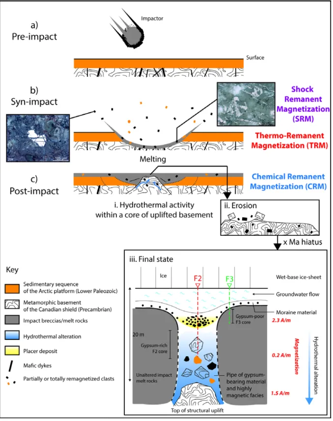
Fig. 10. Simplified model explaining the different pre-, syn- and post-impact geological processes believed to be responsible for the observed geophysical anomalies at the center of the Haughton impact structure. The photomicrographs show a pre-impact anhedral Fe-oxide mineral (left) and syn-impact euhedral skeletal magnetites (right), both within basement clasts. Those minerals may have preserved shock-induced remanent magnetizations (SRM) or thermoremanent magnetizations (TRM). However, most clasts are remagnetized by post-impact hydrothermal processes (c.i) and therefore carry a chemical remanent magnetization (CRM). Erosion (c.ii) and subsequent sedimentary concentration over a hydrothermal pipe (c.iii) are finally responsible for subsurface geophysical (electrical + magnetic) anomalies, while the core of uplifted and altered basement rocks is the main body responsible for the magnetic and gravity anomalies over the impact structure. The indicated total magnetization values are based on measured data (0.2 A/m for F2) and on the model of Quesnel et al 2013.