HAL Id: hal-03156435
https://hal.archives-ouvertes.fr/hal-03156435
Submitted on 2 Mar 2021HAL is a multi-disciplinary open access archive for the deposit and dissemination of
sci-L’archive ouverte pluridisciplinaire HAL, est destinée au dépôt et à la diffusion de documents
Magnetophoresis-Assisted Capillary Assembly: A
Versatile Approach for Fabricating Tailored 3D
Magnetic Supercrystals
Pierre Moritz, Antoine Gonon, Thomas Blon, Nicolas Ratel-Ramond, Fabrice
Mathieu, Pierre Farger, Juan-Manuel Asensio-Revert, Simon Cayez, David
Bourrier, Daisuke Saya, et al.
To cite this version:
Pierre Moritz, Antoine Gonon, Thomas Blon, Nicolas Ratel-Ramond, Fabrice Mathieu, et al.. Magnetophoresis-Assisted Capillary Assembly: A Versatile Approach for Fabricating Tailored 3D Mag-netic Supercrystals. ACS Nano, American Chemical Society, 2021, 15 (3), pp.5096-5108. �10.1021/ac-snano.0c10215�. �hal-03156435�
Magnetophoresis-Assisted Capillary Assembly: A
Versatile Approach for Fabricating Tailored 3D
Magnetic Supercrystals
Pierre Moritz,1,2 Antoine Gonon,1 Thomas Blon,1 Nicolas Ratel-Ramond,3 Fabrice Mathieu,2
Pierre Farger,1 Juan-Manuel Asensio-Revert,1 Simon Cayez,1 David Bourrier,2 Daisuke Saya,2
Liviu Nicu,2 Guillaume Viau,1 Thierry Leïchlé,2,4 Lise-Marie Lacroix.1*
1. Université de Toulouse, Laboratoire de Physique et Chimie des Nano-Objets, UMR 5215 INSA, CNRS, UPS, 135 avenue de Rangueil 31077 Toulouse, France
2. LAAS-CNRS, 7 avenue du Colonel Roche, 31077 Toulouse, France
3. CEMES-CNRS, 29 rue Jeanne Marvig, 31055 Toulouse, France
4. Georgia Tech-CNRS International Research Laboratory, School of Electrical and Computer Engineering, Atlantic Drive, Atlanta, GA, 30332, USA
Corresponding author: lmlacroi@insa-toulouse.fr, Tel: +33567048833, Fax: +33561559697
ABSTRACT. The fabrication and integration of sub-millimeter magnetic materials into predefined circuits is of major importance for the realization of portable devices designed for
telecommunications, automotive, biomedical and space applications, but remains highly challenging. We report here a versatile approach for the fabrication and direct integration of nanostructured magnetic materials of controlled shaped at specific locations onto silicon substrates. The magnetophoresis-assisted capillary assembly of magnetic nanoparticles, either spherical or anisotropic, leads to the fabrication of high-performance Co-based permanent magnets and Fe-based supercrystals. Integrated submillimeter magnets as well as millimetric self-standing magnets exhibiting magnetic properties competing with NdFeB-based composited were obtained through this cost- and time-efficient process. The proof-of-concept of electromagnetic actuation of a MEMS cantilever by means of these supercrystals highlights their potentiality as efficient integrated magnetic materials within nomadic devices.
KEYWORDS. permanent magnet, cobalt nanorods, magnetophoresis, MEMS, nanoparticle-based materials, magnetic nanoparticles, controlled assembly
INTRODUCTION.
The fabrication and integration of sub-millimeter magnetic materials into predefined circuits is of major importance for portable devices used in telecommunications, automotive, biomedical and space applications. For instance, inductors are soft magnetic elements widespread in daily-life objects such as cell phones, where they act as passive filters to properly extract the signal of interest from the electromagnetic noise, or in chargers as passive elements for power electronic converters.1 Furthermore, the expanding market of integrated sensors/actuators requires
miniaturized power supplies. Permanent magnets (PM) represent the most attractive choice for such integrated power sources, and would benefit to numerous applications based on Micro-ElectroMechanical Systems (MEMS), such as actuators,2,3 relays,4 micromachines,5 and sensors
(magnetic, viscosity or biosensors).6,7,8
A major scientific challenge therefore consists in providing submillimeter magnetic materials with optimized properties to address the massive demand for power supplies and converters. Up to now, the fabrication and integration of magnetic materials into portable devices is achieved via three main routes:9
- the sputtering deposition, which gives access to a wide range of materials and a good composition control, but is generally limited to thin films due to low deposition rates and built-in stress that can cause delamination;
- the electrodeposition technique, which can lead to thick films but is restricted to certain materials (Fe, Co, Ni, Pt-based alloys);
- the patterning of magnetic polymers by inkjet, imprinting or photolithography.10
However, in such granular materials, the dilution of the magnetic particles into a polymeric matrix drastically reduces the overall properties.
Nanoparticle-based materials represent a very appealing alternative approach to address both criterions of magnetic performances and submillimetric thickness. This recent class of materials can indeed exhibit enhanced properties with a high level of control compared to bulk material. They benefit not only from the intrinsic properties of the individual nanoparticle building blocks, whose size and shape can be finely tuned thanks to the recent developments in nanochemistry, but also to the collective interactions which could be specifically engineered through the control of the superstructure.11
The formation of nanoparticle super-lattices results from the delicate balance of attractive and repulsive forces and are often assisted by capillary forces. Supercrystals exhibiting enhanced catalytic, electronic or plasmonic properties could be prepared and integrated into optoelectronic devices.12 Surprisingly, magnetic supercrystals have been scarcely addressed and were mostly
limited to superparamagnetic nanoparticles.13
The controlled deposition of nanostructured materials into functional devices still represents a challenge to overcome. Presently, several approaches have been developed: inkjet printing allows a fast patterning of particles, but cannot achieve a thickness over a few micrometers. Serigraphy is suitable to deposit isotropic nanoparticles on a few hundreds of microns, but can hardly be considered to align anisotropic ones without inducing aggregations. Capillary assembly combined with topographic or chemical structuration assists the displacement of the meniscus and moves the particles to pre-defined areas, but was only achieved on micrometer thick films. Due to the fairly long-range of electromagnetic forces, (di)electrophoresis or magnetophoresis technique allows attracting polarizable or magnetic particles over a large volume on predefined substrate14,15 or
In this paper we report a versatile strategy relying on a magnetophoresis-assisted capillary assembly approach for the fabrication of high-performance submillimeter magnetic supercrystals. It consists in the specific attraction and further evaporation of a NP suspension, under an external magnetic field, towards predefined areas exhibiting large magnetic field gradients. The resulting nanostructured materials can be directly integrated into substrates, with well-controlled dimensions and precise positions, or fabricated as self-standing magnets. Their final properties are finely tuned thanks to the different nanoparticle constituents which can be used, such as:
- single-crystalline Co nanorods (NRs), which combine a high magnetization and a large magnetic anisotropy. These anisotropic particles exhibiting hard magnetic behaviour constitute building blocks of primary choice for permanent magnet applications as we previously reported at the macroscopic scale.17,18
- spherical and fairly air-stable iron-based nanoparticles (Fe2.2C NPs), which display soft
magnetic properties (high magnetization and low anisotropy).19
A theoretical overview of the different forces involved in the magnetophoresis process is presented to determine the critical magnetic field gradients to apply, depending on the particle size and shape. Then, the fabrication of individual Co NR magnet and magnet networks is presented using patterned substrate consisting of pairs or arrays of electrodeposited Ni blocks. The magnetically soft Ni blocks effectively serve as flux concentrators inducing local magnetic field gradients which guide Co NR assembly. The optimization of the experimental parameters is further discussed based on finite element simulations and detailed structural and magnetic characterization of the obtained magnets. The efficiency of such nanostructured PM is evidenced by the electromagnetic actuation of a MEMS device. Finally, the magnetophoresis assisted capillary
assembly approach is extended towards i) millimetric self-standing PM using Fe bars as flux concentrators, and ii) integrated soft magnets using Fe2.2C nanoparticles as building blocks.
RESULTS AND DISCUSSION
GENERAL PRINCIPLES OF MAGNETOPHORESIS-DRIVEN CAPILLARY ASSEMBLY.
As depicted in Figure 1, our patterning and assembly method to create localized magnetic supercrystals relies on:
(i) the alignment of nanoparticles dispersed in a highly concentrated suspension thanks to an external magnetic field and their accumulation in zones of strong field gradient (magnetophoresis);
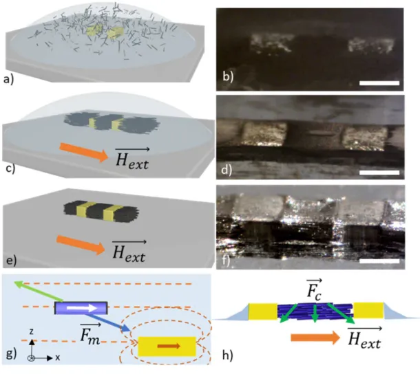
Figure 1. a,c,e) Schematic views of the successive steps of the fabrication process of magnetic
materials and b,d,f) the corresponding optical images, scale bar = 500 µm. a,b) drop casting of concentrated Co NR suspension on a substrate decorated with Ni blocks, c,d) alignment under external magnetic field and attraction towards the magnetized Ni blocks by magnetophoresis, e,f) dense assembly obtained after the complete solvent evaporation. Schematic view of g) the main forces acting on a Co NR in a dilute suspension once placed under a homogeneous external magnetic field and in the vicinity of magnetized Ni block. Dashed orange lines: the magnetic field lines induced by the external field and the Ni blocks. The magnetic moment of the Co NR (white arrow) is fixed along its long axis due to shape anisotropy. ⃗ : magnetophoretic force (in blue)
which drives the particle towards the strong field gradient zones, ⃗ : solvent dragging force (in green), which is opposed to the particle motion and h) ⃗ : the capillary forces encountered during the solvent evaporation.
Combined with microfluidics, magnetophoresis has attracted tremendous interest for the separation and sorting of complex fluids, using a diluted solution of superparamagnetic beads.16,20
Therefore, the analytical description of the phenomenon is well documented for isotropic objects both in presence of high gradients, used in the High Gradient Magnetic Separation (HGMS) technique, and lower ones (Low Gradient Magnetic Separation).21 However, only few reports deal
with anisotropic particles,22,23 thus we will briefly introduce the methodology and determine
qualitatively the critical magnetic gradient allowing for magnetic convection.
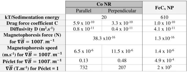
To obtain a proper alignment and a selective assembly by magnetophoresis, the nanoparticle motion must be driven by magnetic convection and not by thermal diffusion. The Peclet number (Pe) allows determining the relative importance of these two contributions and reads as follow:
= . (Eq. 1)
with the typical length of the magnetic nanoparticle (length for a nanorod, diameter for a sphere), the magnetically induced velocity and D the diffusivity of the NP in the solvent. Convective magnetophoresis is predominant when Pe > 1, whereas thermal diffusion is stronger for Pe < 1. Thus, determining the Peclet number will allow ensuring that magnetophoresis conditions are adequate to drive the nanoparticle motion.
In order to determine the magnetic velocity umag, one needs to quantify the different forces called into play and use classical Newtonian dynamics (further details can be found in supplementary).14
nanorods (NRs). Though not realistic, this assumption will allow quantifying the different forces acting on a single Co NR (Length = L = 150 nm, diameter = 2r =15 nm). For comparison, the forces acting on a 15 nm Fe2.2C nanoparticle are given in supplementary.
The weight, which leads to sedimentation, and the opposed buoyancy can be neglected here compared to Brownian motion. The magnetic force ⃗ acts on the particle and moves them to the positive magnetic field gradient (Figure 1g). In our experimental conditions, the external magnetic field is applied along the ⃗ direction. The magnetization ⃗ of the Co NRs is considered uniform along their long axis and independent of ⃗, due to its ferromagnetic character and high anisotropy. The magnetic torque applied on the Co NRs will lead to their alignment along the ⃗ direction. Therefore, the Co NR magnetization reads ⃗ = . ⃗ and thus leads to the simplified form of the magnetophoretic force: ⃗ = ⃗. ∇ ⃗ = . . . ! (Eq. 2)
The drag force ⃗ also applies on the particle due to the surrounding viscous medium. This force is always opposed to the particle motion and depends on the medium viscosity. Considering that the steady-state regime is reached, the drag force compensates the magnetophoretic force ( =
. The magnetophoresis speed is then given by: # =$% with C the drag force coefficient. In the case of anisotropic particle, the drag force has two distinct coefficients, parallel (&∥) and perpendicular (&( to the rod long axis. Thus, the magnetic velocity has itself two components ( ∥⃗ and (⃗ .
Taking into consideration the two diffusivities ()∥ and )() given by hydrodynamic models for an anisotropic particle, two different Peclet numbers ( ∥ and () are finally determined to
describe the motion parallel and perpendicular to the rod long axis:23
∥= ∥∥. = . *+ * . ,-.01/234,67 . 8+9:;01/ (Eq.3) (= <<. = . *+ * . ,-.01/2=4,> .7 8+9:; 01/ (Eq.4)
with the length of the rod and ? its radius, @ the Boltzmann constant, A the temperature (@ . A = 4,11.10-21 J at 300 K) and considering a magnetization m of the Co NR aligned along x, as
schematized in Figure 1g.
NR (dashed lines) moving parallel (black lines) or perpendicularly (red lines) to the long axis. The Peclet number of a single 15 nm Fe2.2C nanosphere is shown in blue.
The critical magnetic field gradients allowing the convective motion of a single Co NR are respectively of approximatively 730 T.m-1 along the long axis of the rod and 210 T.m-1
perpendicularly to it (Figure 2 and Table S1). As stated, this simplified model was applied for a single particle. Considering inter-particle interaction, which favors particle chains formation, leads to a decrease of the critical magnetic field gradients, as previously reported for isotropic nanoparticles.21 As an example, the evolution of the Peclet number is reported for a pair of NRs
aligned along their long axis, the critical values dropped to 180 and 60 T.m-1 respectively (dashed
lines in Figure 2). The convection phenomenon induced by the momentum transfer from the particle to the surrounding fluid,21 which tend to favor the magnetophoresis process,14 is also
neglected here. The critical magnetic field gradients determined through our simplified model should thus be seen as the maximal values mandatory to favor the magnetic convection of a Co NR suspension.
For comparison, the evolution of the Peclet number as a function of the magnetic field gradient is also reported considering non-interacting 15 nm Fe2.2C NPs further used in our study. The
motion of these isotropic NPs could only be driven by diffusion according to our simplified model. We will however see later that the magnetophoresis-driven convection did apply, revealing the importance of inter-particle interactions.19
DIRECTED DEPOSITIONS OF NANOPARTICLES ON PATTERNED SUBSTRATE
Ni blocks of typically 200 µm (length L) x 500 µm (width W) x 150 µm (thickness T) were electroplated on a silicon substrate in order to serve as flux concentrators once placed in a homogeneous external magnetic field (Figure S1a). The Ni blocks exhibit a very weak coercivity (µ0HC= 4 mT, Figures S1b) and a saturation magnetization MS close to the bulk value (MS = 480 ± 2 kA.m-1). The saturation field µ
0Hsat, determined as the field at which the magnetization M = 0.95
MS, was evaluated at µ0Hsat = 285 mT.
Simulations and experimental observation of attractive and repulsive areas
The magnetic field gradients induced by the two Ni blocks were mapped using finite element calculations (Comsol Multiphysics, Figure 3a-c and S2). For an external magnetic field µ0Hext = 1T, classically used in this study, values as high as 3000 T.m-1 were found at the extreme vicinity
of the magnetized Ni blocks. Considering the analytical model previously developed, convection of Co NR will be observed in the regions where the magnetic field gradients overpass the critical values of 730 T.m-1 ( ) and 210 T.m-1 ( , ! . Large attraction zones in the three spatial
directions were evidenced as highlighted on Figure 3. Along the ⃗ direction, the zones were located on both side of each Ni blocks, inducing a potential accumulation of Co nanorods in three main regions: in the gap, which is the targeted area, and at the two extremities. Along the B⃗ and C⃗ directions, attractive gradients were observed in the same three regions, allowing for the Co NR supply through a motion perpendicular to the rod long axis. Repulsion zones were observed laterally to the Ni blocks.
limited. Increasing the field above 50 mT leads to magnetic field gradients overpassing the critical values and thus the appearance of attraction and repulsion zones. The lateral extensions of these zones were characterized by plotting the magnetic field gradient profile on specific lines passing through the center of the Ni blocks (Figure S4). The distances onto which the magnetic field gradients overpass the critical values, and thus would induce the magnetic motion of the NRs, were considered. The lateral extension dx depicted in Figure 3a and 3d corresponds to the attraction zones observed in-between the Ni blocks and was characterized by a magnetic field gradient > 730 T.m-1 (Figure 3a and S4). The lateral extension dy and dz correspond to the repulsion zones
observed on top of the Ni blocks where (or !) > 210 T.m-1 (Figure 3b, c and Figure S4).
Considering the symmetry of our experiments, dy = dz. As shown in Figure 3d, the attraction and repulsion zones spread rapidly with the magnetic field up to 400 mT. Increasing further the external field did not modify the induced magnetic field gradients, the Ni blocks being fully saturated as observed in Figure S1b. The larger extension of the repulsion zone (dy) compared to the attraction zone (dx) is due to the difference in the critical magnetic field gradients required for the magnetic motion of the Co NRs perpendicularly or parallel to the rod long axis, respectively.
Figure 3. Simulated mapping of the magnetic field gradients a) , b) and c) ! induced at the vicinity of two Ni blocks of 200 µm (L) x 500 µm (W) x 150 µm (T) separated by a 500 µm gap and deposited at the Si surface (represented in black in c). The blocks were magnetized by an external field µ0Hext = 1T applied along the ⃗ direction. The observation planes were taken so as
to contain the Ni block centers as shown in Figure S2. Color scales have been adjusted to highlight the critical magnetic field gradients determined in the simplified model. White arrows are guide to the eye for the attractive and repulsive zones as felt by Co NR (which are considered aligned along the ⃗ direction) and the white dashed lines depicted the lateral extension of the attraction (dx) and repulsion (dy, dz) zones. d) Evolution of the spatial extension of the attracted zones (along x, black squares) and repulsion zones (along y, red dots) as a function of the applied magnetic field.
As a proof of concept, a fairly dilute Co NR suspension in anisole ([Co] ~ 20g/L) was drop-casted on top of the Ni blocks. The magnetophoresis-driven motion was followed using an optical camera (Figures 4 and S5, Video S1). Despite the reduced Co concentration, large agglomerates were already observed in absence of any applied field, evidencing the presence of strong interactions between the NRs (Figure 4a). The external magnetic field was progressively increased. At low field, no motion was detected, in agreement with the simulations. At µ0Hext = 40mT, the agglomerates started to move towards the gap and the external attraction zones, as predicted. Increasing the applied magnetic field induced a stronger attraction towards the Ni blocks (Figure 4b). Therefore, a depletion zone, nearly free of particles, progressively formed around the blocks. This zone progressively extended from ~200 µm at 100 mT to ~700µm at 1T (Figure 4c). Similar results were observed at higher concentration (~40 g/L, Figure S6), but the depletion zone only
covered ~400 µm at 1T. The evolution of the extension of the depletion zone as a function of the applied field is reported in Figure 4d. To compare the results obtained on a set of experiments at different concentrations, the extensions of the depletion zones have been normalized with respect to the maximal length measured at 1T. They all follow a similar trend: a fast growth above the critical field of 40 mT to reach a quasi-plateau above 500 mT. The extension of the repulsion zone, determined theoretically was compared. While the simulation predicted a saturation above 400 mT in the case of non-interacting Co NR, the depletion zones kept spreading in our experiments. The difference can be attributed first to the presence of Co NR agglomerates in the suspension, which promote the magnetic convection. The progressive assembly of Co NRs around the Ni blocks can also be invoked. Co NRs exhibit a saturation field of 1.2 T (figure S7), far above the Ni blocks’one (285 mT for 200µm-length Ni blocks). They do contribute to the overall magnetic field gradients, leading to stronger magnetic-convection which kept increasing up to high external field.
Figure 4. Snapshots taken during the deposition of a dilute suspension of Co NRs in anisole
([Co] ~ 20g/L) on top of two Ni blocks of 200 µm (L) x 500 µm (W) x 150 µm (T) and placed in an external magnetic field of a) 0, b) 100 mT and, c) 1 T (video S1). The white arrows are guide to the eye for the Co NR motion. For clarity they are only presented in b) for the left-hand side Ni block. d) Evolution of the normalized extension lengths corresponding to the repulsion zone simulated (red dots) and the depletion zone experimentally observed (black dots). The extension lengths being dependent on the Co NR concentration, the values have been normalized. The dots and the error bars correspond to the mean value and the standard deviation determined from six independent experiments.
Supercrystal fabrication through magnetophoresis-driven controlled deposition
The capillary assembly assisted by magnetophoresis was implemented to fabricate a PM which fulfills the criterions of performance, miniaturization and integration into micro-electronic devices. To fill the entire gap between individual pairs, a concentrated Co NR suspension in anisole ([Co] ~ 80 g/L) was used. The deposition process, consisting of the suspension drop casting, the magnetophoresis-driven assembly, and the washing of nonspecifically deposited Co NRs using an excess of solvent was repeated between two and six times depending on the Ni block thickness. The capillary forces encountered during the complete evaporation of the solvent leads to the partial contraction of the assembly. Additional depositions could be done to fill the resulting free space. For instance, conformal 150 µm thick magnets were classically prepared from six depositions and
three drying steps (Figures 5a-c and S8, Video S2). Similar results were obtained using Co NR suspension in chloroform.
As previously observed for a dilute suspension, Co NR assembly occurred in the attraction zones, corresponding to high magnetic field gradient regions, located on both side of the Ni blocks. Therefore, magnetic material was deposited not only in the gap but also at the extremity of the Ni/Co/Ni structure. The use of an additional resist mask surrounding the Ni blocks allows getting rid of this unwanted deposit after conventional lift-off process (Figure 5d-f). Thus, well-defined Co NR based magnet with controlled geometries and thicknesses were obtained.
The magnetophoresis-based process is well-suited for parallel fabrication. For instance, 144 Co-NR based magnets could be easily simultaneously fabricated using a predefined Ni block array (Figure S9). The 5 mm x 5 mm magnetic array was obtained after only two depositions and a single evaporation step. The Co-NR based magnets exhibit all lateral dimensions closed to the expected ones of 100 µm (L) x 100 µm (W) x 25 µm (T).
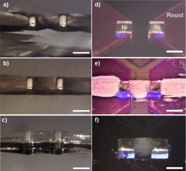
Figure 5: a-c) Snapshots taken during the fabrication process of a Co NR-based PM consisting of
successive deposition and magnetophoresis-driven assembly, washing and solvent drying steps (Video S2). Assembly obtained after a) 1st deposition, b) 3rd deposition and washing, c) final drying
leading to Co NR assembly in the gap and at the two extremities. d-f) Optical images of Ni blocks and the additional resist mask d) as prepared by microfabrication process, e) after the magnetophoresis-driven capillary assembly of Co NRs and f) after the final resist removal by acetone. Scale bar = 500 µm.
Structural characterization of the supercrystal : effect of the external magnetic field
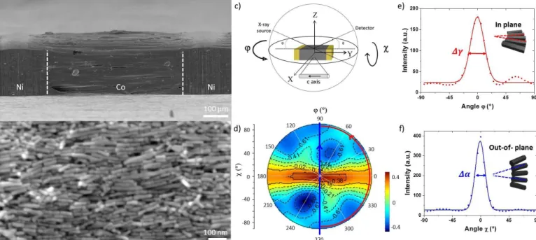
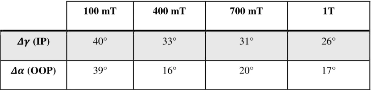
The Co-NR based material prepared under an external magnetic field µ0Hext = 1T was characterized by SEM (Figure 6a-b). At the surface, nanorods were fairly well aligned along the external magnetic field direction, an angular dispersion of 16° being determined. The orientation distribution of the alignment was quantified on the whole material using XRD measurements in the so-called texture mode (Figure 6c). The pole figure obtained for the (101F0) reflection is strongly anisotropic with a maximum intensity at ϕ = 0° and 180° and for all χ values between 0 and 90° (Figure 6d). This figure shows that the c axis of the rods, which is also their long axis, is mostly parallel to the y axis, with a random orientation of the a and b axis in the (x, z) plane. In this pole figure, the in-plane and out-of-plane orientation distributions of the NRs c axes are given by the intensity profile I(ϕ) plotted as a function of ϕ for χ = 90° (i.e. along the red dashed line in Figure 6d), and by the intensity profile I(χ) plotted as a function of χ for ϕ=90 and 270° (i.e. along the white dashed line), respectively (see details in Supplementary materials). Gaussian functions were fitted to the intensity profiles I(ϕ) and I(χ) (Figure 6e-f). The full width at half maximum of the two Gaussian functions, Δγ and Δα, describe the quality orientation distributions, in plane and out of plane, respectively. The values Δγ = 26° and Δα = 16° were found for the alignment under µ0Hext = 1T.
The effect of the external magnetic field value on the alignment quality was studied following the same method (Figure S10). The full width at half maximum, Δγ and Δα of the intensity profiles
I(ϕ) and I(χ) of the pole figures are summarized in Table 1. For an applied field of 100 mT, the pole figure obtained was fairly isotropic, revealing a poor alignment of the Co NRs. The in-plane Δγ and out-of-plane Δα were both evaluated at ca. 40°. At 400 mT, the characteristic anisotropic figure was observed. The alignment quality improved at higher fields, as revealed by Δγ which
dropped down to 26° at 1T (Table 1). Δα remains fairly constant above 400 mT, thus a good compromise between alignment quality and external magnetic field constraint could be reached for a critical magnetic field of ~400 mT. This value further confirms the previous results obtained by simulations and preliminary experiments at low concentrations.
Figure 6: a-b) SEM images of Co NR-based supercrystal deposited between two individual Ni
blocks of 200 µm (L) x 500 µm (W) x 150 µm (T). b) Magnified view of the constituting Co NRs. c) Schematic view of the X-Ray texture mode consisting in analyzing the spatial distribution of a given crystallographic plane. d) The reconstructed (101F0) pole figure and the corresponding intensity profiles e) I(φ) measured at χ = 80° and f) I(χ) measured at φ = 90 and 270°. The full width at half maximum of the peaks allows quantifying the orientation distribution of the Co NR assembly in plane (Δγ = FWHM(I(φ))) and out-of-plane (Δα = FWHM(I(χ))).
Table 1: Evolution of the FWHM of the in plane (IP) and out of plane (OOP) orientation
distribution determined on the pole figures as a function of the external magnetic field applied during the magnetophoresis.
100 mT 400 mT 700 mT 1T
GH (IP) 40° 33° 31° 26°
GI (OOP) 39° 16° 20° 17°
Magnetic characterization of the Co NR-based material
The alignment and compacity of the supercrystal prepared in the optimal conditions of µ0Hext = 1T were studied by Vibrating Sample Magnetometry. After Ni blocks removal, the room temperature magnetization was measured as a function of the applied field (Figure 7a). A broad hysteresis cycle, characterized by a large coercive field µ0HC = 590 mT was obtained.
The degree of magnetic alignment was characterized by the MR/MS ratio, as classically established.24 Experimentally, M
R/MS = 0.85 evidencing a fairly good alignment of the rod long axes, in agreement with XRD results.
The magnetic volume fraction of the supercrystal could be determined from the absolute saturation magnetization measured and the total volume estimated from SEM and profilometric measurements (see Experimental section for details). The obtained magnetization was then compared to the bulk value (Ms Co = 1440 kA.m-125) to evaluate the magnetic volume fraction.
A magnetic volume fraction fv = 29 ± 2% was determined. Such a value is typically obtained for
materials prepared with Co NRs. The Co NRs are indeed complex objects composed of a metallic cobalt core surrounded by a 1.2 nm-thick cobalt oxide shell and 3.5nm-thick surface ligands, the
core being the only part contributing to the magnetic volume fraction. Considering perfectly aligned hexagonal arrays of Co NRs with similar features (2r = 15 nm, L = 150 nm) leads to a maximum magnetic volume fraction of fv MAX =37 %, not that far above the experimental values obtained here.17
Considering the experimental magnetic volume fraction, one could extrapolate the induction curve B(H) and the energy product, (BH)max. = 30 ± 3 kJ.m-3 (Figure 7b). Such energy product
competes with the best values reported for comparable sub-millimeter sized magnets prepared with NdFeB-based magnetic polymers.26
Figure 7: a) Magnetic measurement recorded at 300K of the c.a. 500 µm x 500 µm x 150 µm
Co-NR based magnets. b) 2nd quadrant of the magnetic induction as a function of the applied
field H and of the energy product (BH). The maximal area corresponding to the (BH)max on the
B(H) curve is highlighted with dashed line as a guide for the eye. Value of 30 kJ.m-3 was found
considering fv = 29 %. c) Evolution of the in-plane magnetic stray field intensity experimentally measured by Hall micro-probe as a function of D, the distance from the magnet. Solid lines: the simulated induction considering fv = 31%. Inset: schematic view of the set-up, the black arrow highlighted the distance D between the probe and the magnet.
The magnetic induction generated by the Co NR supercrystal was measured via a Hall-effect micro-probe (figure 7c). The induction profile was determined as a function of the distance to the magnet D. At the minimal distance of 70 µm, a magnetic induction as high as 100 mT was reached. Induction of 36 mT and 20 mT were still measured at D = 200 µm and 300 µm respectively.
The experimental induction profile has been fitted using finite element simulations, considering the supercrystal geometry, as determined by SEM, the experimental M(H) curve and the magnetic volume fraction as free parameter. The best adjustment was obtained for fv = 31 % in agreement with the magnetometry results.
The long-range extend of the induced stray field can be compared to the previous reported results. For instance, the induction generated by NdFeB powder-based micromagnets (25 µm x 25 µm x 10 µm) vanishes at D = 50 µm.27 The outstanding NdFeB sputtered magnets (50 µm x 2000
Proof-of-concept : actuation of a gravimetric MEMS device using Lorentz force
To demonstrate the potentiality of Co-NR supercrystals as integrated permanent magnet, the actuation of a microelectromechanical system (MEMS) gravimetric sensor,7 consisting of a
freestanding vibrating Si microcantilever, was studied (Figure 8a). Such device can be used for
e.g. rheological measurements or to detect molecule absorption where addition of a mass at the
surface of the cantilever induces a shift in the MEMS resonance frequency. The actuation of this MEMS sensor relies on electromagnetic transduction that uses the Lorentz force and requires both an AC current i(t) circulating in metal lines patterned on the microcantilever and an external magnetic induction. The vibration of the cantilever is detected here by means of integrated piezoresistors.
The optimized Co NR-based magnet was placed in front of the cantilever at a distance d varying between 70 µm and 600 µm (Figure 8b). An actuation current of 30 mA supplied the device while the piezoresistors were polarized at 1 V. The figure 8c shows the first resonance peak at a frequency of 31.1 kHz, detected by means of the output piezoresistor voltage (Vout). The amplitude of the resonance peak decreases with the distance between the cantilever and the Co NR-based magnet as evidenced for D = 100, 200 and 300 µm. The evolution of the resonance peak amplitude as a function of D was reported on Figure 8d. The decay observed perfectly matches the magnetic induction profile of the Co NR supercrystal, confirming that the nanostructured magnet is responsible for the MEMS actuation up to distances of 600 µm. The submillimeter Co NR-based magnet successfully replaced the centimetric NdFeB magnets typically used for the device actuation (Figure S11).
Figure 8: a) Schematic view of a MEMS gravimetric sensor consisting of a Si microcantilever
actuated by Lorentz force thanks to the applied AC current i(t) and the permanent induction ⃗. The vibration is detected by means of integrated piezoresistors. b) Optical image of the Co NR-based magnet placed in front of the microcantilever. White arrows: the adjustable distance D between the magnet and the cantilever. c) Piezoresistors output signal Vout as a function of the AC current frequency for a distance to the magnet D of 100 µm (black), 200 µm (red) or 300 µm (blue) and d) the corresponding maximum value (Vout max) at the cantilever’s resonance as a function of
D, the distance to the magnet. In red: the experimental (open circles) and simulated (solid line)
VERSATILITY OF THE MAGNETOPHORESIS ASSISTED FABRICATION PROCESS
The fabrication process based on magnetophoresis assisted assembly was extended to i) self-standing permanent magnets with larger dimensions and to ii) soft magnets based on dense arrays of spherical nanoparticles.
Fabrication of a millimeter sized permanent magnet
Magnetophoresis-assisted capillary assembly of Co NRs was studied for the fabrication of millimeter sized self-standing magnets. The electrodeposited Ni blocks which so far were used as flux concentrators were replaced by two commercial Fe bars embedded in a Teflon mold and facing each other (inset Figure 9a). The diameter of the Fe bars and the distance between them could be adjusted to tune the final dimension of the nanostructured magnet. We focus here on 2 mm diameter Fe bars separated by a 2 mm gap and magnetized by an external magnetic field of µ0Hext = 1 T. The magnetic field gradients induced by the bars were simulated using Comsol Multiphysics (Figure S12). Local magnetic field gradients up to 3000 T.m-1 were predicted, far
above the critical values of 730 T.m-1 and 210 T.m-1 required to attract the Co NRs according to
our simplified model.
The mold cavity was filled with 600 µL of a Co NR suspension in anisole ([Co] ~ 16 g/L) prepared from the same Co NRs (2r = 15 nm, L = 150 nm) as the one used for the submillimeter magnet previously described. The magnetophoresis was performed under the optimized external magnetic field of µ0Hext = 1T. Within only few seconds, all the Co NRs present in the suspension were attracted in the gap. The colorless solvent was discarded and the Co NRs material washed
with an excess of solvent. A second addition of Co NR was performed to fill the entire gap volume. After proper washing and complete evaporation of the solvent, a compact self-standing supercrystal with a length and a diameter of 2 mm was obtained, these dimensions being conformal to the geometry of the gap (Figure 9a-b). Though prepared solely from Co NRs, the material exhibits mechanical robustness allowing an easy separation from the two Fe bars. The millimeter magnet has a very shiny aspect, revealing fairly smooth surfaces and thus proper alignment of the rods.
The magnet density could be determined thanks to the direct measurement of its weight (m = 24.7 ± 0.1 mg) and its volume (V = 6.3 ± 0.6 mm3). A value of ρ
magnet = 3.9 ± 0.4 g.cm-3 was determined corresponding to 44 ± 4 % of the density of bulk Co (ρCo = 8.9 g.cm-3). The magnetic volume fraction, which is only sensitive to the Co core, was determined at fv = 36 ± 3 % (see experimental section for details). The density and the magnetic volume fraction values are in agreement with perfectly aligned 15 nm diameter Co NRs exhibiting a 1.2 nm thick oxide shell, and separated by a 3.5 nm distance resulting from the organic surfactant corona.17
The magnet exhibits a broad magnetization cycle at room temperature which is comparable with the submillimeter integrated magnet’s one (Figure 9c and Table 2). The magnetic alignment and coercivity are fairly similar (MR/MS = 0.81 and 0.85, respectively; µ0HC = 590 mT in both cases). The difference in magnetization between the two type of magnets arises from the magnetic volume fraction, which is slightly higher in the millimeter-scale magnet (fv = 36 % and 29 %, respectively). Thanks to this improvement, the maximal energy product reaches (BH)max = 37 ± 3 kJ.m-3 for the millimetric magnet.
Figure 9: a-b) Optical images of the self-standing 2 mm thick magnet prepared solely from 15 nm
two Fe bars embedded in a Teflon mold (inset). c) 300 K magnetization cycle and d) 2nd quadrant
of the magnetic induction as a function of the applied field (B(H)) and of the energy product (BH), considering fv = 36 %. Dashed line: working point corresponding to the (BH)max. e) Resonance amplitude of gravimetric MEMS sensor detected by means of piezoresistors for different magnet to microcantilever distances (D). Inset: Optical image of the millimetric magnet placed in front of the cantilever. f) Evolution of the corresponding maximum value (Vout max) at the cantilever’s
resonance (black squares) and the magnetic induction measured by Hall microprobe (red open circle) and simulated considering fv = 36 % (red solid line).
Due to the good magnetic properties and the large volume of this millimetric magnet, intense stray fields were induced on a large-range distance. The induction profile was mapped from few hundred of microns to few millimeters using Hall-microprobe (Figure 9f). Induction field larger than 20 mT were measured up to a 2 mm distance. This long-range extension was further confirmed by the actuation of MEMS gravimetric sensor. As evidenced in Figure 9e, the resonance of the vibrating microcantilever is clearly observed up to magnet-to-cantilever distance of 2 mm.
Table 2: Comparison of the magnetic properties of the Co-NR based material fabricated as
submillimeter magnet or self-standing millimeter magnet.
Dimensions µ0Hc (mT) MR/MS fv - VSM (%) (BH)max (kJ.m-3) B (mT) fv – Hall (%) Integrated magnet 500 µm x 500 µm x 150 µm 590 0.85 30 ± 2 30 ± 3 B100µm 80 mT 31 Self-standing 2r = 2mm B
Preparation of soft magnetic materials
We investigated the potentiality of the magnetophoresis-driven capillary assembly to fabricate soft magnetic materials. For that, monodisperse iron carbide nanospheres (Fe2.2CNPs) with a mean
diameter of 15 nm and a size dispersion σ = 7% were used (Figure S13). As previously described in section I, the simple theoretical model we developed considering non-interacting NP predicted a motion only driven by diffusion in our experimental conditions. Indeed, the magnetic field gradients generated by the magnetized 200 µm-length Ni blocks reach at most 3000 T.m-1 (Figure
3), far below the 2.105 T.m-1 field gradient required to establish the convection-regime (see
supplementary information).
Experimentally, the Fe2.2C NPs contained in the colloidal solution ([Fe2.2C] ~ 15g/L in
mesitylene) were however rapidly and selectively attracted towards the Ni blocks once magnetized under an external magnetic field µ0Hext = 1T. Thus, the presence of magnetic interaction within the fairly concentrated colloidal solution promoted the magnetophoresis convection over the Brownian motion.
Magnetic arrays and individual soft magnets, with conformal geometries compared to the Ni blocks could be prepared as shown in Figure 10a-b. SEM images of the supercrystal surface evidence nearly defect-free hexagonal closed packed structures on micrometric areas (Figure 10c).
Figure 10. SEM images of Fe2.2C-based supercrystal integrated as a) a magnetic array of 100 µm
(L) x 100 µm (W) x 25 µm (T) and b) individual soft magnet of 500 µm (L) x 500 µm (W) x 145 ± 5 µm (T). c) Magnified view of the constituting Fe2.2C NPs revealing hexagonal dense packing
with only few defects. Inset: Fast Fourier Transform (FFT) of the image evidencing the 6-fold symmetry of the arrangement.
The Fe2.2C-based supercrystal exhibits soft magnetic properties at room temperature, with a
coercive field µ0HC = 25 mT. Considering the volume of the supercrystal determined by SEM, a saturation magnetization MS = 400 ± 20 kA.m-1 and a magnetic volume fraction of fV = 33 ± 2% could be estimated (Figure S17).
CONCLUSION.
We report here a fairly simple and fast fabrication process for integrated magnetic materials based on the controlled assembly of individual nanoparticles. NRs and nanospheres are efficiently arranged into supercrystals through a magnetophoresis-driven capillary assembly process leading to performant rare-earth free magnets and soft magnetic supercrystals. The fabrication process, based on pre-patterned ferromagnetic flux concentrator structures is suited to the fabrication of integrated submillimetric magnets with tuneable geometries as well as millimetric self-standing structures. The overall fabrication process is highly cost efficient, since the magnetophoresis forces attracts most of the nanoparticles diluted in the drop-cast solution to assemble them in the final supercrystal. This process is also time efficient, since only a few minutes is needed to obtain NP-based materials with the designed outer shape and density. The efficiency of the rare-earth NP-based permanent magnet prepared from Co NRs was evidenced through the electromagnetic actuation of a MEMS cantilever. Soft magnets were efficiently prepared from Fe-based nanoparticles. In all the examples described, the particles were handled in air. The magnetophoresis-driven assembly process can however be performed under inert atmosphere to avoid the NP surface oxidation and to increase the magnetic volume fraction of the assemblies. Being not limited by the NP size, shape or chemical composition, this fabrication process can be as well extended to other magnetic NPs.
EXPERIMENTAL SECTION.
Fabrication of the decorated substrate
1. Electroplating of Ni blocks
25 to 150 µm thick nickel blocks were electroplated onto a silicon substrate using conventional microfabrication procedure. The fabrication process is further detailed for 150 µm thick Ni blocks. First, a conductive seed layer constituted of 100 nm Ti / 200 nm Cu was evaporated onto a 4-inches Si wafer with a thickness of 525 µm. Then, a 200 µm thick dry film was elaborated by the lamination at 100°C of two 100 µm negative films of WBR 2100 (Dupont) on the substrate. The resist was then exposed by photolithography at a power of 1.5 J/cm² and a wavelength of 365 nm. The resist was developed via its immersion in Na2CO3 developer at room temperature during 20
min. This 200 µm thick film acts as a mold for the electrochemistry, the film is thicker than the targeted Ni in order to improve the deposition homogeneity on the wafer. Then, nickel was electroplated inside Yamamoto-MS cell plating with a NB Semi Plate Ni 100 bath (NB Technology) applying 3 A.dm-2 equivalent to a plating speed of 0.7 µm/min. The resist was finally
stripped by NF52 at 70 °C during 25 min and the Cu/Ti seed layer was etched using a mixture of sulfuric acid and hydrogen peroxide at 1% of each, and a 5 % hydrofluoric acid solution to remove the Ti layer.
2. Imprint of a resist mask
films of WBR 2100 were laminated together to form a film of 200 µm. This thick film was then imprinted under vacuum to avoid the accumulation of air bubbles between the substrate and the resist by the NX-2500 Nanoimprintor at 85 °C at 30 Psi during 120 s. The resist was then exposed by photolithography at a power of 1.5 J/cm² and a wavelength of 365 nm. The resist was developed by immersing it in Na2CO3 developer at room temperature during 20 min. Finally, the substrate
was diced with a diamond saw on a chip presenting 1x1 cm2lateral dimensions.
Magnetophoresis experiment
1. Nanoparticle synthesis
Co nanorods (NRs): Cobalt (II) acetate hydrate (Alfa Aesar), NaOH (Acros), RuCl3.xH2O
(SigmaAldrich, 99.98%), 1,2-butanediol (Sigma-Aldrich), Na-(C11H23COO) (Aldrich, ≥99%) were purchased and used without any further purification. Cobalt nanorods were synthesized by the polyol process following a protocol previously described.17 First, cobalt (II) laurate was
prepared by mixing equimolar cobalt acetate and sodium laurate to obtain a pink precipitate. This one was washed with deionized water and dried at 50 °C during one week. Then, Co(C12H23O2)2
was mixed in 120 mL of a basic solution of 1,2 butanediol at 0.08 mol.L-1 ([Co] = 4.7 g/L).
Ruthenium chloride salt is added ([Ru]/[Co]=2.5%) and the mixture heated at 175°C. After 20 min, the reduction of Co(II) complexes to metal was complete. Then, the black suspension was cooled down at room temperature and the Co NRs were separated from the butanediol by magnetic attraction. Particles were washed with absolute ethanol till the supernatant was colourless. Additional washing with chloroform allows removing the unreacted species and the ligand excess.
Fe2.2C nanoparticles (NPs) were synthesized using a carbidization process previously reported.19 Fe0 NPs were dispersed in mesitylene before being pressurized at 150 °C for 24 h with CO/H2 (3
bar of a 1:1 mixture of both gases) for 4 days. Then, the NPs were decanted with the help of a magnet, washed with 3x10 mL of toluene and dried under vacuum to form a black powder. They were re-dispersed in degassed mesitylene just before the deposition step.
2. Preparation of the concentrated NP suspension
Highly concentrated NP suspension were prepared by dispersing the magnetic nanoparticle of interest (Co NRs or Fe2.2C) into the solvent of choice (anisole, chloroform or mesitylene). Stored
in the reaction medium, Co NRs were magnetically extracted and purified using chloroform. Typically, 20 mL of chloroform is added to 10 mL of the mother liquor solution. After 5 min of sonication, the particles are magnetically attracted. The procedure is repeated 4 times, until the supernatant was colourless. Based on Gas chromatography-mass spectrometry (GC-MS) of the discarded supernatant, thermogravimetric analysis (TGA) and magnetometry measurements (VSM) of the obtained Co NR, we could determine that four washing/precipitation with chloroform allowed removing the solvent (butanediol and the product of its oxidation(1-hydroxy-2-butanone)) and the surfactant in excess (laurate). After such treatment, the mass fraction of the laurate surfactant was of 8%, matching with the theoretical value expected for a monolayer of surfactant at the rod surface. It allows stabilizing the suspension of Co NR during the few minutes of the magnetophoresis-assisted assembly without altering too much the magnetic volume fraction in the final supercrystal. The obtained NRs were redispersed into 600 µL of anisole leading to a Co suspension with an estimated concentration of approximatively 80 g/L. In the case of the 25 µm thick magnetic array, a suspension diluted twice is used. ([Co] ~ -40g/L following the same
The Fe2.2C NPs were stabilized by a mixture of acid (palmitic acid) and amine (hexadecylamine).
After three magnetic-assisted washing with toluene, TGA and VSM revealed a mass fraction of surfactants of 20%. Once redispersed in mesitylene, the NPs were fairly stable in suspension, even at high concentration.
3. Magnetophoresis-driven capillary assembly
The 1 x 1 cm² samples consisting of Si chip patterned with Ni blocks were placed in the center of a 2 cm length cavity of a Teflon mold. The mold was set in an electromagnet generating a uniform magnetic field varying between 0 and 1 T (see supplementary figure S1). The local deposition of the magnetic nanoparticles was performed following a three-step impregnation process. i) In absence of any magnetic field, 10 µL of the dense colloidal suspension was deposited on the substrate using a micropipette. ii) A 1 T magnetic field was then applied, leading to the alignment of the magnetic nanoparticles and their attraction by the Ni blocks. iii) After 30 s, the suspension was washed away with 500 µL of chloroform. The impregnation was classically repeated three times, before allowing the solvent evaporating at room temperature and atmospheric pressure. Depending on the suspension concentration and the targeted magnetic layer thickness, the deposition process (3 impregnations and 1 evaporation) can be repeated several times. In the case of the deposition through a resin mask, a lift-off process was finally realized, the sample was immersed 5 min in an acetone bath and then rinse with ethanol and DI-water.
The generated magnetic field gradients were simulated using Comsol Multiphysics 4.3. First, the magnetic induction was calculated by solving the first Maxwell equation in stationary regime using the Magnetic Field No Current (MFNC) module. A 50 µm mesh size was used as a good compromise between resolution and extended computational time. The uniform external field generated by the electromagnet was implemented through magnetic potentials of 1600 W/m and 0 W/m, respectively on the opposite faces of a 4 mm3 air box. Two Ni blocks were placed in the
middle of the box and were defined via magnetic flux conservation. Their magnetization was specified using experimental hysteresis cycles. Then, the 3D magnetic induction gradients were calculated using the Coefficient Form PDE module considering three dependent variables u1, u2,
u3 which correspond to each spatial component of the magnetic induction. These Lagrangian
elements were derived spatially at the first order to obtain the magnetic field gradient in the air box.
Structural and magnetic characterizations
Scanning electron microscopy (SEM) were performed using a JEOL JSM 6700F microscope at an accelerating voltage of 15 kV and a current of 8 µA. Powder X-ray diffraction measurements were performed on a PANalytical Empyrean diffractometer using Co-Kα radiation and equipped with a linear Pixcel1D detector. Texture characterization of rods assembly were performed with a Brucker D8 Discover diffractometer equipped with a Co micro-source, a 2D Vantec-500 detector and a 300 µm collimator. The Bragg-Brentano angle 2θ was set to 48.9° to probe the (10-10) orientation plane of the rod assembly. The sample holder was rotated in plane of an angle φ varying between 0° and 359° through successive 20° steps while three rotations out of plane were
performed at χ values of -13.9°, -47,4° and -80.9°. The 2D images were processed by the software Maud and fitted using a harmonic spherical model to yield the pole figure.
The magnetic properties of the rod assemblies were characterized using a Quantum Design Physical Property Measurement System (PPMS) with the Vibrating Sample Magnetometer (VSM) configuration. The hysteresis measurements in the parallel configuration (applied field along the material anisotropy axis) were done at room temperature between -3 and +3 T.
The magnetic volume fraction JK within the supercrystal was calculated from the saturation magnetization MS recorded at 3 T (expressed in emu), the supercrystal volume estimated by SEM
(expressed in cm3) and the expected bulk magnetization (for Co : L
M,%N O :8 = 1440 kA.m-1,26 for
Fe2.2C : LM,$P% O :8 = 1200 kA.m-1 19) as follow :
JK = QR,S T 8U.
VW
QR,XYZ[ 8U. VW (Eq.5)
Where LM,P \ @]. 3^ = LM,P \ . _ 3` =QR P
a b (Eq. 6)
The energy product (BH)max was determined from the B(H) loop, which was extrapolated from the M(H) loop considering: = µ4 d + L (Eq. 7)
Magnetic characterizations were realized via a Hall-effect micro-probe.29 This sensor was
instrumented via an acquisition card Ni 6341 from National Instruments which polarized an electronic circuit, providing a constant current of 50 µA to the probe and measuring the Hall voltage in real-time. The Hall constant of the micro-probe was preliminary calibrated using a coil and the gaussmeter BGM 101 (Brockhaus Measurements). A Hall constant k = 200 Ω.T-1 was
determined. The Hall-effect micro-probe was mounted on a (XY) plane, while the supercrystal was placed on a moving stage (A2V Mécatronique) to control the z position.
MEMS actuation
MEMS devices, fabricated for rheological applications, consisted of two 840 µm long, 100 µm wide and 20 µm thick cantilevers: a reference cantilever fixed to the handling substrate and a freestanding cantilever able to vibrate using electromagnetic force actuation. Lorentz force was generated upon injection of a sinusoidal current f to the conducting path patterned onto the cantilevers (scheme in supplementary) and perpendicular to a static magnetic field generated by a neighboring permanent magnet. The vibration amplitude reaches a maximum when the frequency of the actuation current equals the mechanical resonance frequency of the microsystem. To detect this resonance peak, piezoresistors were integrated at the clamped-end of the cantilevers, where the stress induced by the deformation is maximal. Mechanical oscillations were converted by the piezoresistors to a variation of resistance ∆R/R and measured by a vector network analyzer which generates two complementary voltages and measures the output signal of a transimpedance amplifier.
Supporting Information Available
Details of the different forces called into play during the magnetophoresis-assisted capillary assembly considering isotropic (Fe2.2C NPs) or anisotropic objects (Co NRs). Video recorded
during the assembly of Co NRs from a dilute suspension (20g/L) (Video S1) and during the complete fabrication process of a permanent magnet (Video S2) and additional snapshots. TEM images and magnetic hysteresis of the starting nanoparticles (Fe2.2C NPs and Co NRs). Additional
simulations of the magnetic field gradients induced by Ni blocks or Fe bars, and the corresponding 2D maps and profile evolution. Additional SEM and XRD characterization of the final supercrystal
ACKNOWLEDGMENT
PM thanks the Région Occitanie and the Université Fédérale de Toulouse for phD funding. This study has been partially supported through the French national project POMADE (ANR 19-CE09-0021-01), the EUR grant NanoX n° ANR-17-EURE-0009 in the framework of the « Programme des Investissements d’Avenir, the prematuration program of the Région Occitanie (AimCap) and the SATT TTT (Soft Magneto). This work has been supported by the technology platform of LAAS-CNRS, Member of the French RENATECH network. JMA thanks the ERC Advanced Grant (MONACAT 2015-694159) for financial support. Marc Respaud and Sébastien Pinaud are warmly thanked for fruitful discussion and technical support.
REFERENCES
(1) Rodriguez-Sotelo, D.; Rodriguez-Licea, M. A.; Soriano-Sanchez, A. G.; Espinosa-Calderon, A.; Perez-Pinal, F. J. Advanced Ferromagnetic Materials in Power Electronic
Converters: A State of the Art. IEEE Access 2020, 8, 56238–56252.
https://doi.org/10.1109/ACCESS.2020.2982161.
(2) Yunas, J.; Mulyanti, B.; Hamidah, I.; Mohd Said, M.; Pawinanto, R. E.; Wan Ali, W. A. F.; Subandi, A.; Hamzah, A. A.; Latif, R.; Yeop Majlis, B. Polymer-Based MEMS Electromagnetic Actuator for Biomedical Application: A Review. Polymers 2020, 12 (5), 1184. https://doi.org/10.3390/polym12051184.
(3) Mohd Ghazali, F. A.; Hasan, M. N.; Rehman, T.; Nafea, M.; Mohamed Ali, M. S.; Takahata, K. MEMS Actuators for Biomedical Applications: A Review. J. Micromechanics
Microengineering 2020, 30 (7), 073001. https://doi.org/10.1088/1361-6439/ab8832.
(4) Schiavone, G.; Desmulliez, M.; Walton, A. Integrated Magnetic MEMS Relays: Status of the Technology. Micromachines 2014, 5 (3), 622–653. https://doi.org/10.3390/mi5030622. (5) Song, Y.; Panas, R. M.; Hopkins, J. B. A Review of Micromirror Arrays. Precis. Eng. 2018,
51, 729–761. https://doi.org/10.1016/j.precisioneng.2017.08.012.
(6) Niekiel, F.; Su, J.; Bodduluri, M. T.; Lisec, T.; Blohm, L.; Pieper, I.; Wagner, B.; Lofink, F. Highly Sensitive MEMS Magnetic Field Sensors with Integrated Powder-Based
(7) Boudjiet, M. T.; Bertrand, J.; Mathieu, F.; Nicu, L.; Mazenq, L.; Leïchlé, T.; Heinrich, S. M.; Pellet, C.; Dufour, I. Geometry Optimization of Uncoated Silicon Microcantilever-Based Gas Density Sensors. Sens. Actuators B Chem. 2015, 208, 600–607. https://doi.org/10.1016/j.snb.2014.11.067.
(8) Javor, J.; Stange, A.; Pollock, C.; Fuhr, N.; Bishop, D. J. 100 PT/Cm Single-Point MEMS Magnetic Gradiometer from a Commercial Accelerometer. Microsyst. Nanoeng. 2020, 6 (1), 71. https://doi.org/10.1038/s41378-020-0173-z.
(9) Arnold, D. P.; Naigang Wang. Permanent Magnets for MEMS. J. Microelectromechanical
Syst. 2009, 18 (6), 1255–1266. https://doi.org/10.1109/JMEMS.2009.2034389.
(10) Pallapa, M.; Yeow, J. T. W. A Review of the Hybrid Techniques for the Fabrication of Hard Magnetic Microactuators Based on Bonded Magnetic Powders. Smart Mater. Struct. 2015,
24 (2), 025007. https://doi.org/10.1088/0964-1726/24/2/025007.
(11) Chen, J.; Ye, X.; Murray, C. B. Systematic Electron Crystallographic Studies of Self-Assembled Binary Nanocrystal Superlattices. ACS Nano 2010, 4 (4), 2374–2381. https://doi.org/10.1021/nn1003259.
(12) Talapin, D. V.; Lee, J.-S.; Kovalenko, M. V.; Shevchenko, E. V. Prospects of Colloidal Nanocrystals for Electronic and Optoelectronic Applications. Chem. Rev. 2010, 110 (1), 389–458. https://doi.org/10.1021/cr900137k.
(13) Marino, E.; Keller, A. W.; An, D.; van Dongen, S.; Kodger, T. E.; MacArthur, K. E.; Heggen, M.; Kagan, C. R.; Murray, C. B.; Schall, P. Favoring the Growth of High-Quality, Three-Dimensional Supercrystals of Nanocrystals. J. Phys. Chem. C 2020, 124 (20), 11256– 11264. https://doi.org/10.1021/acs.jpcc.0c02805.
(14) Fratzl, M.; Delshadi, S.; Devillers, T.; Bruckert, F.; Cugat, O.; Dempsey, N. M.; Blaire, G. Magnetophoretic Induced Convective Capture of Highly Diffusive Superparamagnetic
Nanoparticles. Soft Matter 2018, 14 (14), 2671–2681.
https://doi.org/10.1039/C7SM02324C.
(15) Tanase, M.; Silevitch, D. M.; Hultgren, A.; Bauer, L. A.; Searson, P. C.; Meyer, G. J.; Reich, D. H. Magnetic Trapping and Self-Assembly of Multicomponent Nanowires. J. Appl. Phys.
2002, 91 (10), 8549. https://doi.org/10.1063/1.1452206.
(16) Alnaimat, F.; Dagher, S.; Mathew, B.; Hilal‐Alnqbi, A.; Khashan, S. Microfluidics Based
Magnetophoresis: A Review. Chem. Rec. 2018, 18 (11), 1596–1612.
https://doi.org/10.1002/tcr.201800018.
(17) Anagnostopoulou, E.; Grindi, B.; Lacroix, L.-M.; Ott, F.; Panagiotopoulos, I.; Viau, G. Dense Arrays of Cobalt Nanorods as Rare-Earth Free Permanent Magnets. Nanoscale 2016,
8 (7), 4020–4029. https://doi.org/10.1039/C5NR07143G.
(18) Ener, S.; Anagnostopoulou, E.; Dirba, I.; Lacroix, L.-M.; Ott, F.; Blon, T.; Piquemal, J.-Y.; Skokov, K. P.; Gutfleisch, O.; Viau, G. Consolidation of Cobalt Nanorods: A New Route for Rare-Earth Free Nanostructured Permanent Magnets. Acta Mater. 2018, 145, 290–297. https://doi.org/10.1016/j.actamat.2017.12.009.
(19) Asensio, J. M.; Marbaix, J.; Mille, N.; Lacroix, L.-M.; Soulantica, K.; Fazzini, P.-F.; Carrey, J.; Chaudret, B. To Heat or Not to Heat: A Study of the Performances of Iron Carbide Nanoparticles in Magnetic Heating. Nanoscale 2019, 11 (12), 5402–5411. https://doi.org/10.1039/C8NR10235J.
(20) Alnaimat, F.; Karam, S.; Mathew, B.; Mathew, B. Magnetophoresis and Microfluidics: A
(21) Leong, S. S.; Ahmad, Z.; Low, S. C.; Camacho, J.; Faraudo, J.; Lim, J. Unified View of Magnetic Nanoparticle Separation under Magnetophoresis. Langmuir 2020, 36 (28), 8033– 8055. https://doi.org/10.1021/acs.langmuir.0c00839.
(22) Lim, J.; Yeap, S. P.; Leow, C. H.; Toh, P. Y.; Low, S. C. Magnetophoresis of Iron Oxide Nanoparticles at Low Field Gradient: The Role of Shape Anisotropy. J. Colloid Interface
Sci. 2014, 421, 170–177. https://doi.org/10.1016/j.jcis.2014.01.044.
(23) Lim, J.; Tan, D. X.; Lanni, F.; Tilton, R. D.; Majetich, S. A. Optical Imaging and Magnetophoresis of Nanorods. J. Magn. Magn. Mater. 2009, 321 (10), 1557–1562. https://doi.org/10.1016/j.jmmm.2009.02.085.
(24) Pousthomis, M.; Anagnostopoulou, E.; Panagiotopoulos, I.; Boubekri, R.; Fang, W.; Ott, F.; Atmane, K. A.; Piquemal, J.-Y.; Lacroix, L.-M.; Viau, G. Localized Magnetization Reversal Processes in Cobalt Nanorods with Different Aspect Ratios. Nano Res. 2015, 8 (7), 2231– 2241. https://doi.org/10.1007/s12274-015-0734-x.
(25) Coey, J. M. D. Magnetism and Magnetic Materials; Cambridge University Press: Cambridge, 2010.
(26) Jackson, N.; Pedrosa, F. J.; Bollero, A.; Mathewson, A.; Olszewski, O. Z. Integration of Thick-Film Permanent Magnets for MEMS Applications. J. Microelectromechanical Syst.
2016, 25 (4), 716–724. https://doi.org/10.1109/JMEMS.2016.2574958.
(27) Roy, D. L.; Shaw, G.; Haettel, R.; Hasselbach, K.; Dumas-Bouchiat, F.; Givord, D.; Dempsey, N. M. Fabrication and Characterization of Polymer Membranes with Integrated Arrays of High Performance Micro-Magnets. Mater. Today Commun. 2016, 6, 50–55. https://doi.org/10.1016/j.mtcomm.2015.12.004.
(28) Kustov, M.; Laczkowski, P.; Hykel, D.; Hasselbach, K.; Dumas-Bouchiat, F.; O’Brien, D.; Kauffmann, P.; Grechishkin, R.; Givord, D.; Reyne, G.; Cugat, O.; Dempsey, N. M. Magnetic Characterization of Micropatterned Nd–Fe–B Hard Magnetic Films Using Scanning Hall Probe Microscopy. J. Appl. Phys. 2010, 108 (6), 063914. https://doi.org/10.1063/1.3486513.
(29) Shaw, G.; Kramer, R. B. G.; Dempsey, N. M.; Hasselbach, K. A Scanning Hall Probe Microscope for High Resolution, Large Area, Variable Height Magnetic Field Imaging. Rev.
Supporting Information
Magnetophoresis-Assisted Capillary Assembly: A Versatile Approach for
Fabricating Tailored 3D Magnetic Supercrystals
Pierre Moritz, Antoine Gonon, Thomas Blon, Nicolas Ratel-Ramond, Fabrice Mathieu, Pierre Farger, Juan-Manuel Asensio-Revert, Simon Cayez, David Bourrier, Daisuke Saya, Liviu Nicu, Guillaume Viau, Thierry Leïchlé, Lise-Marie Lacroix.
Table of Content:
Forces acting on nanoparticles during the magnetophoresis-driven assembly 2
Table S1: Forces acting on Co NR and Fe2.2C NP 4
Video S1: Deposition of a dilute suspension of Co NRs ([Co] ~ 20 g/L) on top of two Ni blocks Video S2: Fabrication process of a 150µ m thick Co NR-based permanent magnet
Figure S1: SEM image and magnetization curve of pairs of Ni blocks electroplated 5 Figure S2: Schematic views of the nickel blocks used for simulation 6 Figure S3: Evolution of the magnetic field gradients as a function of the external magnetic field Figure S4: 2D maps and evolution profile of and 8 Figure S5: Snapshots of the magnetophoresis of a dilute suspension of Co NRs (20 g/L) 9 Figure S6: Snapshots of the magnetophoresis of a suspension of Co NRs (40 g/L) 10 Figure S7: TEM image of Co NR and the hysteresis cycle at 300K after magnetic alignment Figure S8: Snapshots of the magnetophoresis yielding to a full magnet 12 Figure S9: SEM images of a magnetic array and the corresponding thickness profile 13 Figure S10: Effect of the magnetic field applied on the pole figure and the intensity profiles. Figure S11: Image of the gravimetric MEMS sensor actuated by NdFeB magnets 15 Figure S12: 2D maps of magnetic field gradients induced by magnetized Fe bars. 16 Figure S13: TEM image of Fe2.2C NPs used and the corresponding size distribution 17
Figure S14: SEM view of the Fe2.2C assembly and the corresponding hysteresis cycle 17