HAL Id: hal-01878729
https://hal.insa-toulouse.fr/hal-01878729
Submitted on 21 Sep 2018HAL is a multi-disciplinary open access
archive for the deposit and dissemination of sci-entific research documents, whether they are pub-lished or not. The documents may come from teaching and research institutions in France or abroad, or from public or private research centers.
L’archive ouverte pluridisciplinaire HAL, est destinée au dépôt et à la diffusion de documents scientifiques de niveau recherche, publiés ou non, émanant des établissements d’enseignement et de recherche français ou étrangers, des laboratoires publics ou privés.
Effects of restraint on expansion due to delayed
ettringite formation
Hassina Bouzabata, Stéphane Multon, Alain Sellier, Hacene Houari
To cite this version:
Hassina Bouzabata, Stéphane Multon, Alain Sellier, Hacene Houari. Effects of restraint on expansion due to delayed ettringite formation. Cement and Concrete Research, Elsevier, 2012, 42 (7), pp.1024-1031. �10.1016/j.cemconres.2012.04.001�. �hal-01878729�
Effects of restraint on expansion due to delayed ettringite
1
formation
2 3
Hassina Bouzabata a, b, Stéphane Multon*, a, Alain Sellier a and Hacène Houari b
4 5
(a)Université de Toulouse; UPS, INSA; LMDC (Laboratoire Matériaux et Durabilité des 6
Constructions); 135, avenue de Rangueil; F-31 077 Toulouse Cedex 04, France 7
(b) Laboratoire Matériaux et Durabilité des Constructions, Department of Civil Engineering,
8
University of Constantine, Algeria 9
10 11
Abstract
12
Delayed ettringite formation (DEF) is a chemical reaction that causes expansion in civil 13
engineering structures. The safety level of such damaged structures has to be reassessed. To 14
do this, the mechanical conditions acting on DEF expansions have to be analysed and, in 15
particular, the variation of strength with expansion and the effect of restraint on the DEF 16
expansion. This paper highlights several points: DEF expansion is isotropic in stress-free 17
conditions, compressive stresses decrease DEF expansion in the direction subjected to 18
restraint and lead to cracks parallel to the restraint, and expansion measured in the stress-free 19
direction of restrained specimens is not modified. Thus restraint causes a decrease of the 20
volumetric expansion and DEF expansion under restraint is anisotropic. Moreover, the paper 21
examines the correlation between DEF expansion and concrete damage, providing data that 22
can be used for the quantification of the effect of stresses on DEF induced expansion. 23
Keywords: Delayed ettringite formation (DEF), Damage, Expansion, Stress effect. 24
* Corresponding author: Tel. (33) 5 61 55 67 05, E-mail multon@insa-toulouse.fr 25
1. Introduction
26
Alkali-silica reaction (ASR) and delayed ettringite formation (DEF) are endogenous chemical 27
reactions that lead to concrete expansion of civil engineering structures [1-5]. The safety level 28
of such damaged structures has to be evaluated with great care. Alkali-silica reaction has been 29
largely studied and there are several methods for the reassessment of ASR-damaged structures 30
[6-10]. Such methods are also necessary to reassess structures damaged by delayed ettringite 31
formation or by a combination of the two reactions. The physical and chemical aspects of 32
DEF expansions have already been well studied and discussed [4,11,12]. The mechanical 33
conditions acting on DEF expansions also need to be studied. This includes the analysis and 34
quantification of the mechanical effects of restraint on the development of DEF expansion. 35
Experiments have investigated the effect of stress on the anisotropy of ASR expansions [13-36
22]. ASR expansions were measured on specimens subjected to direct loading (with a creep 37
device) [13-16] or to restraint (with steel reinforcement for example) [17-22]. In all the 38
studies, expansion was decreased in the restrained or loaded direction [13-22]. For two 39
studies, measurements showed that expansion was transferred to the less compressed direction 40
[13, 16] while another study did not show such transfer [15]. In the case of specimens 41
restrained in the three directions (longitudinal loading and restraint in the other two 42
directions), ASR expansions were not stopped but clearly reduced in the three directions, 43
without significant modification of the imposed volumetric expansion [16]. 44
Investigations on the effect of restraint on DEF expansion are also necessary. In this paper, 45
three points of the mechanical behaviour of concrete undergoing DEF expansion are analysed: 46
isotropy of stress-free expansion, anisotropy of expansion under restraint, and consequences 47
of DEF expansion on compressive strength. After a presentation of the experimental 48
conditions, the expansions measured on specimens under three mechanical conditions (stress-49
free and under two restraints) and the evolution of the compressive strength are reported. The 50
measurements are then investigated with a mechanical analysis to discuss the consequences of 51
the stress conditions on the development of DEF expansion. Finally, a relationship between 52
the concrete damage (assessed by the evolution of the compressive strength) and the DEF 53 expansions is proposed. 54
2. Experimental conditions
552.1 Materials
56Experiments were performed on mortar prisms (40×40×160 mm). The mortar used in this 57
study had already been used in previous experiments on DEF [23-25]. The water/cement ratio 58
was 0.55 and the sand/cement ratio was 3. The chemical composition of the Portland cement 59
used is given in Table 1. As in the previous experiments, 3.1% of Na2SO4 was added to the
60
mixing water [23-25]. Siliceous sand known to be non-alkali-reactive was used (Table 1). 61
2.2 Curing temperature
62
After casting, some of the specimens were cured at high temperatures with the heat treatment 63
used in previous studies [23-25]: 1 hour at 20°C, an increase from 20 to 80°C in 4 hours, a 64
constant temperature of 80°C for 10 hours then a cooling to 20°C in 10 hours. The specimens 65
were steamed in metal moulds, wrapped in watertight plastic film and covered by a metal 66
plate to prevent evaporation of water during the heat treatment. At the same time, other 67
specimens made in the same batch were stored at 20°C. After cooling and demoulding, 68
specimens were kept at 20°C in endogenous conditions (sealed in plastic bags) for 28 days. 69
2.3 Restraint and storage
70
After the 28 days of curing, the specimens were put under restraint (Figure 1). The device was 71
composed of two stainless steel plates connected by four threaded stainless steel bars. The 72
compressive force was transmitted through two stainless steel balls and two other steel plates 73
were placed between the balls and the specimens in order to obtain uniform compressive 74
stresses in the specimen (Figure 1). Threaded bars of diameters 2 and 5 mm (restraints 4D2 75
and 4D5 respectively) were used to obtain two restraint levels. Slight stresses were applied at 76
28 days. The mean negative elastic strains measured in the longitudinal directions when 77
restraints were applied were respectively 30 and 70 µm/m for the specimens under the 78
restraints of 4D2 and 4D5. Once expansion occurred, the threaded bars restrained DEF 79
expansion, which caused the longitudinal compressive stress to increase. After stabilisation of 80
the expansions (at about 442 days), the restraints were withdrawn. The mean positive elastic 81
strains measured in the longitudinal directions when the restraints were withdrawn were 82
respectively 80 and 160 µm/m for the specimens under the restraints of 4D2 and 4D5. In 83
order to accelerate DEF development, the specimen and the whole experimental set-up were 84
immersed in water at 38°C [24]. 85
2.4 Measurement
86
Before each measurement, the specimens were cooled from 38°C to 20°C. At the same time, 87
mass measurements were performed on the specimens. The longitudinal displacements were 88
measured with an extensometer (Figure 3a - measurement length: 100 mm) between two 89
stainless steel studs stuck on the specimen (Figure 2). The transversal displacements were 90
measured using an external ball-micrometer (Figure 3b) pointing on two stainless steel studs 91
stuck on the sides of the specimens (measurement length: 40 mm). For each specimen, two 92
longitudinal measurements were made on two opposite faces (Figure 2) and four transversal 93
measurements (two for each direction – Figure 2). In order to decrease scatter due to mortar 94
fabrication, heat treatment and storage, only one batch was used to cast all the specimens for 95
the study, all the specimens were cured during the same heat treatment and kept in the same 96 volume of water. 97
3. Experimental results
983.1 Stress-free expansion
99Strains of specimens kept immersed in water after 28 days in stress-free conditions have been 100
plotted in Figure 4. The specimens that had been subjected to the heat treatment during the 101
curing period showed large expansions of between 1.3 and 2.2% due to DEF [23-25]. All the 102
specimens in stress-free conditions exhibited map-cracking. The first significant cracks 103
appeared for a strain of about 0.5% (after 80 days of immersion in water). Figure 4 shows the 104
strains measured on specimens obtained from several batches of the same mixture. The 105
expansion kinetics were similar for all the specimens (with expansion beginning after about 106
60 days of immersion) but the range of final expansions was rather large (between 1.3 and 107
2.2%). This illustrates the discrepancy of DEF expansions, which could be quantified by a 108
coefficient of variation of about 20% in this study, slightly lower than the coefficients of 109
variation obtained for alkali-silica reaction expansions [22, 26]. 110
Strains were measured in the three directions of specimens obtained from the same batch (2 111
measurements in the longitudinal direction and 4 in the two transverse directions of each 112
specimen – Figure 2). The longitudinal and transverse expansions showed a smaller scatter 113
(coefficient of variation lower than 10% – Figure 5) than the longitudinal expansions obtained 114
on specimens from different batches. Longitudinal and transverse strains were equal during 115
the whole experiment; expansion caused by the delayed ettringite formation was thus 116
isotropic in stress-free conditions. 117
3.2 Expansion under restraint
118
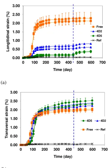
The longitudinal and transverse strains of specimens under restraint are compared with strains 119
obtained on the stress-free specimens in Figure 6. All the specimens exhibit cracks. Cracking 120
was mainly longitudinal for the restrained specimens (parallel to the restraint). Cracks seemed 121
to be wider for the specimens in stress-free conditions than for restrained specimens. The 122
longitudinal expansions show the large effect of the restraint on the strains measured in the 123
direction of compressive stress: final longitudinal expansions were only 0.6% and 0.2% for 124
the specimens restrained by steel bars of 2 and 5 mm in diameter, respectively, and 2.1% for 125
the specimens in stress-free conditions (Figure 6 – decrease of about 75 and 90%). It is 126
interesting to note that, although the relative decreases were considerable, the expansions 127
stayed quite large in the restrained direction (for the strongest restraint, the expansion was still 128
about 0.2%). DEF-induced transverse expansion showed (Figure 6-b): 129
- a slight delay (between 10 and 20 days) in presence of the restraint, 130
- faster stabilisation for the specimens in stress-free conditions (after about 250 days of 131
immersion), 132
- transversal expansions were slightly larger for the restrained specimens at 400 days 133
(before the restraint was withdrawn), with strains of about 2.2 and 2.3% versus 2% for 134
stress-free specimens. 135
Finally, the longitudinal restraint had a smaller effect on transverse strains than on 136
longitudinal strains. Moreover, all the transverse strains were measured in the two transverse 137
directions of the specimens. Little scatter was observed according to the direction. Expansions 138
in the two stress-free transverse directions were similar. 139
After the restraints had been withdrawn (442 days), the longitudinal expansions showed slight 140
increases, particularly for the most restrained specimens (Figure 6). They stabilised quickly 141
(at 540 days) and did not significantly modify the results (Figure 6-a). As specimens were 142
under compressive stresses due to restrained expansion and as DEF expansion appeared to be 143
stabilised in other specimens, the expansion increase may have been due to creep recovery. 144
No significant modifications were measured for transverse expansion (Figure 6-b). 145
3.3 Compressive strength
146
Compressive strength was measured on prismatic specimens (40x40x40 mm) at time-steps 147
chosen according to the expansions measured on the specimens (Figure 4). The evolution of 148
the compressive strength of the reference mortar and of the mortar damaged by delayed 149
ettringite formation have been plotted in Figure 7. The reference specimens showed the usual 150
increase of compressive strength with time due to continuous cement hydration. The 151
specimens that had been subjected to the heat treatment showed a decrease in strength (about 152
40%). 28 days after casting, the compressive strength was equal to 46.5 MPa. A large strength 153
decrease occurred mainly between 70 and 100 days, corresponding to the significant increase 154
of expansion (Figure 4-b), and the compressive strength reached a minimum value of 25 MPa 155
at 180 days. After 180 days, while expansion was stabilised, a slight increase could be noted 156
(the same increase as for the compressive strength measured on the reference specimens). The 157
evolution of relative compressive strength has been plotted versus expansion in Figure 8. The 158
maximal decrease (about 40%) was reached for expansion of about 0.7%. For expansions 159
higher than 0.7%, the reduction of the compressive strength appears to be stable. 160
4. Analysis and discussion
161
4.1 Chemo-mechanical calculations
162
The aim of this part is to analyse the strains of the restrained specimen by means of chemo-163
mechanic calculations, as can be done in the calculation of ASR-damaged structures [6, 7]. 164
The calculations are based on the assumption that DEF expansion can be considered as 165
imposed strain, as proposed in [27]. During the measurements, DEF expansion was isotropic 166
in stress-free conditions. For the specimens subjected to restraint, the strains were the same in 167
the two transversal directions but largely reduced in the longitudinal, restrained direction. This 168
anisotropy can have two causes: the only elastic effect of restraint and the reduction of DEF-169
induced expansion in the restraint direction. Elastic calculations performed with the 170
assumption of isotropic chemically imposed strain show that the reductions of the measured 171
strains due to the elastic effect are respectively about 10% and 40% under the restraints of 172
4D2 and 4D5. The reductions are thus lower than the reduction of respectively 75% and 90% 173
observed in the experimental results. This observation has already been made for ASR 174
expansion under restraint [28] and leads to assume that the chemically imposed strains are not 175
isotropic. ASR modelling based on the assumption that ASR expansion can be considered as 176
chemically imposed strains usually used an anisotropic coefficient to modify the imposed 177
strains according to the anisotropy of loading [29,30]. As the restraint was uniaxial, the 178
chemically imposed strains were assumed to be orthotropic to take account of the effect of 179
restraint on the expansion in each direction. They can be written: 180 = L imp T imp T imp imp ε ε ε ε 0 0 0 0 0 0 (1)
As for the alkali-silica reaction [6,7], the constitutive law of concrete damaged by DEF is: 181
(
)
(
)
c imp p c p c c G tr I G K K ε ε ε ε ε σ ) 2 3 3 2 ( − − + − − = (2)with: εpthe plastic strains matrix. 182
In this work, the mean structural compressive stresses are lower than 5 MPa and thus lower 183
than the mean compressive strength; the plastic strains εpare then equal to zero. The
184
equation (2) becomes: 185
imp c c c c G tr I G K K ε ε ε σ ) 2 3 3 2 ( − + − = (3) with: 186 ) 2 1 ( 3 c c c E K ν − = (4) and 187 ) 1 ( 2 c c c E G ν + = (5)
where Ec and νc are respectively the Young’s modulus of the concrete and its Poisson’s 188
coefficient, assumed isotropic. ε is known from the transverse and longitudinal 189 measurements: 190 = L meas T meas T meas ε ε ε ε 0 0 0 0 0 0 (6)
Boundary conditions are given by the two following equations: 191
- The longitudinal stresses in concrete are equal to the restraint stress: 192
rest c
zz z σ
σ ( )= (7)
with σrest the stress due to the threaded bar restraint. 193
- There are no transverse stresses: 194 0 ) ( ) (z = cyy z = c xx
σ
σ
(8)Therefore, the chemically imposed strains can be identified from the strains measured on 195
specimens: 196
− + + = L meas c c T meas c c c T imp K G K G K
ε
ε
ε
3 2 3 2 2 3 1 (9) − + + − = c rest L meas c c T meas c c L imp K K G K G σ ε ε ε 3 4 1 3 4 2 3 1 (10)It can be noted that the term σrest / Kc is negligible compared to the other two terms of the 197
equation (about 0.05% compared to more than 1%) in this work. 198
The volumetric chemically imposed strain is defined by: 199 T imp L imp V V ε ε 2 + = ∆ (11)
By combining equations 9, 10 and 11, the following equation can be obtained: 200 c rest T meas L meas T imp L imp K V V 3 2 2
ε
ε
ε
σ
ε
+ = + − = ∆ (12)The Young’s modulus of the concrete was equal to 31,000 MPa when restraint was imposed 201
(28 days after casting). The Poisson’s coefficient was taken equal to 0.2. In this study, the last 202
term of equation 12 (about 0.001%) is negligible compared to the measured strains (about 203
1%). In this case, it can be noted that the imposed volumetric strain is equal to the measured 204 volumetric strain. 205
4.2 Analysis
2064.2.1 Induced stresses
207The stresses in the specimens could be assessed from the longitudinal strains measured at the 208
beginning of the test and when the restraints were withdrawn. When restraints were applied, 209
the mean negative strains in the longitudinal directions were 30 and 70 µm/m for the 210
specimens under the restraint of 4D2 and 4D5 respectively. Before DEF occurred, the Young’s 211
modulus of the mortar had been measured. It was about 31,000 MPa. Mean compressive 212
stresses could thus be assessed: about 0.9 and 2 MPa for the restraints 4D2 and 4D5, 213
respectively, at the beginning of the tests. 214
Once expansion occurred, DEF expansions were restrained by the threaded bars, which 215
implied an increase of the longitudinal compressive stresses. The final stresses could be 216
assessed from the elastic strains measured in the longitudinal directions when the restraints 217
were withdrawn. Strains were 80 and 160 µm/m for the specimens under the restraints of 4D2 218
and 4D5 respectively. For DEF, as for ASR, mechanical characteristics such as compressive 219
strengths and Young’s modulus are modified by cracking induced by expansion. Young’s 220
modulus decreases as the cracking develops. The effect of restraint on DEF or ASR 221
expansions leads to cracking, mainly parallel to the restraint direction as was observed on the 222
specimens studied in this work. Therefore, it leads to anisotropic damage and the decrease of 223
the Young’s modulus is lower along the restraint directions than in stress-free directions [31]. 224
In order to quantify the compressive stresses at the end of the tests, the decrease in Young’s 225
modulus was assumed to be proportional to the decrease in compressive strength for an 226
expansion equal to the strain measured in the restraint direction (Figure 8). The mean strains 227
measured in the longitudinal direction were 0.6 and 0.2% for the restraints 4D2 and 4D5 228
respectively. For such expansions, the decreases of the compressive strength were about 65% 229
and 85% (Figure 8). For an initial value of 31,000 MPa, this led to Young’s moduli of about 230
20,150 and 26,350 MPa and thus to final compressive stresses of about 1.6 and 4.2 MPa. 231
Therefore, compressive stresses increased from 0.9 to 1.6 MPa for restraint 4D2 and from 2 to 232
4.2 MPa for 4D5. 233
4.2.2 Calculated strains
234
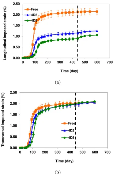
The chemically imposed strains according to the chemo-mechanical calculations performed 235
just above (equations 9 and 10) have been plotted in Figure 9 for the stress-free and restrained 236
specimens. The imposed longitudinal strains were greatly influenced by the restraint, with 237
decreases of respectively 45 and 55% for the restraints 4D2 and 4D5 in comparison with the 238
stress-free specimens (Figure 9-a). These reductions are smaller than those calculated for the 239
measured strains (75 and 90%). It is due to the elastic effect of the restraint. The imposed 240
longitudinal strains obtained for the two restraints (1.15 and 0.90% before the restraints were 241
withdrawn) are closer than the measured longitudinal strains (0.60 and 0.20% at the same 242
time – thus a factor of 3 between the measurements and only 1.25 between the imposed 243
strains). The restraints seemed to have little effect on the imposed transverse strains, with a 244
slight delay as for the measured strains, but with no differences of final strains (Figure 9-b). 245
Volumetric strains (equation 12) have been plotted in Figure 10. The volumetric strains of the 246
restrained specimens were similar (volumetric strains of about 5%) and showed a reduction of 247
about 20% compared to the volumetric strain of the stress-free specimens (6.1 % - Figure 10). 248
The effect of restraint on expansion can be quantified by the anisotropy coefficient of DEF-249
induced expansions (ratio of the longitudinal strain to the transverse strain). The assessment 250
of the anisotropy coefficients for the stress-free and restrained specimens are presented in 251
Figure 11. The longitudinal and transversal strains were highly correlated, with a correlation 252
coefficient very close to 1 for the three stress conditions. As observed in the presentation of 253
the experimental results, DEF expansions were isotropic in stress-free conditions. The 254
anisotropy coefficient was about 1.05 (Figure 11). The anisotropy of stress-free expansions 255
due to DEF was not so large as for ASR expansions, which usually present an anisotropy 256
coefficient of about 2 in stress-free conditions [22,26,32]. For ASR, the largest expansion was 257
measured in the direction parallel to casting [22,26]. For DEF, the casting direction did not 258
appear to modify expansion. The anisotropy coefficients were 0.6 and 0.45 for restraints 4D2 259
and 4D5 respectively (Figure 11). The decrease of the anisotropy coefficients quantifies the 260
decrease of the strains in the restraint direction while strains in the stress-free directions are 261
not modified. 262
Figure 12 shows the variations of the volumetric strains and of the anisotropy coefficient with 263
the final compressive stress. It illustrates the decrease of the volumetric strains by the 264
compressive stresses induced by the restraints (decrease of 20% between the stress-free and 265
the restrained specimens) and the small effect of the increase in the restraint on the volumetric 266
strain (decrease of 5% between the two restraints). The effect of the anisotropy seems to be 267
greater, with reductions of 45 and 55% of the anisotropy coefficient for the restrained 268
specimens compared to stress-free specimens. Moreover, the decrease was still large with the 269
increase of the restraint: a reduction of 25% of the anisotropy coefficient was obtained 270
between the two restraints. 271
The limit of this chemo-elastic approach is the representativeness of the chemically imposed 272
strains. The chemically imposed expansion included the delayed ettringite formation, which 273
was the real cause of expansion, and the induced cracking, which was the result of the delayed 274
ettringite formation. Moreover, such elastic calculations do not allow a determination of 275
anisotropic damage, which is observed on DEF-damaged structures and restrained specimens. 276
However, the interest of such a chemo-elastic approach is its simplicity of use for 277
experimental interpretation. 278
4.2.3 Damage and expansion
279
The decrease in the compressive strength according to expansion obtained in this work 280
(Figure 8) and results obtained by Brunetaud [33] have been plotted in Figure 13. For 281
expansions lower than 1%, the experimental results are quite close. For expansions larger than 282
1%, Brunetaud’s work shows a continuous decrease (Figure 13) while the compressive 283
strength appears to be stabilised in the present study. The differences between the two studies 284
can be explained by the different experimental conditions (types of aggregate, specimen sizes, 285
mix-design…). Moreover, at 1% expansion, the results of mechanical tests can be influenced 286
by the significant damage; for such expansion, the discrepancy for experimental results can be 287
large and comparisons are then difficult. 288
Modelling use a relationship between expansion and decrease in mechanical characteristics to 289
assess the damage due to expansive reactions [9,31,34]. The damage d can be calculated from 290
the decrease in the compressive strength: 291
( )
( )
( )
0 1 t f t f t d c c − = (13)where fc(t) the compressive strength at time t and fc(t0) the initial compressive strength. 292
As a first approach, this relationship is assumed to be similar to the relationship used for the 293
alkali-silica reaction. If the curve fitting of this relationship is difficult, another law should be 294
proposed. For ASR-modelling, Capra and Sellier proposed the following relationship between 295
expansion and damage: 296 d d − = 1 0 ε ε (14)
with ε the expansion measured on specimens with damage d and ε0 a parameter obtained by 297
curve fitting. Note that, even though equation 14 remains scalar, d can be the main value of an 298
anisotropic damage tensor, and so the chemically imposed expansion becomes different in 299
each loading direction, depending on the stress state which acts on the damage tensor 300
components [34]. 301
The proposed relationship can be fitted on the experimental results and thus gives an 302
acceptable representation of the increase of damage with expansion. The effect of expansion 303
on the mechanical characteristics of damaged concrete is difficult to generalise. For ASR, 304
some authors have reported large decreases in mechanical strength [35-37] whereas other 305
experimental works show smaller decreases that mainly concern the Young’s modulus while 306
compressive strength is not modified [22,38,39]. For ASR expansion, Capra and Sellier 307
obtained a value of ε0 lying between 0.3 and 0.6% [34]. The fitting leading to the value of 308
0.3% was based on a tensile strength test performed by ISE [35] while the compressive 309
strength led to 0.6%. Capra and Sellier kept 0.3% for the sake of safety as a small value of ε0 310
leads to an overestimate of the damage for a given expansion. The results of measurements 311
obtained for the effect of DEF expansions on the compressive strength are included between 312
two curves with ε0 between 0.6 and 2%. Prudence requires the lowest (0.6%) to be taken for 313
the effect of DEF expansion on compressive characteristics. It means that DEF expansion 314
leads to damage of mechanical properties in compression that are in the same range as ASR 315
expansion. The relationship between damage and DEF expansion (equation 14) appears to be 316
similar to the relationship used in the mechanical models employed for the assessment of 317
ASR-damaged structures [9,31,34] which could then be kept for the assessment of DEF-318
damaged structures. 319
5. Conclusion
320
The aim of this paper has been to study the mechanical consequences of DEF expansion. Two 321
aspects were analysed in particular: the effect of restraint on the DEF expansion and the 322
evolution of compressive strength with expansion. Several points have been made: 323
- DEF expansion is isotropic in stress-free conditions, 324
- Compressive stresses decrease DEF expansion in the direction subjected to restraint 325
and lead to cracks parallel to the restraint. The larger the restraint, the smaller the DEF 326
expansion. However, DEF expansion can be greater than 0.2% for stresses of about 327
4 MPa. 328
- Expansion measured in the stress-free direction of restrained specimens is not 329
modified, and thus restraint causes a decrease in the volumetric expansion (decrease of 330
20% for the restrained specimens compared to stress-free ones). 331
- Therefore, expansion induced by DEF is anisotropic in restrained conditions. The 332
differences of expansion between stress-free and restrained directions can be 333
quantified by a coefficient of anisotropy of 0.6 and 0.45 for compressive stresses of 334
1.6 and 4.2 MPa respectively. 335
- The evolution of concrete damage with DEF expansion has been quantified. 336
Unlike the case for ASR, no transfer of expansion was noted on restrained specimens and the 337
casting direction appeared not to modify DEF expansion. The differences between ASR and 338
DEF could be explained by the difference of viscosity of the chemical products formed by the 339
reactions. ASR products can migrate in the porosity and cracks after their formation, which 340
allows the transfer of gel from the aggregate to the crack parallel to the unloaded directions 341
and thus an increase of expansion in the free directions. DEF products are crystallized and, 342
once formed, cannot move so easily in the cracks. Therefore, the place where reaction 343
products are formed can have consequences on the damage process. Structural models have to 344
take account of the effect of stresses on DEF expansion to perform relevant calculations to 345
reassess DEF damaged structures and this particularity of DEF expansion should be 346
considered. Works are in progress to link the volume of ettringite produced during the delayed 347
formation with the induced expansions in restrained conditions and considering the concrete 348
damage. Thus, the data provided in this experimental study will be used for the quantification 349
of the effect of stresses on DEF induced expansion. 350
352
References
353
[1] P. Tepponen, B.E. Ericksson, Damages in concrete railway sleepers in Finland, J. Nordic 354
Conc. Res. 6 (1987) 199-209. 355
[2] C. Larive, N. Louarn, Diagnosis of alkali-aggregate reaction and sulphate reaction in 356
French structures, Proceedings of the 9th International Conference on Alkali Aggregate 357
Reaction, Concrete Society Publication CS 106, London, Great-Britain, 1992, pp. 587-598. 358
[3] A. Shayan, G.W. Quick, Microscopic features of cracked and uncracked concrete railway 359
sleepers, ACI Mat. J. 89 (1992) 348-361. 360
[4] S. Diamond, Delayed ettringite formation - process and problems, Cem. Conc. Comp. 18 361
(1996) 205-215. 362
[5] M. Thomas, K. Folliard, T. Drimalas, T. Ramlochan, Diagnosing delayed ettringite 363
formation in concrete structures, Cem. Conc. Res. 38 (2008) 841-847. 364
[6] F.-J. Ulm, O. Coussy, K. Li, C. Larive, Thermo-chemo-mechanics of ASR expansion in 365
concrete structures, J. Eng. Mech. 126 (3) (2000) 233– 242. 366
[7] K. Li, O. Coussy, Concrete ASR degradation: from material modeling to structure 367
assessment, Conc. Sc. Eng. 4 (2002) 35-46. 368
[8] V. Saouma, L. Perotti, T. Shimpo, Stress Analysis of Concrete Structures Subjected to 369
Alkali-Aggregate Reactions, ACI Struct. J. 104 (5) (2007) 532-541. 370
[9] A. Sellier, E. Bourdarot, S. Multon, M. Cyr, E. Grimal, Combination of Structural 371
monitoring and laboratory tests for the assessment of AAR-swelling - Application to a gate 372
structure dam, ACI Mat. J. 106 (3) (2009) 281-290. 373
[10] C. Comi, R. Fedele, U. Perego, A chemo-thermo-damage model for the analysis of 374
concrete dams affected by alkali-silica reaction, Mech. of Mat. 41 (2009) 210-230. 375
[11] H.F.W. Taylor, C. Famy, K.L. Scrivener, Delayed ettringite formation, Cem. Conc. Res. 376
31 (2001) 683–693. 377
[12] M. Collepardi, A state of the art review on delayed ettringite attack on concrete, Cem. 378
Conc. Comp. 25 (2003) 401-407. 379
[13] C. Larive, A. Laplaud, M. Joly, Behavior of AAR-afffected concrete: Experimental data, 380
Proceedings of the 10th International Conference on Alkali-Aggregate Reaction, Melbourne, 381
Australia, 1996, pp. 670-677. 382
[14] T. Ahmed, E. Burley, S. Rigden, The effect of alkali-silica reaction on the fatigue 383
behaviour of ordinary concrete tested in compression, indirect tension and flexure, Mag. 384
Concr. Res. 51 (6) (1999) 375-390. 385
[15] C. Gravel, G. Ballivy, K. Khayat, M. Quirion, M. Lachemi, Expansion of AAR concrete 386
under triaxial stress: simulation with instrumented concrete block, Proceedings of the 11th 387
International Conference on Alkali-Aggregate Reaction, Québec, Canada, 2000, pp. 949-958. 388
[16] S. Multon, F. Toutlemonde, Effect of applied stresses on alkali-silica reaction-induced 389
expansion, Cem. Con. Res. 36 (2006) 912-920. 390
[17] S. Inoue, M. Fujii, K. Kobayashi, K. Nakano, Structural behaviors of reinforced concrete 391
beams affected by alkali–silica reaction, Proceedings of the 8th International Conference on 392
Alkali-Aggregate Reaction, Kyoto, Japan, 1989, pp. 727– 732. 393
[18] R.N. Swamy, M.M. Al-Asali, Control of alkali–silica reaction in reinforced concrete 394
beams, ACI Mater. J. 87 (1990) 38-46. 395
[19] A.E. Jones, L.A. Clark, The effects of restraint on ASR expansion of reinforced concrete, 396
Mag. Concr. Res. 48 (174) (1996) 1-13. 397
[20] S. Fan, J.M. Hanson, Length expansion and cracking of plain and reinforced concrete 398
prisms due to alkali–silica reaction, ACI Struct. J. 95(4) (1998) 480-487. 399
[21] T.U. Mohammed, H. Hamada, T. Yamaji, Alkali–silica reaction-induced strains over 400
concrete surface and steel bars in concrete, ACI Mater. J. 100 (2003) 133-142. 401
[22] S. Multon, J-F. Seignol, F. Toutlemonde, Structural behavior of concrete beams affected 402
by alkali–silica reaction, ACI Mater. J. 102 (2) (2005) 67-76. 403
[23] G. Escadeillas, J-E. Aubert, M. Segerer, W. Prince, Some factors affecting delayed 404
ettringite formation in heat-cured mortars, Cement and Concrete Research 37 (2007) 1445-405
1452. 406
[24] N. Leklou, Contribution à la connaissance de la réaction sulfatique interne, PhD thesis, 407
Toulouse, Université de Toulouse, 2008 (in French). 408
[25] N. Leklou, J-E. Aubert, G. Escadeillas, Microscopic observations of samples affected by 409
delayed ettringite formation (DEF). Mater. Struct. 42 (2009) 1369–1378. 410
[26] C. Larive, M. Joly, O. Coussy, Heterogeneity and anisotropy in ASR affected concrete – 411
consequences for structural assessment, Proceedings of the 11th International Conference on 412
Alkali-Aggregate Reaction, Quebec, Canada, 2000, pp. 969– 978. 413
[27] N. Baghdadi, J.-F. Seignol, F. Toutlemonde, Modélisation du couplage chimico-414
mécanique pour calculer une structure en béton atteinte de réaction sulfatique interne, 18ème 415
Congrès Français de Mécanique, Grenoble, France, 2007. 416
[28] S. Multon, J-F. Seignol, F. Toutlemonde, Chemomechanical assessment of beams 417
damaged by Alkali-Silica Reaction, ASCE, J. Mat. in Civil Eng. 18 (2006) 500-509. 418
[29] V. Saouma, L. Perotti, Constitutive model for alkali-aggregate reactions, ACI Mater. J. 419
103 (3) (2006) 194-202. 420
[30] N. Baghdadi, F. Toutlemonde, J-F. Seignol, Modélisation de l’effet des contraintes sur 421
l’anisotropie de l’expansion dans les bétons atteints de réactions de gonflement interne, 422
XVèmes Rencontres de l'AUGC, Bordeaux, France, 2007. 423
[31] E. Grimal, A. Sellier, Y. Le Pape, E. Bourdarot, Creep shrinkage and anisotropic damage 424
in AAR swelling mechanism, part I: a constitutive model, ACI Mater. J. 105 (2008) 227-235. 425
[32] N. Smaoui, M.A. Bérubé, B. Fournier, B. Bissonnette, Influence of specimen geometry, 426
direction of casting, and mode of concrete consolidation on expansion due to ASR, J. Cem. 427
Concr. Agg. (ASTM), 26 (2) (2004) 58-70. 428
[33] X. Brunetaud, L. Divet, D. Damidot, Impact of unrestrained Delayed Ettringite 429
Formation-induced expansion on concrete mechanical properties, Cem. Conc. Res. 38 (2008) 430
1343–1348. 431
[34] B. Capra, A. Sellier, Orthotropic modelling of alkali-aggregate reaction in concrete 432
structures: numerical simulations, Mech. of Mater. 35 (2003) 817–830. 433
[35] R. Pleau, MA. Bérubé, M. Pigeon, B. Fournier, S. Raphael, Mechanical Behavior of 434
Concrete Affected by ASR, Proceedings of the 8th International Conference on Alkali-435
Aggregate Reaction, Kyoto, Japan, 1989, pp. 721-726. 436
[36] Institution of Structural Engineers, 1992, In: Structural effects of alkali-silica reaction, 437
technical guidance on the appraisal of existing structures. Published by the Institution of 438
Structural Engineers, London. 439
[37] S. Fan, J.M. Hanson, Effect of Alkali-Silica Reaction Expansion and Cracking on 440
Structural Behavior of Reinforced Concrete Beams, ACI Struct. J. 95 (5) (1998) 498-505. 441
[38] L.J. Monette, N.J. Gardner, P.E. Grattan-Bellew, Residual Strength of Reinforced 442
Concrete Beams Damaged by Alkali-Silica Reaction—Examination of Damage Rating Index 443
Method, ACI Mater. J. 99 (1) (2002) 42-50. 444
[39] C. Larive, Apports combinés de l'expérimentation et de la modélisation à la 445
compréhension de l'alcali-réaction et de ses effets mécaniques, Etudes et Recherches, OA 28, 446
Laboratoire Central des Ponts et Chaussées, Paris, 1998. 447
448 449
Tables
450
Table 1: Chemical compositions of cement and aggregate (%) 451
SiO2 Al2O3 Fe2O3 CaO MgO SO3 K2O Na2O Na2Oeq LOi
Cement 19.3 4.6 2.2 63.9 2.4 3.3 1.1 0. 3 1.02 - Aggregate 96.1 - 0.4 1.38 0.24 - 0.72 0.79 1.26 0.4 452 453 454
Figures
455 456Figure 1: Specimen under restraint
457 458 459
460
Figure 2: Specimen with the steel studs used for the displacement measurements in the longitudinal (L1,
461
L2) and in the transversal (T1 to T4) directions
462
(a)
(b)
Figure 3: Extensometers for the longitudinal (a) and the transversal (b) measurements
463 T2 T1 L1 L2 T3 T4
0.00 0.50 1.00 1.50 2.00 2.50 0 100 200 300 400 500 600 700 S tr a in ( % ) Time (day) Ref DEF
Figure 4: Strain of specimens in stress-free conditions (each line corresponds to one specimen, specimens
464
of a same batch are plotted with the same marker – dotted lines show the times of the mechanical tests)
465 0.00 0.50 1.00 1.50 2.00 2.50 3.00 0 100 200 300 400 500 600 700 S tr a in ( % ) Time (day) Long / DEF Trans / DEF Long / Ref Trans / Ref 466
Figure 5: Longitudinal and transversal strains of specimens in stress-free conditions
467 468
469 0.00 0.50 1.00 1.50 2.00 2.50 3.00 0 100 200 300 400 500 600 700 L o n g it id in a l s tr a in ( % ) Time (day) Free 4D2 4D5 Ref (a) 0.00 0.50 1.00 1.50 2.00 2.50 3.00 0 100 200 300 400 500 600 700 T ra n s v e rs a l s tr a in ( % ) Time (day) 4D5 4D2 Free Ref (b)
Figure 6: Longitudinal (a) and transversal strains (b) of specimens subjected to DEF in stress-free
470
conditions and under restraint (4D2 and 4D5 for the restraint by four bars of 2 and 5 mm respectively –
471
the dotted line shows the time when restraint was withdrawn)
472 473
0 10 20 30 40 50 60 70 80 0 100 200 300 400 500 Time (day) C o m p re s s iv e s tr e n g th ( M P a ) Reference DEF 474
Figure 7: Evolution of the compressive strength
475 476 0.0 0.2 0.4 0.6 0.8 1.0 1.2 0.0 0.5 1.0 1.5 2.0 S ta n d a rd is e d m e c h a n ic a l c h a ra c te ris tic % strain Rc/Rc0 477
Figure 8: Decrease of compressive strength according to DEF expansion
478 479 480
0.00 0.50 1.00 1.50 2.00 2.50 0 100 200 300 400 500 600 700 L o n g it u d in a l im p o s e d s tr a in ( % ) Time (day) Free 4D2 4D5 (a) 0.00 0.50 1.00 1.50 2.00 2.50 0 100 200 300 400 500 600 700 T ra n s v e rs a l im p o s e d s tr a in ( % ) Time (day) Free 4D2 4D5 (b)
Figure 9: Imposed longitudinal (a) and transversal (b) strains
481 482 0.00 1.00 2.00 3.00 4.00 5.00 6.00 7.00 0 100 200 300 400 500 600 700 V o lu m e tr ic i m p o s e d s tr a in (% ) Time (day) Free 4D2 4D5 483
Figure 10: Volumetric strains for stress-free and restrained specimens
484 485
Slope = 1.05 R² = 0.999 Slope = 0.6 R² = 0.998 Slope = 0.45 R² = 0.999 0.0 0.5 1.0 1.5 2.0 2.5 0.0 0.5 1.0 1.5 2.0 2.5
Transversal imposed strain (% )
L o n g it u d in al i m p o se d st rai n ( % ) Free 4D2 4D5 486
Figure 11: Anisotropy coefficients of DEF expansions under restraint
487 0 0.2 0.4 0.6 0.8 1 1.2 1.4 -5 -4 -3 -2 -1 0
Final axial stress (MPa)
D E F A n is o tr o p y 0.0 2.0 4.0 6.0 8.0 10.0 F in a l v o lu m . s tr a in ( % )
Anisotropy Volumetric strain
488
Figure 12: Anisotropy coefficient of DEF expansions and volumetric strain according to the final axial
489 stress 490 0.0 0.2 0.4 0.6 0.8 1.0 1.2 0.0 0.5 1.0 1.5 2.0 S ta n d a rd is e d m e c h a n ic a l c h a ra c te ri s ti c ( 1 -d ) % strain Fit+ Rc/Rc0 Fit- Brunetaud ε0= 0.6 ε0= 2. 491
Figure 13: Standardised mechanical characteristic (compared with Brunetaud’s work [33] and modelled
492
by Capra and Sellier’s law [34])
493 494