Capturing Graphic Design
Knowledge from Interactive
User Demonstrations
by Alan Greg TurranskyBachelor of Fine Arts
University of Massachusetts at Amherst, 1990
Submitted to the Program in Media Arts and Sciences, School of Architecture and Planning,
in Partial Fulfillment of the Requirements for the Degree of Master of Science in Media Arts and Sciences
at the Massachusetts Institute of Technology, September 1993
@ Massachusetts Institute of Technology 1993, All rights reserved.
Author Alan Turra7Tsk
Program in Media Arts and Sciences, July 15, 1993
Certified by
Ronald Ma
Principal Research Assocgte, Thesis Supervisor
Accepted by Stephen Benton
Chairperson, Departmental Committee on Graduate Students
Rotch
MASSACHUSETTS INSTITUTE
Capturing Graphic Design
Knowledge from Interactive
User Demonstrations
by Alan Greg Turransky
Submitted to the Program in Media Arts and Sciences, School of Architecture and Planning on July 15, 1993 in partial fulfillment of the requirements for the degree of Master of Science in Media Arts and Sciences
at the Massachusetts Institute of Technology.
Abstract
The abundance of layout problems commonly associated with the presentation of visual information on computer displays necessitates that computer systems be incorporated with graphic design knowledge to effectively and intuitively aid users in presenting, customizing , and
organizing this form of data. Current methods of encoding such knowledge requires that human designers verbally translate their expertise into a set of programmable rules, frames, cases, or constraints. Computer systems which can be trained to learn the techniques designers use to effectively present visual information, by having a designer demonstrate their application on a working example may provide a more natural means of translating this type of knowledge from its original visual form into the electronic environment, without the necessity to first translate it into a textual representation.
This thesis describes a system which uses a machine learning technique called Programming by Demonstration to overcome this translation problem and enable the transformation of visual ideas into usable symbolic forms. It offers a working model, called the Abatan system, for capturing re-usable, graphic design knowledge from interactive user demonstrations.
Thesis Supervisor: Ronald MacNeil, M.F.A. Title: Principal Research Associate
This work was sponsored in part by the Alenia Corporation, the Joint National Intelligence Development Staff, and the Kansa Corporation. The views and
conclusions in this document are those of the author and should not be interpreted as necessarily representing the official policies, expressed or implied, of the Alenia Corporation or the Joint National Intelligence Development Staff.
Capturing Graphic Design
Knowledge from Interactive
User Demonstrations
by Alan Greg TurranskyThe following people have served as readers for this thesis.
Supervisor
Ronal MacNeil, M.F.A. Principle Research Associate
Visible Language Workshop, Massachusetts Institute of Technology
Reader A Russell A. Kirsch, S.M. Director of Research Sturvil Corporation Reader
~~-~..
William L. Porter, Ph.D.Muriel and Norman Leventhal Professor of Architecture and Planning Department of Architecture, Massachusetts Institute of Technology
Acknowledgments
Several people have contributed to this work in many ways; writing computer code, giving advice and suggestions, and providing general overall support. I wish to thank:
Ron MacNeil Russell Kirsch Bill Porter Muriel Cooper Louie Weitzman B.C. Krishna Maia Engeli John Grabowski Bob Sabiston
For being my supervisor and pushing me to describe the subject matter in this thesis using illustrations more than words.
For providing challenging questions and detailed responses, not to mention being such a wonderful source of inspiration.
For truly being interested in the design process and the nature of design.
For hard-pressed questions and providing a stimulating environment with lots of fun toys to play with.
For suggestions, advice, and always keeping in perspective what research should be about; not to mention helping with the Output Mechanism.
For being honest, playing devil's advocate, and taking lots of breaks; not to mention writing the text library.
For always seeing and putting emphasis on the design rather than the computer, regular shipments, and help on the example scenario chapter.
For providing me with and teaching me about all of the fun and wonderful UNIX toys.
For answering all of my BadWindows questions, lots of free movie passes, having such a great music selection, and for being such a wonderful late night working partner.
Alice Lei Laura Scholl Amy Freeman Linda Peterson Dave Small Fellow Graduate Students Henry Lieberman David Kurlander David Maulsby Louis Silverstein Beverly Woolf Ray Lauzzana Leo Degen Deb and Sean
Mom and Dad
Jay
For being the other black sheep of the family with me.
For saying those three little words to me early on which truly said it all ... "its not you."
For a wonderful ear, a warm heart, and for putting up with everything (you deserve better).
For everything.
For being Dave Small.
Suguru Ishizaki (for wonderful advice and suggestions on the Graphical History, object movement, and ideas in general), Steve "Stone" Librande (for explaining C in real world, easily understandable terms), Grace Colby (for emphasizing the design before the computer), Didier Bardon, Michelle Fineblum, Craigie, "K," and Jeff.
his interest in Programming by Demonstration.
advice and suggestions on the Graphical History.
advice and suggestions in general.
advice on how we go about designing.
first suggesting that I come to the Media Lab.
For being my true advisor and friend over the years.
For knowing all along what it was all truly about. Hou je Taai!
For eventually giving me a niece or nephew whom I can quickly hook up to a computer.
For never questioning and always supporting my educational decisions, and for never making me truly explain to them what it is I actually do.
For putting up with my long absence and for (believe it or not) being a wonderful source of inspiration.
Table of Contents
chapter 1.
Introduction
10
Motivation 11
Approach 15
The Title Example 17
Scenario 19
Document Structure 22
Definitions 22
chapter 2.
Related Research
24
Designer: A Knowledge Based, Graphic Design Assistant 25
Liga: Intelligent Layout for Information Display 26
Tyro: The Case Based, Graphic Designer's Apprentice 27 Metamouse: Specifying Graphical Procedures by Example 28
Mondrian: A Teachable Graphical Editor 29
Chimera: Graphical Editing by Example 30
chapter 3
Overview of the Project
31
The Name "Abatan" 31
System Capabilities and Components 32
Selecting an Example 33
Building and Describing the Example Layout 34
Encoding the Knowledge 37
Testing the Knowledge 39
The Table of Contents Example 40
chapter 4.
How It Works
46
Graphical Objects 47 Knowledge Base 53 Lexical Knowledge 53 Lexicon Palette 55 Grammatical Knowledge 56 Exemplar Layout 60 Recording Mechanism 61 Graphical History 63 Learning Module 65 Generalization Editor 65 Generalization 69 Output 74 Re-Application 74 Computer Code 77Mechanics and Resources 81
chapter 5.
Scenario
82
chapter 6.
Conclusion
98
Future Directions 99
Summary 101
Appendices
102
Visual Examples of Design Knowledge 102
Symbolic Examples of Design Knowledge 112
List of Figures
chapter 1.
Introduction
10
1 .1 The direct translation of visual rules into symbolic form. 11
1.2 Applied design principles. 12
1.3 Weitzman's Design Support system, the Logic of Layout. 1 3 1.4 Techniques used to emphasize a "title." 15 1.5 A "title" object formatted with simple design rules. 17
1.6 Hierarchical structure of a layout. 18
1.7 Anchor objects of a layout. 18
1.8 Re-application of "Title" rules to new arguments. 21
"Title" example action sequences. 19 - 21
chapter 2.
Related Research
24
2.1 Weitzman's Designer. 25 2.2 Colby's Liga. 26 2.3 MacNeil's Tyro. 27 2.4 Maulsby's Metamouse. 28 2.5 Lieberman's Mondrian. 29 2.6 Kurlander's Chimera. 30
chapter 3.
Overview of the Project
31
3.1 The Abatan Design Environment. 31
3.2 Schematic diagram of the Abatan system. 32
3.3 The color and font palettes. 34
3.4 The Lexicon palette. 34
3.5 The Exemplar Layout. 35
3.6 The Graphical History. 37
3.7 The Generalization Editor. 38
3.8 A table of contents formatted with seven design rules. 40 3.9 The "Bottom," "Left," and "Right" aligning actions. 41 3.10 The "Equal Color" and "Equal Font" actions. 42 3.11 Graphically altering elements to reflect system interpretation. 43
3.12 The Generalization Editor. 44
3.13 The "Table of Contents" domino icon. 44 3.14 "Table of Contents" layout before rules have been applied. 45 3.15 Re-applying the "Table of Contents" rules to new arguments. 45
chapter 4.
How
4.1 4.2 4.3 4.4 4.5 4.6 4.7 4.8 4.9 4.10 4.11 4.12 4.13 4.14 4.15 4.16It Works
The "encoding" pipeline. Symbol class hierarchy.
Symbols in Abatan are a three-part structure.
The nine touch sensitive "hot spots" of a graphical object. Three different states of the Lexicon palette.
The grammatical knowledge base default-settings look-up table. Three different states of the Exemplar Layout.
The ACTION structure.
Menu selection and direct manipulation editing of a panel. The Generalization Editor.
Visual manipulation editing of a recorded action. "Sending" an action panel to the Editor.
"Before" and "After" generalization states of an action. A domino icon.
An Output Mechanism lexical action look up table. The LOLactionnamelookup function.
chapter 5.
Scenario
5.1 A current Scientific American table of contents. 5.2 The Scientific American "Table of Contents" domino. 5.3 The "before" state of a new Scientific American entry. 5.4 The new entry after applying "Table of Contents" rules. 5.5 Re-application of the rules after changes have been made. 5.6 Further re-application of the rules to adapt to a new situation. 5.7 Partial re-application "before" state.
5.8 Partial re-application "after" state.
5.9 A newly formatted Scientific American table of contents. 5.10 Outputted rules from the Scientific American example. 5.11 Automatic generation of a new table of contents. Storyboard sequence.
Appendices
Layout 1, Version 1 Layout 1, Version 2 Layout 1, Version 3 Layout 1, Version 4 Layout 1, Version 5 Layout 2, Version 1 Layout 2, Version 2 Layout 2, Version 3 Layout 2, Version 4Layout 1, Rule and Constrain Function Layout 2, Rule and Constrain Function
46
46 47 48 50 54 59 60 62 64 66 67 68 69 74 79 8082
82 91 92 92 93 93 94 94 95 96 97 83 - 89102
103 104 105 106 107 108 109 110 111 112 113chapter 1.
Introduction
Abatan is an interactive design environment which allows designers to graphically create, manipulate, and describe page-layouts. During the design process, the system monitors how the designer assembles the layout. As the designer alters and conforms graphical elements in the layout, the system records the actions performed and directly translates these into generalized computational descriptions that can be re-used to format new elements in a similar style. The goal of the system is to directly translate visual knowledge into a symbolic form (computer code)
so that it may be utilized by other existing design programs to aid users in creating new layouts.
This prototype system has been developed to provide visually oriented users with a tool to graphically encode their design knowledge into a symbolic representation, without the necessity to first translate it into a verbal or textual form. Abatan differs from existing macro systems and programs which allow users to graphically define templates, in that the knowledge stored is generalized, allowing for re-application in a manner which maintains the logical structure of the information, but is capable of
adapting to new configurations. The system provides two major
advantages over existing programs. First, the user is able to encode, edit, and re-use the knowledge they wish to convey, graphically, and second, the encoded knowledge can be output in a symbolic form which other
existing design systems can utilize.
This thesis describes the design and implementation of the Abatan program and illustrates several examples of the system at work capturing graphic design knowledge from interactive user demonstrations.
In the past decade, technical advances have made the process of creating, manipulating, and transferring data extremely easy and quick. News information can be sent around the globe via satellite and televised onto a personal computer's display in a matter of seconds. Legal documents can be drafted, edited, and faxed in half the time it took only a few years ago, and multimedia presentations and hypertext documents can be customized to meet individual user needs and requirements. In order to enhance computer-human communications for a wide range of users, computer systems must be able to present information to the user in an easily understandable and comprehensible manner, which usually results in interacting with the data graphically.
Figure 1.1. The goal: The direct translation of visual rules into symbolic form.
In static media such as newspapers and magazines, it has traditionally been the job of a graphic designer to take the data and present it in a form which satisfies necessary communications goals, such as ensuring that the information maintains legibility, formatting certain aspects to emphasize importance, and so on (figure 1.2). Over the years the field of graphic design has developed a rich set of solutions for solving a wide range of visual communication problems, but unfortunately the amount of information used today is too overwhelming for a human designer to customize each and every document [Colby 92].
max digits number of digits phone number current position #define
int
PNMAX char main(argc, argv)int
argo
char *argv[]; register intbool foundvowel = FALSE;
F phone rgument ...
while (*++argv != NULL) if (!getpn(*argv))
fpintf(stderr, "PhoneName: %s isn' t a phone number\n", *afW);
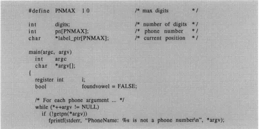
Figure 1.2. Design principles can be applied to re-enforce and emphasize portions of a layout. Even simple techniques such as changing typefaces, point sizes, and styles can make a difficult design easier to read (Reprinted from [Marcus 921).
10 digits; pn[PNMAX];
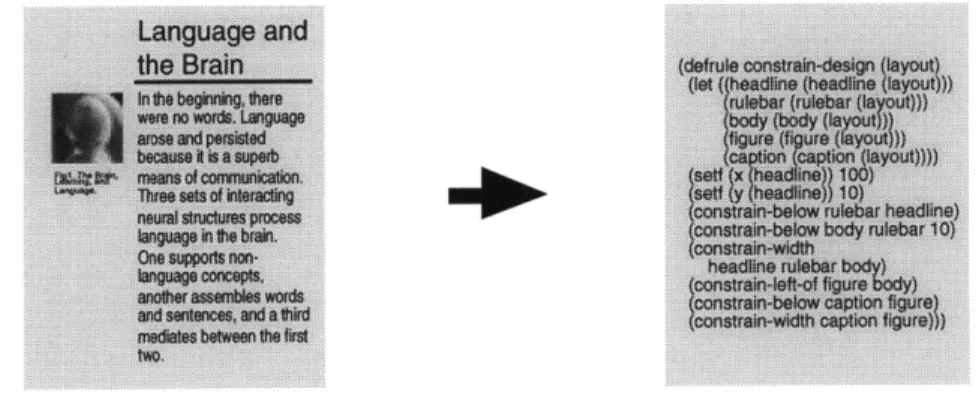
Currently, research in the fields of Automatic Layout and Design Support attempts to create computer programs, encoded with graphic design knowledge of how to format information, to aid novice users in easily creating high quality, professional looking visual layouts ([Colby 92] [Feiner 88] [MacKinlay 87] [MacNeil 90] [Marks 90] [Weitzman 88]). Weitzman's Design Support system, the Logic of Layout [Weitzman 92] contains a knowledge base which describes stylistic relationships among elements commonly found in the layout of Scientific American articles. Users of the system construct new Scientific American layouts by roughly sketching in objects, such as headlines, images, and captions without concern for fine detail. The system performs inferencing on the partially inputted data to determine relationships between the objects. After identifying such, it automatically applies constraints to format the design, changing typefaces, point sizes, and positioning to produce a layout which adheres to the magazine's uniform style.
Figure 1.3. Weitzman's Design Support system, the Logic of Layout, uses
inferencing to determine relationships between graphical objects, such as the image and a caption shown above, and automatically applies constraints to alter their attributes to conform to a specific style.
As can be seen in figure 1.3, when creating a layout which contains an image and a caption, the system automatically combines the two to create a composite object that functionally acts as one. In the process, the caption's width is constrained to equal that of the image's and its position altered to
reflect that found in the magazine, not requiring that the user format these individual attributes.
While the importance and growing need for computer programs to be incorporated with graphic design knowledge (to aid users in effectively presenting visual information) is apparent, until recently, little emphasis and support have been placed upon the problem of actually encoding the knowledge into the computer. The primary method of encoding involves several non-trivial steps, most of which are non-intuitive to a visual designer. To incorporate the knowledge used in these systems a human designer must identify the relationships and problem solving techniques exhibited in existing layouts, verbally translate these into a textual description, and then hand this off to a programmer who encodes it into a symbolic form, such as a set of rules, cases, or constraints. Unfortunately these steps contain implicit variables which make the process extremely time consuming, error prone, and shallow in re-application scope, only enabling knowledge from context specific domains to be conveyed. For example, without further programming Weitzman's Logic of Layout is only able to support the creation of Scientific American articles, even though the individual rules which govern the layout, if generalized, could be used to format new layouts in different domains.
Computer systems that can be trained to learn design techniques through demonstration of their application on a working example may provide a more natural means of translating this knowledge from its original visual form into the electronic environment. This thesis describes an alternative model to the current method of verbally encoding design knowledge, that uses a machine
learning technique called Programming by Demonstration [Cypher 93]. Programming by Demonstration allows users to program a system in the same manner a teacher might instruct a student; by presenting a problem task
and illustrating the sequence of operations needed to solve the task on a working example. When Programming by Demonstration is used to teach graphic design, problem tasks and their solutions are communicated through the creation of example layouts. The actions used to format the layout and the results obtained are generalized to produce a working computer program
that can be applied to solve similar layout problems. In the case of
Weitzman's Logic of Layout, the rules used to constrain the image and caption in the previous figure could be illustrated simply by graphically manipulating the objects' attributes until they conformed into the final state which satisfied the rules.
APPROACH
Arts / Entertainment
Abatanis aninteracivedesig The prlot systrhas program that atows users to developed to Wle no graphcally noede, manputde, oteded, posbly roo an dese pagstalinab cahi tater coneptfe toaice, user togrpte t h d o eydmnottr a the ttr atoer exigtba
th up m o t h a tre
toe user coates a laput. As t tratito n the user alers and cotforms annal torm. Abatad
objets in the layo, the on eacteg maro rye
psotot s an a traniat togaphoetydefn tamp
these in a genaize to
can be re-ap~fed to formal appboatot era new informdion in a stoarmtainthealogalteo
style as toat presanted or toe but a capable ot edoypt
sexatfists. ntrcantitguratoas.
S rts/'E ntertainment
brer Athatatos anontraoboadesigt Thegc, taynterhaaebsan
luatty ponger theallowe useos to do opal to a ,o otoIV
puer graphbak de, marputeb, orerted, possib omter
kfeety and dert page4Wou roviteusers to grphssi
org isolo
Iate ihtate cornpt. Thed
reolo sore system ore oe entre aid , in a ymb fle fty to daag process, wtcthng horn I... rthaut the reasitYO to
at or tha e si onate a layout As firet trae r R o 0 a t verbal or htte the user atore and ootorros textuat onto. Abatar difters temo objects ioo toe layod, toe trort errinig macro system;
U 3 system records the adons andipograrnsw hbhatow
ate.% pOto n and traAb desatis to gaapnteallYdcv adais these fro a geraze inthatbttekraedgestoed a
r e onoputaternal desoptbn flat geneotfoa,nalltang for ro.
ehich oc r ao pla r a m ner
oboe, n o rmM cogiaat i Inaew e to t ure,snl mi ar rtatths th satlua g to stye the aperadsptin t preseled the but to
aeo .me etrcoafthe
Arts / Entertainment
Abatanisanintaavodesig Thepm ,yn hasbeer
c h trato s eto de e e
dprom a cn oil to.1
goaphea sr tes malaput.ab, ored, posbty omputer
e dM s raaphlratpe-eyoub noae, user to etohttsthatea yout The tanslate heirdasgnoei
es srm r ontnd toe etto ard e s Orb a ym t d atosnscritoh to, t eay
heus in teaan t. As irsttransateitnoa orbalor
to ser ala pertd rn r s terba orm. Abatat diftes objectsn h e layou, the from deg otero sydtgms
eystem records toe adcton ardptogte a sho h atnusers
pttad and tardate to goap i tydefisne lemoate%
hess orb a generalmze n that the knoiege stored s
noorputatoral dertrtat genreale, attoetog too e
a
be re-apffed to totd apiboatn ataner Mih
raw intormadion in a sir matns the logicat strucure, style as that peserttsointthe but apair of adoipting to example. n configutins.
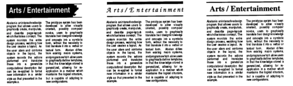
Figure 1.4. Visual examples of techniques used to emphasize a "title."
Even as far back as the cave drawings at Lascaux, pictures have been one of the most effective, universal forms of communication [Jansen 77]. We use pictures to convey messages, present ideas, and visualize abstract data. When giving complex directions we typically draw a map rather than write out the steps, to provide a greater understanding. In short, a picture truly is worth a thousand words.
While the ability to interpret drawings is not difficult, the ability to effectively convey or teach this form of "knowledge" is not so easy. Artists and designers often find that it is extremely difficult to verbalize what they are doing, mainly because their native mode of interaction centers around visual, not verbal means of communication; where knowledge is gathered and expressed through observation [Anderson 79]. When novices are being taught how to "speak" the language of design, they do so not by memorizing rules, as is the case with both written and spoken languages, but rather, they are shown example designs and watch how other more experienced designers create them. For this reason visual critique sessions and apprenticeships are an integral part of design training. This approach to learning is commonly characterized as "learning by example" or "learning by demonstration." Knowledge is expressed via examples which embody the rules that describe the knowledge, such as those found in figure 1.4.
Below we see several examples of techniques used to emphasize a "title." Note that no verbal or written explanation need accompany these layouts to describe them; the visual representation is fully capable of providing all
In order to test the "by example" idea, the Abatan system was built. The system uses the Programming by Demonstration technique to monitor the designer's activities throughout the design process and automatically translates the graphical actions performed into a usable symbolic form. The interaction dialog consists of the designer demonstrating design rules by performing the sequence of steps needed to solve a specific design problem on a concrete example. The application focus of the system centers
around designing page-layouts.
The type of design knowledge encoded deals with the lower-order rules which specify constraint relationships among graphical elements found in the layout. These relationships are the building blocks which are necessary in order for high-level concepts to operate. For example, if the idea is to have a "dominant structural order" in the layout, then the rules which constrain spatial and dimensional attributes of the graphical elements must be described before the concept can work. The Abatan system focuses on encoding such rules.
The goal of the system is three part. First, the designer should be able to encode knowledge into the system simply by creating a layout which exhibits the necessary rules. Second, the designer should be able to create and access the knowledge encoded to aid them in their work, while they are working and in a manner which minimally intrudes on the design process
itself. Finally, the system should be able to output the knowledge in a symbolic form for re-use in other existing design programs.
THE TITLE EXAMPLE
Figure 1.5. A "title" object formatted with simple design rules.
Since this thesis focuses on learning by example, the best way to discuss the system is with a demonstration. The following section presents a short
example scenario of capturing the simple design knowledge used to format the objects found in figure 1.5. In this example, the theme to be conveyed
is that of emphasizing a piece of text by placing a rulebar of the same width, height, and color directly underneath it, drawing more attention to it than if it had been placed in the layout by itself. The rules which describe the various relationships between the individual elements in the layout are taught to the system by physically manipulating their attributes until they
conform to a final state which satisfies the rules. For this example the targeted rules to be defined are as follows.
1. The rulebar's top edge should be aligned to the text's baseline. 2. The rulebar's left edge should be aligned to the text's left edge. 3. The rulebar's width should equal the text's bounding box. 4. The rulebar's height should equal the text's body-height. 5. The rulebar's color should be the same as the text's.
In addition to figure 1.5, the above rules (with the exception of number 4) describe the various constraints that were used to layout the chapter titles of this thesis, as well as the captions present in the appendices. When this document was created it was constructed in a program that allowed this author to graphically define these rules, but unfortunately did so in a "macro-like" manner. This required that two sets of rules be defined, one for the chapter titles and another for the appendices captions, even though if generalized, these rules could be used to format both. In Abatan, users can teach the system the basic, general idea defined by these rules using a single example and in return encode the necessary information to be able to layout both the titles and the captions in the same style.
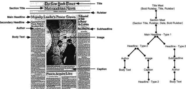
Section Title Main Headline Secondary Headline Author Body Text Title .. Rulebar 'A4le 4- Subheadline Image - Caption Title Mast (Bold Rulebar, Title, Rulebar)
Section Mast
(Section Title, Rulebar, Date, Bold Rulebar)
Main Headline - Type 1
Headline - Type 2 Headline - Type 2
Author Image Subheadline
I ge
Body Text Caption Author
Headline - Type 2 Body Text
Figure 1.6. Hierarchical structure of a layout.
Before illustrating the following scenario several details about the structure of the knowledge to be encoded must be explicitly stated. Traditionally, the individual visual elements which comprise a layout are often structured hierarchically. In the layout of the New York Times newspaper (figure 1.6) the top "node" of the hierarchy tree is the title "The New York Times," from which other "child nodes," such as headlines, base their attributes off of (figure 1.7). As will be seen later in this thesis the top node serves as an anchor point in which to base relationships. Appropriately enough, when conveying design knowledge in the Abatan system anchor objects are initially
selected as the starting point. In the following example the text will serve as the anchor object, from which the rulebar's attributes will be dependent.
Tile serves as the overall default _____________U
~
j ianchor point for the entire layout. i ItAe
it
Secton Titles vertical and
horizontal based on the Titles positions are determined ~e~r
ie
Main Headiine'a position andace termine secondary headline attributes.
Secondary Headlines' position, color, and typeface are relative to the headline they describe. Image is vertically anchored off the main headline and horizontally anchored off the body text.
- +
Maority Leader's Power Grows
Weal, VOWkis
k5nL
4 Figure 1.7. Anchor objects of a layout.
SCENARIO The interaction sequence begins by creating the text and rulebar objects and roughly placing them into the layout. Since the text will serve as the anchor object, it is selected first. The first relationship which needs to be
illustrated is that the rulebar's top edge should be aligned with the text's baseline, which in this case just happens to be its bottom edge. As will be described later in more detail (in chapter four), graphical objects within Abatan have nine touch sensitive hot spots; their four edges, four corners, and center. When an object's hot spot is clicked, it informs the system that there is something important about that point and it should look for a
possible, future relationship involving it. For this relationship, the targeted hot spot is the text's bottom edge, since the rulebar's position will be dependent on it. After selecting the text's bottom edge the rulebar's top
edge is clicked on (to point out its hot spot) and the object is dragged to a position directly below the text to illustrate the first of the four relationships stated above.
Next the designer must illustrate the relationship of left alignment between the objects. Again the text is selected first as the anchor and its left edge is touched as the hot spot. The designer then clicks on the rulebar's left edge and drags it over to be roughly aligned with the text's left edge. The designer need not precisely align the two objects, since Abatan
incorporates the notion of semantic gravity points [Lieberman 93a] which allows for tolerance and provides a more fluid type of interaction.
MMIMMML-Now that the objects are in their appropriate positions, the designer proceeds to illustrate the width relationship by clicking on the rulebar's lower right corner and resizing the object to the same width as the text's bounding box, during which time the text is still selected as the anchor object. Since we are describing relationships in a computational
environment, certain attributes can be determined based on the information provided. For example, in traditional design the above relationship could never exist since the notion of a bounding box is local to computers. Instead this would be replaced by stating that the rulebar's width should equal the literal string's width or is based in a grid's column width. In Abatan, the designer is not restricted to using only those conventions found in traditional design. For the above relationship, any of these means of specification can be used.
The final dimensional relationship to be shown is that the rulebar's height should equal the text's body-height. This relationship is specified in almost the exact manner as the width relationship; by resizing the rulebar's height to equal that of the text's.
Finally, the two objects are colored the same color by making a new selection in the color palette to state the last relationship.
Rather than arbitrarily record each individual action performed, Abatan uses a grammar to determine whether an action is legitimate enough to record based on the rules which describe the distinct emergent properties associated with each object. After the demonstration is completed the system generalizes the information stored in these recordings and produces symbolic rules which both describe the relationships stated above and are capable of formatting new "titles" in a similar style. As can be seen in figure 1.8, when the rules are applied to new arguments, only those attributes which the relationships affect are altered, but in a manner which adapts to the new situation, the rulebar's position and dimensions are now relative to the new title's, as is its color, but the text's typeface and point size remain as is.
DOCUMENT STRUCTURE' DEFINITIONS Anchor: Automatic Layout: Bounding Box: Case Base Learning: Class: Constraints:
Reference object or point in which another object's attributes are dependent on.
Area of graphic design and artificial intelligence research which focuses on the automatic generation of layouts containing text and image information for computer displays based on constraint rules which define specific styles of layouts. The smallest rectangular region which encompasses an object or group of objects in a layout.
An artificial intelligence problem solving methodology which makes decisions by adapting previously defined example problems, called cases, and applying these to solve new problems which have similar features.
A group of similar objects that share common behaviors and general characteristics.
A method of specifying values as relative relationships rather than as absolute numbers. These relationships are declared once and then maintained automatically. Constraints are often characterized by their ability to establish relationships (spatial, dimensional, typographic) among objects and their quality of suggesting relative connections between the objects. This thesis is arranged into several different sections. Chapter two
describes related research, highlighting work from the fields of Programming by Demonstration, Case Based Learning, Design Support, and Automatic Layout. Chapter three briefly gives an overview of this project and
presents a second example scenario of capturing graphic design knowledge from a user presented example. Chapter four is the heart of this document. It describes, in detail, the different components of the Abatan system, their functionality, and purpose. Chapter five presents a final detailed scenario example and chapter six concludes this document with a discussion of future directions of capturing design knowledge and a brief summary of this thesis. Finally, appendices illustrating visual and symbolic examples of design knowledge are presented.
Since the subject matter contained within this thesis covers aspects from several different fields, the following section is presented to define and clarify research specific terms that will be used throughout this document. While all terms described below are formally defined within the body of this thesis, they are initially presented here for clarity and quick reference.
Demonstrational Techniques: Design Support: Example Based Programming: Felicity Conditions: Generalization: Graphical Histories: Instructible Systems: Lower-Order Rules: Macro: Message: Method: Page-Layout: Programming by Demonstration:
Techniques with which to construct abstract computer programs by performing actions on concrete example objects [Cypher 93].
Area of design and artificial intelligence research which deals with supporting the user during the design process.
When computer programs are written through the use of user presented example data rather than conventional testing and debugging of textual programming languages [Ellman 89]. Standards necessary for a human teacher to successfully instruct a student [Maulsby 92].
The process of stripping away of example specific detail to produce, convert, or replace absolute items, such as numerical values, with abstract representations.
Connected, linear, sequential, thumbnail illustrations which represent a history of events, usually pertaining to user actions in a computer program.
Computer programs which generalize user presented information and automatically create symbolic routines, rules, or constraints.
Spatial, dimensional, and typographical rules which state specific constraint relationships among graphical objects found in a layout.
A small, user defined, program used to automate an exact series of actions or processes.
A request sent to an object to change its state or return a value. A function which automatically implements a desired response when a message is sent to an object.
The static presentation of textual and pictorial information to effectively communicate a message or idea. Good page layout is often characterized by its ability to link the visual structure of the information to reflect or enhance the content structure, in addition to making it perceptually legible and visually pleasing [Colby 92].
A subclass of Example Based Programming. A methodology for programming in which programs are written via the use of example data. Commonly, Programming by Demonstration systems learn how to perform a task by watching a user demonstrate the sequence of actions needed to execute the task on a working example. The system traces the user's input/output actions, infers information from these traces, and generalizes this into a high level function which can be used to solve new tasks [Cypher 93].
chapter
2.
Related Research
The problem of encoding and using various types of design knowledge to aid users in their work is one which has been investigated from many different angles. Most of this related research focuses on creating systems which use the knowledge to support the user while designing and not so much on the process of actually capturing it. While these systems all deal with "graphical" knowledge, their primary target domain focuses on general graphical editing tasks and the presentation of technical information such as charts and diagrams (as opposed to focusing on typographic and pictorial information found in page-layout). One of the reasons for this is that the conventions used in page-layout are not as well defined and structured as they are in other types of layouts, such as technical layouts. Technical layouts often follow a format which falls within a strict formal boundary, with distinct well defined rules making it an attractive problem set to work with. While within one style of page-layout there can and often does exist strict conventions which can be captured, the formal structure between page-layouts commonly differs from one design to the next.
There are three main areas of research that have close ties with the problem of encoding graphic design knowledge; these are: Design Support, Automatic
Layout, and Programming by Demonstration. Research in Design Support and Automatic Layout does not focus so much on encoding, but rather on how the knowledge is re-used to aid in the design process, with specific emphasis on the quality and authenticity of the knowledge. Programming by Demonstration on the other hand deals more with the encoding aspect, but unfortunately has often fallen short on quality and detail, producing only general knowledge which is not satisfactory or robust enough to offer any serious support in designing page-layouts.
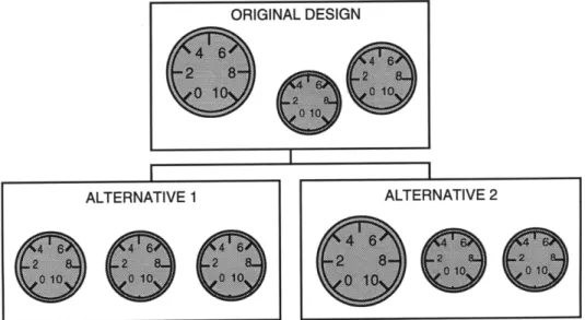
DESIGNER: A KNOWLEDGE BASED, GRAPHIC DESIGN ASSISTANT
Weitzman's Designer [Weitzman 88] is one of the first Design Support systems to deal with problems commonly found in two dimensional layout design. The system critiques the design of graphical interfaces used as front-ends to instructional computer systems and offers designers of such interfaces alternative layout configurations to their designs (figure 2.1). The alternative suggestions are based on design contexts and styles defined in the system's knowledge base and attempt to improve the design by making it more visually effective and consistent with other related interfaces. The design knowledge used in Designer is based on visual communication principles [Cheatham 83] which link visual relationships to content relationships. For example, if two elements of the design are significantly different in function or meaning, Designer attempts to produce a visual representation which is also significantly different.
Figure 2.1. Weitzman's Designer system critiques the layout of instructional interfaces and offers the user alternative solutions to their design.
The system's design knowledge is stored using a frame based [Minsky 85] representation facility and is applied to and maintained in the design using constraints. While these constraints are used in the design of technically oriented layouts, their definition and representation are based on general design principles found in the visual arts [Wong 72], graphic design
[Hurlburt 771 [Bertin 83], and architecture [Ching 791 [Sherwood 811. ORIGINAL DESIGN
LIGA: INTELLIGENT LAYOUT FOR INFORMATION
DISPLAY
Colby's research in Automatic Layout places heavy emphasis on the type of design knowledge needed to effectively present visual information on a computer display. Her system, Liga [Colby 92], automatically generates presentations of text and image information using a case-library [Riesbeck 89] to make design decisions based on the layout content structure of previously defined layouts. It dynamically adapts and re-configures a layout as environmental variables, such as the display's dimensions, change to ensure that the information maintains its legibility and logical semantic relationships (figure 2.2).
Figure 2.2. Colby's Liga uses knowledge of the problem solving techniques exhibited in existing page-layouts to dynamically adapt a computer display's layout
when environmental variables change, rather than simply reducing or enlarging the entire layout.
The graphic design knowledge stored in Liga's case-library is defined by human analysis of the problems solving techniques used in existing page-layouts (i.e., the current method of encoding). The analyzer identifies these techniques and translates them into a set of programmable constraints.
Sets of constraints which describe the stylistic relationships that govern the look of an individual layout are grouped together to form a case. Each case in the library is stored as a textual description of visual objects and their relationships to one another, and states how far these relationships can be bent before legibility of the information is lost.
TYRO: THE CASE BASED, GRAPHIC DESIGNER'S APPRENTICE
Similar to Colby's Liga, MacNeil also represents and stores design knowledge as cases in his program Tyro [MacNeil 90]. MacNeil's
philosophy for using cases is modeled after the fact that people solve a task by adapting an existing case (learned from previous experience) and applying it to the problem at hand. Tyro, a case based reasoning system,
uses this methodology to aid a designer in the presentation and revision of technical designs. MacNeil defines a model of the design process and
incorporates this into the system to control the design decisions made. The design process is classified as: 1. Making a decision; 2. Testing the decision
by creating an example layout; 3. Critiquing and revising both the layout and the reasoning processes that went into creating the layout; and 4. Evaluating and fine tuning the generalization process devised for the given task. Each case in the system's library is composed of a sequence of steps
illustrating how to resolve a single, specific type of layout problem (figure 2.3) and contains a condition-action rule which describes the circumstances surrounding the use of the case.
Figure 2.3. MacNeil's Tyro uses a case based library to aid in the design, presentation, and revision of technical layouts.
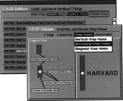
METAMOUSE: SPECIFYING GRAPHICAL PROCEDURES BY EXAMPLE
Maulsby's Metamouse [Maulsby 921, a Programming by Demonstration system, is one of the first successful attempts made at capturing graphical knowledge from a user presented example. With the system, users define and perform graphical editing tasks by instructing a turtle named Basil, "coaching" it through example executions of the task. The turtle observes the user's actions over time and performs localized analysis of changes in spatial relationships between objects in order to isolate constraints. A constraint, such as having one object's width always equal that of another, is encoded by performing multiple resizing operations to the second object each time the first object's dimensions are changed. Once such a
constraint is found, the system attempts to predict and perform future actions (figure 2.4) by creating a customized, iterative procedure to ensure that the constraint is maintained.
The innovative importance of Maulsby's Metamouse was to allow users to define new procedures to aid them in performing tedious graphical editing tasks while they were actually designing and in a manner which minimally interfered with their interaction. As will be described in the next chapter, Abatan uses the same learning approach as Maulsby's Metamouse. This approach is based upon the notions of felicity conditions [van Lehn 83] which describe rules of interaction for human teachers to effectively instruct pupils. The four conditions are defined as: 1. Show all steps of the procedure; 2. Do all steps correctly; 3. Make all invisible objects and
relationships visible; and 4. Introduce, at most, one new branch per lesson. The system incorporates an internal model of these conditions and uses it as a basis for learning.
I recognize this step. OK Heading UP?
Let me take over? M GD
Figure 2.4. Maulsby's Metamouse performs localized analysis of changes in the spatial relationships between objects in order to determine constraints, and attempts to predict and perform future actions involving these constraints (Reprinted from
MONDRIAN: A TEACHABLE
GRAPHICAL EDITOR
Lieberman's Mondrian [Lieberman 93a], like Maulsby's Metamouse, is an instructible system which learns graphical editing commands by watching the user illustrate sequences of actions on a working example. As the user performs a task, the system records the steps executed and creates a generalized, parameterized function which can be applied to solve future analogous problems. The system incorporates the new function into its tool palette, allowing users to re-access it as though it were a pre-defined command, and provides the user with a static visual representation of the steps in the procedure it has generalized (figure 2.5). The system requires that the user explicitly inform it when a demonstration begins and ends, and parameterizes the demonstration based on arguments supplied as variables at the beginning of the example. Mondrian uses domain knowledge of significant graphical relationships to determine constraints among objects in a design. Spatial relationships such as "left-of," "half-of," and "center" are defined internally and used as a basis for interpreting user actions. The choice of defining these relationships is based on the
application scope of the system.
Figure 2.5. Lieberman's Mondrian allows users to extend its interface by demonstrationally teaching it new commands.
CHIMERA: GRAPHICAL EDITING BY
EXAMPLE
Of the related research highlighted in this chapter, the most extensive and influential to this thesis is Kurlander's Chimera [Kurlander 931 editing system. Originally created for automating repetitive tasks commonly dealt with when creating user interfaces, the system has been expanded to deal with general graphical editing problems. It contains functionality for performing several demonstrational techniques such as Graphical Search and Replace [Kurlander 88a], Editable Graphical Histories [Kurlander 88b],
Constraints from Multiple Snapshots [Kurlander 91], Constraint Based Search and Replace [Kurlander 921, and Macros by Example [Kurlander 931. The system uses these techniques to create high level semantic operations which can be transformed into user-customizable, graphical editing functions.
As with the Abatan system, Chimera transparently monitors and records the user's actions during the design process and generalizes them to define
new formatting operations. Users are able to select, group, and edit
individual panels of the system's graphical history (figure 2.6) at any time to create specialized formatting commands which may or may not have been explicitly demonstrated in an example, but whose individual parts are present. Chimera differs from most Programming by Demonstration systems in that its recording device is always on. Only when the user is ready to or wants to define a new function does the system's presence become truly apparent.
Figure 2.6. Kurlander's Chimera records actions over time and allows users to access this information in an editable graphical history (Reprinted from [Cypher 93]).
chapter 3.
Overview of the Project
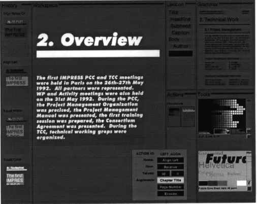
Figure 3.1. The Abatan Design Environment.
Appropriately enough, the name "Abatan" comes from a young Yuroba potter who learned her craft not by formal teaching and explicit training, but by observing, over time, how her mother and maternal grandmother applied their skills to perform their craft [Anderson 791. Abatan's method of
learning, which has grown into and is now notably referred to as the apprenticeship system, is the most common method of teaching in the fine arts and design fields today. In the spirit of Abatan and the apprenticeship system, the prototype program bearing the same name as the Yuroba potter was developed by this author to demonstrate the utilitarian functionality and advantages of using this model of learning to encode design knowledge.
The Abatan system is composed of several different components, most of which are interconnected and directly accessible to the designer (figure 3.1, 3.2). These components and their sub-components include:
A Design Environment: A Knowledge Base: A Recording Mechanism: A Graphical History: An Editor: A Learning Module: An Output Mechanism: SYSTEM CAPABILITIES AND COMPONENTS Knowledge Base
i-I
I rp 0 "' ia H srFigure 3.2. Schematic diagram of the Abatan system. Dark gray arrows suggest future extensions.
in which to construct the example layouts. The environment contains a variety of tools such as a color and font palette. containing pre-defined grammars which describe rules used to format existing categories of page-layouts, a lexicon describing the vocabulary of graphical objects available to the designer (and which the grammar affects) to construct the example layouts with, and an internal listing which describes the hierarchical structure of the graphical objects.
which translates graphical actions, verbatim, into computer code. The Recorder contains a Generator Test module that tests which actions are legitimate enough to record. which visually represents user actions that the system has
recorded.
to edit the data contained in the recordings and the history. which generalizes the recorded actions.
which both incorporates the generalized knowledge back into the system and also outputs symbolic computer code.
In order for design knowledge to be encoded into the system there are essentially four steps the designer must go through. First, a subject matter to be demonstrated must be decided upon. Second, an example layout which embodies the lower order rules that describe the idea must be built. While creating the example layout, all objects which serve as pre-conditions for the rules to operate on must be specified and all post-condition
relationships necessary for the rules to hold must be made visible. Any ambiguities which arise as a result of under specification of the rules and any aspects which are not explicit must also be clarified. In the third step, called the "learning phase," the system takes over. At this point the actions performed and recorded during the design process are analyzed and then generalized to produce a high-level, adaptable formatting procedure which describes the rules. The final stage involves having the designer test the validity of the knowledge by reapplying it to new data.
The above steps are defined and loosely based on the notion of felicity conditions which state the interaction rules a human teacher must use to effectively illustrate an idea to a student. These rules are: 1. Show all steps of the procedure; 2. Do all steps correctly; 3. Make all invisible objects and relationships visible; and 4. Introduce, at most, one new branch per lesson.
In the Abatan system, when the designer (who play the role of the teacher) is instructing the computer (the student), it is not necessary to follow these steps exactly.
SELECTING AN EXAMPLE
Initially, the designer must decide upon a subject matter to be encoded. The content of the design can range from newspaper and article layouts to technical document design. Whatever type of layout it is, the example which is to be used must fully exemplify the rules which describe the
knowledge to be encoded. In the "Title" example in chapter one, the idea was to emphasize a text string by placing a rulebar of the same color and
width underneath it, drawing more attention to the text than if it had been placed on the page by itself. If the designer wishes to encode information about how to emphasize a piece of text, by altering its typeface, point size, and color, creating a layout which only contains images and other graphic elements such as rulebars would prove useless.
BUILDING AND DESCRIBING THE EXAMPLE
In this second phase, the designer must build and describe a layout which exemplifies the idea and the rules. In order to do so, the vocabulary of graphical objects which the rules operate on (the lexicon) and the various
relationships among them (the grammar), must be made visually apparent, the logical structure of the information firmly stated, and all ambiguous
relationships clarified.
Figure 3.3. The color and font palettes.
The Design Environment (i.e., the graphical user interface) is where the designer creates the layout. Tools which accompany the environment include a color and font palette (figure 3.3). Color and transparency, and typeface and point size attributes of an object are altered using the color and font palettes respectively. As was seen in the "Title" example, spatial and dimensional attributes are manipulated directly by moving and resizing an object.
T e T itle iTit
CHeadline Headline Ieain
Subhead
I Cap ion
Bodv-,
Author Author Ato
Objects are placed into the layout area, called the Workspace, with the help of the Lexicon palette and the Exemplar Layout. The Lexicon palette, shown in figure 3.4, lists the vocabulary of lexical objects available to the designer to build the layout with. Rather than supplying generic "text" and "graphical" objects, such as those found in traditional paint programs like MacDrawTM and CanvasTM, vocabularies of objects with distinct functional purposes and attributes are defined. These include various types of headlines, titles, captions, etc. Each object's function and attributes are dependent on and inherit from one of several pre-defined grammars which describe different types of page-layouts.
2.1 P ject lanaqmenMajority Leader s Powver
Figure 3.5. The Exemplar Layout.
The Exemplar Layout (figure 3.5) illustrates examples of such grammars for laying out a page of a technical document, a Scientific American article, and a newspaper respectively. Its primary use is to visually display the affects of applying the grammar to a layout, and to show the designer what the different attributes associated with each type of object are. The Exemplar Layout is composed of objects found in the Lexicon palette (i.e., headlines, titles, rulebars), but each individual piece has been formatted with specific rules and has distinct properties and behaviors associated with it. When the designer clicks on the "Headline" button in the Lexicon palette, three corresponding headline objects are highlighted in the Exemplar Layout. One headline has the properties that its typeface is Helvetica and its point
size is 24; the other two have the typeface Times-Roman and the point size 18. The designer uses the Lexicon palette to select a general category of objects, from which the system highlights all of the available, specific instances in the Exemplar Layout. When the designer selects one of the specific headlines, its attributes are sent back into the selected Lexicon palette object to show the designer a visual example of how such an object will look when placed into the layout. To add an object to the current layout, the designer clicks on an object in the Exemplar Layout and drags it over into the Workspace. The new object's appearance and functionality reflects that found in the Layout. For example, when the text object used in the "Title" example was created, it was done so by clicking on the "Title" button in the Lexicon palette. The system then highlighted all available title objects in the Exemplar Layout offering the designer several different choices, of which one was chosen. When the title object was placed into the design, its color, typeface, point size, and dimensions reflected that found in the grammar object from which it was spawned.
The initial purpose for the Exemplar Layout and Lexicon palette is to provide the designer with an existing set of tools to create the layout with. As will be seen later, the Exemplar Layout's grammar not only sets an object's default values when it is placed into the Workspace, but uses the properties associated with the object to distinguish it from others. In addition, the system uses the grammar to perform special tests to see if an action performed on an object is legitimate given the rules which describe it.
As was also seen in the "Title" example, relationships between objects in a layout are described by physically manipulating their attributes until they conform into a final state which satisfies the post-condition rules for the design knowledge to hold. In order to fully describe a layout, all superior and subordinate relationships must be specified. If a caption's position is dependent on an image's which is dependent on a headline's, the designer must show the system each of these individual relationships before a full description of the layout can be obtained.
ENCODING THE KNOWLEDGE
The actual process of encoding the design knowledge is not a one step activity, but rather a three tier development. First, the actions performed while building the layout must be recorded. Second, the designer must be able to view and edit the recordings. Finally, the system must generalize the information. It is the job of the Recording Mechanism to capture, verbatim, the actions performed. The Graphical History visually presents the
recordings to provide feedback to the designer, allowing them to browse over what the system has recorded. The Generalization Editor enables the designer to access and edit the recordings, and the Learning Module generalizes the finalized data to produce a high level procedural description of the entire design process.
The Recording Mechanism works in conjunction with the grammar. Each time an action is performed on an object, the grammar rules associated with that object tell the Recording Mechanism whether or not it was legitimate enough to record. For example, a grammar rule describing a headline object may state that the headline's point size can not be changed to a value smaller than a subheadline's. If the designer tries to do so, the system would deduce that the action was invalid and therefore would not record it. Given the rules which describe the text and rulebar objects from the previous example, only four actions were recorded, all of which were valid. The purpose for these tests, called Generator Tests, is two part. First, to filter which actions are recorded by the system, and second, to limit initially the type of knowledge encoded. It was the choice of this author to restrict early on what could be taught to the system in hope that it would learn within a small scope. Later on as more examples were presented, the range would broaden building off of what had already been learned. The idea behind these tests came from [Kirsch 721.
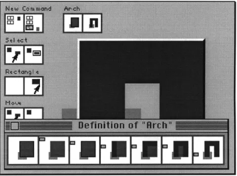
![Figure 2.6. Kurlander's Chimera records actions over time and allows users to access this information in an editable graphical history (Reprinted from [Cypher 93]).](https://thumb-eu.123doks.com/thumbv2/123doknet/14199314.479662/30.918.211.766.798.919/figure-kurlander-chimera-records-information-editable-graphical-reprinted.webp)