Publisher’s version / Version de l'éditeur:
Vous avez des questions? Nous pouvons vous aider. Pour communiquer directement avec un auteur, consultez la première page de la revue dans laquelle son article a été publié afin de trouver ses coordonnées. Si vous n’arrivez pas à les repérer, communiquez avec nous à PublicationsArchive-ArchivesPublications@nrc-cnrc.gc.ca.
Questions? Contact the NRC Publications Archive team at
PublicationsArchive-ArchivesPublications@nrc-cnrc.gc.ca. If you wish to email the authors directly, please see the first page of the publication for their contact information.
https://publications-cnrc.canada.ca/fra/droits
L’accès à ce site Web et l’utilisation de son contenu sont assujettis aux conditions présentées dans le site LISEZ CES CONDITIONS ATTENTIVEMENT AVANT D’UTILISER CE SITE WEB.
Internal Report (National Research Council of Canada. Institute for Research in Construction), 1996-09-01
READ THESE TERMS AND CONDITIONS CAREFULLY BEFORE USING THIS WEBSITE. https://nrc-publications.canada.ca/eng/copyright
NRC Publications Archive Record / Notice des Archives des publications du CNRC :
https://nrc-publications.canada.ca/eng/view/object/?id=3ba8df30-ace8-49bd-96f3-1eca47f4d8ce https://publications-cnrc.canada.ca/fra/voir/objet/?id=3ba8df30-ace8-49bd-96f3-1eca47f4d8ce
NRC Publications Archive
Archives des publications du CNRC
For the publisher’s version, please access the DOI link below./ Pour consulter la version de l’éditeur, utilisez le lien DOI ci-dessous.
https://doi.org/10.4224/20338088
Access and use of this website and the material on it are subject to the Terms and Conditions set forth at
Factors Affecting the Fire Resistance of Square Hollow Steel Columns Filled with Steel-Fibre Reinforced Concrete
- - Ser TH1 R427 no. 590 c . 2 BLDG
National Research Conseil national
I*I
Council Canada de recherches CanadaFactors Affecting the Fire
Resistance of Square Hollow
Steel Columns Filled with Steel-
Fibre Reinforced C o n c ~ t e
n a l r e p o r t ( I n s t i t u t e f
ALYSE
by V.K.R. Kodur
Internal Report No. 590
Date of Issue: September 1996
CISTI/ICIST NRC/CNRC I R C S e r
R e c e i v e d on: 10-22-96
FACTORS AFFECTING THE FIRE RESIST.4NCE OF SQUARE HOLLOW STEEL COLUMNS FILLED WITH STEEL-FIBRE REINFORCED CONCRETE
V.K.R. Kodur
ABSTRACT
Experimental and theoretical studies have been canied out to predict the fire resistance of hollow steel sections filled with various concrete types. This report deals with parametric studies on square steel columns filled with steel-fibre reinforced concrete. Using a computer program, the influence of the various study variables on the fire
resistance of these columns, namely, column section size, steel wall thickness, load,
effective length of the column, concrete strength and type of aggregate, were investigated. The results are described and the influence of the various study variables is discussed.
FACTORS AFFECTING THE FIRE RESISTANCE OF SQUARE HOLLOW STEEL COLUMNS FILLED WITH STEEL-FIBRE REINFORCED CONCRETE
by
V.K.R. Kodur
INTRODUCTION
For a number of years, the National Fire Laboratory of the Institute for Research in Construction, National Research Council of Canada (NRC), has been engaged in studies aimed at developing methods for predicting the fire resistance of concrete-filled steel columns. Both experimental and numerical studies on the fire resistance of hollow steel columns filled with concrete were canied out with the support of the Canadian Steel Construction Council (CSCC) and the American Iron and Steei Institute (AISI).
Mathematical models were developed for the calculation of the fire resistance of hollow structural steel (HSS) sections filled with concrete. Columns of various sizes and shapes were studied and a large number of tests, for the validation of the models, were carried out. Among the various parameters investigated were three types of concrete filling: plain concrete, bar-reinforced concrete and SIC-1-fibre reinforced concrete (SFRC)
Research on the fire resistance of HSS columns filled with plain [I] and with bar- reinforced concrete [2] was previously completed.
At present, the research on SFRC-filled HSS columns has reached a stage at which sufficient data, suitable for release, has been produced. This report contains the data showing the influence of the important factors on the fire resistance of square steel
columns filled with SFRC. The data, generated by a mathematical model [3] programmed for computer processing, will enable the assessment of the fire resistance of the columns as a function of the variables that determine it.
The model was developed at BRC with the support of the Canadian Steel Construction Council and the American Iron and Steel Institute.
2 STUDY VARIABLES
The study variables that were considered in this project are given below,
2.1 Column Size
All square columns, listed in the CISC Handbook of Steel Construction [4], whose outside dimensions were equal to or greater than 101.6 mm were considered. The column with an outside dimension of 101.6 mm was regarded as the smallest column suitable for concrete filling. The seven column sizes selected for the parametic study are given in Tables 1-18.
2.2 Thickness of the Steel Wall
To assess thc effect of the stccl wall thickness on the fire resistance of the columns, thc cxrrcrne valucs of wall thickness listed in the CISC Handbook of Steel Construction [ 4 for each column size equal to or greater than 101.6 mm were used. The selected wall thicknesses are given in Tables 1-18.
2.3 Load
The influence of the load on the fire resistance of the column was evaluated by calculating the strength of the column, i.e., the maximum load that the column can
support, as a function of time during the exposure to fire. By definition, the fire resistance of the column is equal to the time during which the column can support a specific load. Thus, fire resistance can be determined, for any load using the strength versus time relations. In this study, the strength of the column was calculated every 10 min during exposure to fire.
2.4 Effective Length
To study the influence of the effective length on fire resistance, calculations of the strength of the column, during exposure to fire, were made for column effective lengths of 2.5,3.0 and 4.5 m.
2.5 Concrete Strength
The influence of the strength of the concrete filling on the fire resistance of the column was studied by determining the fire resistance of columns with concrete compressive strengths of 20,35 and 55 MPa.
2.6 Type of Aggregate
The influence of the type of aggregate on fire resistance was evaluated by using the relevant material properties of concrete included in the mathematical model. Two
concrete types, siliceous and carbonate aggregate concrete, were considered in the parametric study. The material properties are given in Appendix A.
3 CALCULATION MiTHOD
The calculation of the fire resistance of the columns was carried out according to the method described in Reference 3. The calculation of fire resistance consists of three steps:
1. Calculation of the fire temperature.
2. Calculation of the temperatures in the column.
3. Calculation of the strength of the column during exposure to fire, including an analysis of the stress and strain distriiution.
A flow chart of the calculation procedure is shown in Figure 1.
3.1 F i e Temperature
It is assumed that the entire surface area of the column is exposed to the heat of a fire, whose temperature course follows that of the standard fire described in ASTM E l 19
[5]
or CAN4-S101 [6]. This temperature course can be approximated by the following expression:3.2 Temperatures of Column During Fire Exposure
The column temperatures are calculated by a finite difference method. Because the finite difference heat transfer equations for the column are given in detail in Reference 3, only a brief description of the method is given in this report.
The cross-sectional area of the column is subdivided into a number of elements, arranged in a triangular network. The temperature rise in an element can be derived by creating a heat balance for the element. By solving the heat balance equations, the temperature history of the column can be calculated, using the temperature-dependent thermal properties of the concrete and steel of which the column is composed. These properties are given in Appendix A.
The effect of moisture in the concrete on the column temperature is taken into account by assuming that, in each layer, the moisture starts to evaporate when the
temperature reaches 100°C. In the period of evaporation, all the heat supplied to a layer is used for evaporation until the layer is dry.
3.3 Strength of Column During Fire Exposure
In order to calculate the strains and stresses in the column and its strength, the cross-sectional area of the column is divided into a number of square elements. The temperatures, stresses and strains at the centre of each element are assumed to be representative of those of the entire element.
The strain in an element of steel is given by the sum of the thermal expansion of the steel, the axial strain of the column due to compression and the strain due to bending of the column. A similar calculation is performed for the concrete elements.
To simplify the strength calculations, the following assumptions are made: 1. The curvature of the column varies from pin-ends to mid-height according to a
straight line relation.
2. Concrete has no tensile strength.
3. There is no slip between steel and concrete.
4. There is no composite action between the steel and concrete.
With these assumptions, and the aid of the stress-strain relations given in Appendix
A, the stresses at mid-section in the steel and concrete can be calculated for any value of axial strain and curvature. From these stresses, the load that each element carries and its contribution to the internal moment at mid-section can be derived. By adding the loads and moments, the load that the column carries and the internal moment at mid-section can be calculated.
The strength of the column, during exposure to fire, can be determined by successive iterations of the axial strain and curvature until the internal moment at mid- section is in equilibrium with the applied moment.
The fire resistance of the column is derived by calculating the strength of the column as a function of the time of exposure to fire. This strength reduces gradually with time and, at a certain point, the strength becomes so low that it is no longer sufficient to support the load. At this point, the column becomes unstable and is assumed to have failed. The time to reach this failure point is the fire resistance of the column.
4 RESULTS AM) DISCUSSION
Using the mathematical model described in Reference 3, and the material
properties given in Appendix A, the strength of the columns during exposure to fire was calculated for the values of the study variables discussed in Section 2. The results are given in Tables 1- 18.
The influence of the various study variables can be assessed by comparing the fire resistances calculated for the respective study variables, with that of a reference column. For this purpose, a column with an outside dimension of 254.0 mm, a steel wall thickness of 6.35 mm, an effective length of 2.5 m and siliceous concrete filling with a strength of 35 MPa was selected as the reference column. Two reference loads were selected for the fire resistance comparisons, namely 270 kN and 1300 kN.
The influence of the various study variables are shown in Figures 2-7 and will be discussed below.
4.1 Column Size
In Figure 2, the fire resistance of the SFRC-filled HSS columns is shown as a function of the steel outside dimension for the two selected reference loads of 270 kN and
1300 kN. The curves in this figure and the values in Table 2 for siliceous aggregate concrete filling and in Table 1 1 for carbonate aggregate concrete filling, indicate that the column outside dimension, which is a measure of the column section size, has a
pronounced influence on the fire resistance of the column. The curves in Figure 2 indicate that the fire resistance increases approximately quadratically with the column outside dimension.
4.2 Thickness of the Steel Wall
The influence of the thickness of the steel wall on the fire resistance of the SFRC- filled HSS columns is shown in Figure 3. It can be seen that, for column sizes of
203.2 mm and smaller, the fire resistance tends to increase and, for column sizes
254.0 mm and larger, to decrease with increasing wall thickness. The influence of the wall thickness is small, however, in comparison to that of the column size. For practical
purposes, it seems warranted to neglect the influence of thickness of the steel wall on the fire resistance of the column.
4.3 Load
In Figure 4, the fire resistance of three SFRC-filled HSS columns having outside dimensions of 101.6 rnm, 152.4 mm and 304.8 rnm are shown as a function of the load. For fire resistances greater than 45 min, which lie in the practical region, the f ~ e resistance of the columns increases steeply with decreasing load. The influence of load on fire
resistance is relatively higher for the larger columns. For the column with an outside dimension of 304.8 mm, for example, a reduction in load of about 52% from 3600 kN to
1745 kN, will double the fire resistance of the column from approximately 50 min to 100 min. For the intermediate-sized column, which has an outside dimension of 152.4 mm, the load has to be reduced by about 87% to double the fire resistance from 50 min to 100 rnin.
4.4 Effective Length
In Figure 5, the fire resistance of the columns is shown as a function of the
effective length of the column for the two selected reference loads of 270 kN and 1300 kN and two strengths of the concrete filling, namely, 20 MPa and 35 MPa. The curves show that, in the range of effective lengths of 2.5-4.5
m
the fire resistance is approximately inversely proportional to the effective length.The influence of the effective length is somewhat greater for low loads than for high loads. The influence of the compressive strength, however, is relatively greater for the higher loads. It can be seen in Figure 5 that, for low loads and higher values of effective length, the influence of the compressive strength on the fire resistance of the column becomes very small.
4.5 Concrete Strength
The influence of the concrete strength on the fire resistance of the columns is shown in Figure 6 for the two selected reference loads of 270 kN and 1300 kN. The curves indicate a moderate influence of concrete strength on the fire resistance of the column.
The influence of the compressive strength is greater for the higher loads than for the lower loads. For the lower loads, the fire resistance of the column increases by approximately 40% if the concrete strength is roughly tripled and for the higher load by about 100%.
4.6 Type of Aggregate
In Figure 7, the fire resistance of two columns, with outside dimensions of
177.8 mm and 304.8 mm, is shown as a function of the load, for a siliceous aggregate and a carbonate aggregate concrete filling. The curves show that, for smaller column sizes, the aggregate type has very little influence on the fire resistance of the column. For larger column sizes, the fire resistances of the columns filled with steel fibre-reinforced (SFR) carbonate aggregate concrete are higher
than
that of a column filled with SFR siliceous aggregate concrete. In the practical region, namely, for fire resistances above 45 min, the difference in fire resistance between carbonate aggregate and siliceous aggregate concrete filling varies &om approximately 10 to 50%. The difference in fire resistance tends to increase with lower loads or higher fire resistances. This tendency is also shown by the tabulated values in Tables 1-18 for other column section sizes, steel wail thicknesses, column effective lengths and concrete strengths.4.7 Discussion
A comparison of results from parametric studies in Tables 1-1 8 with that in Reference 7 indicate that the strength of SFRC-filled HSS columns is only slightly higher
than
those for columns filled with plain concrete. However, the main benefit in filling HSS columns with SFRC is that predictable fire resistances can be obtained up to 3 h even under full design load levels. The small increase in strength is mainly due to the assumption in the model that the SFRC has no tensile strength. While this is a valid assumption for plain concrete filling, it leads to conservative results for SFRC filling since its tensile strength is higher than that of plain concrete. However, this could not be accounted for in the model as there is no information on stress-strain curves of SFRC at elevated temperatures.Data from the tests indicate that fire resistances up to 3 h can be obtained for square HSS columns filled with steel-fibre reinforced concrete. In contrast. the fire resistance of HSS columns filled with plain concrete is limited to 1-2 h [8].
The increased fire resistance of SFRC filled columns, as compared to plain concrete-filled columns [9], can be attributed to the superior mechanical properties of fibre-reinforced concrete. Results from the experimental studies carried out to determine mechanical properties at elevated temperatures [lo] indicate that the compressive strength of fibre-reinforced concrete increases with temperature up to about 400°C. The steel fibres prevented early cracking and also contributed to the compressive strength of concrete at elevated temperatures.
4.8 Limitations
Comparisons of calculated f r e resistances with test results [3, 111 show that calculated fire resistances are,
id
general, lower or close to those measured, provided limitations are set with regard to load, fue resistance time and concrete strength.However, there are instances in which the measured fire resistance is lower than
that calculated. When the load is too high or the test duration very long, the column failure time is no longer reproducible and the fire resistance becomes unpredictable. This is also the case for columns with high strength concrete filling.
A possible reason for the unpredictable failure is the creation, during fire exposure, of local stresses and cracks. In the case of high strength concrete filling, increased
brittleness of the concrete may also be a contributing factor.
If limits are set with regard to the load, fire resistance time and concrete strength, the fire resistance of the columns is predictable and the information given in this report can be used for the evaluation of the f ~ e resistance of square HSS columns filled with steel fibre-reinforced concrete. Until further studies, which are now in progress at
LRC,
are completed, it is recommended that the following limitations not be exceeded in the use of the information in this report:(a) Loads are not greater than the factored resistance of the concrete core determined in accordance with CANICSA-S16.1-M89 [12].
@) Fire resistance not greater that 3 h.
(c) Specified compressive strength of concrete at 28 days not greater than 55 MPa. With these limitations, predicted fire resistances are, in general, not more than approximately 30% lower
than
those measured and, in a few cases, not more than 10% higher.The fire resistances for other conditions or configurations than that given in Tables 1-18 or in Figures 2-7, can be derived by linear interpolation between tabulated or plotted values.
5 SUMMARY
In summary, it was found that, of the various variables studied, the column section size and the load on the column have the greatest influence on the fire resistance of the column. The effective length of the column, concrete strength, and type of aggregate have a moderate influence on the fire resistance of the column. The influence of the steel wall thickness is insignificant.
6. REFERENCES
1. Lie, T.T., and Stringer, D.C., Calculation of Fire Resistance of Steel Hollow
Structural Steel Columns Filled with Plain Concrete, Can. J. Civ. Engrg., 21(3), 1994, pp. 382-385.
2. Lie, T.T., and Kodur, V.K.R., Fire Resistance of Steel Columns Filled with Bar- Reinforced Concrete, Journal of Structural Engineering, 122 (I), January, 1996. 3. Kodur, V.K.R. and Lie, T.T., Evaluation of the Fire Resistance of Rectangular Steel
Columns Filled with Fibre-Reinforced Concrete, Canadian Journal of Civil Engineering, (in press).
4. Handbook of Steel Construction, Canadian Institute of Steel Construction.
Willowdale, Ontario, 199 1.
5. Standard Methods of Fire Tests of Building Construction and Materials, ASTM
E l 19-88, American Society for Testing and Materials, Philadelphia, PA, 1988. 6. Standard Methods of Fire Endurance Tests of Building Construction and Materials,
CAN4-S 10 1 -M89, Underwriters' Laboratories of Canada, Scarborough, Ontario, 1989.
7. Lie, T.T., Irwin R.J., and Chabot, M., Factors Affecting the Fire Resistance of Square Hollow Steel Columns Filled with Plain Concrete, IRC Internal Report No. 633.
1992.
8. Lie, T.T and Chabot, M., A Method to Predict the Fire Resistance of Circular
Concrete Filled Hollow Steel Columns, Journal of Fire Protection Engineering, 2(4), 1990, pp. 11 1-126.
9. Lie, T.T. and Chabot, M., Experimental Studies on the Fire Resistance of Hollow Steel Columns Filled with Plain Concrete, IRC Internal Report No. 6 1 1, National Research Council of Canada, Institute for Research in Construction, Ottawa, Ontario, 1992.
10. Lie, T.T. and Kodur, V.K.R, Mechanical Properties of Fibre-Reinforced Concrete at Elevated Temveratures. IRC Internal Re~ort No. 687. National Research Council of Canada, 1 n s t i k for ~ e s e a r c h in ~ons&tion, Ottawa, Ontario, 1995.
11. Kodur, V.K.R., and Lie, T.T., Experimental Studies on the Fire Resistance of Square Hollow Steel Columns Filled with Steel Fibre-Reinforced Concrete, IRC Internal Report No. 662, Institute for Research in Construction, National Research Council of Canada, Ottawa, 1996.
12. Limit States Design of Steel Structures, CANICSA-S16.1-M89, Canadian Standards Association, Rexdale, Ontario, 1989.
INDEX
OF
TABLES Table 1 Table 2 Table 3 Table 4 Table 5 Table 6 Table 7 Table 8 Table 9Strength (kN) of SFRC-Wed HSS Column as a Function of 'lime for Various Square Column Sizes and Steel Wall Thicknesses
(Effective Length: 2.5 m, Concrete Strength: 20 MPa, Aggregate: Siliceous) Strength (kN) of SFRC-Fied HSS Column as a Function of Time
for Various Square Column Sizes and Steel Wall Thicknesses
(Effective Length: 2.5 m, Concrete Strength: 35 MPa, Aggregate: Siliceous) Strength 0 of SFRC-Filled HSS Column as a Function of 'lime
for Various Square Column Sizes and Steel Wall Thicknesses
(Effective Length: 2.5 m, Concrete Strength: 55 MPa, Aggregate: Siliceous) Strength
(W
of SFRC-Filled HSS Column as a Function of T ~ m e for Various Square Column Sizes and Steel Wall Thicknesses(Effective Length: 3.0~1, Concrete Strength: 20 MPa, Aggregate: Siliceous) Strength (kN) of SFRC-Fied HSS Column as a Function of Time
for Various Square Column Sizes and Steel Wall Thicknesses
(Effective Length: 3.0m, Concrete Strength: 35 MPa, Aggregate: S i m ) Strength (kN) of SFRC-Fiied HSS Column as a Function of =me
for Various Square Column Sizes and Steel Wall Thicknesses
(Effective Length: 3.0m. Concrete Strength: 55 MPa, Aggregate: Siliceous) Strength 0 of SFRC-Fied HSS Column as a Function of Time
for Various Square Column Sizes and Steel Wall Thicknesses
(Effective Length: 4.5m, Concrete Strength: 20 MPa, Aggregate: Siliceous) Strength 0 of SFRC-Filled HSS Column as a Function of Time
for Various Square Column Sizes and Steel Wall Thicknesses
(Effective Length: 4.5m. Concrete Strength: 35 MPa, Aggregate: Siliceous) Strength 0 of SFRC-Filled HSS Column as a Function of Tlme
for Various Square Column Sizes and Steel Wall Thicknesses
Table 10 Table 11 Table 12 Table 13 Table 14 Table 15 Table 16 Table 17 Table 18
Strength (kN) of SFRC-Fied HSS Column as a Function of Time for Various Square Column Sizes and Steel Wall Thicknesses
(Effective Length: 2.5m, Concrete Strength: 20 MPa, Aggregate: Carbonate) Strength (kN) of SFRC-Fied HSS Column as a Function of lime
for Various Square Column Sizes and Steel Wall Thicknesses
(Fffective Length: 2.5m, Concrete Strength: 35 MPa, Aggregate: Carbonate) Strength (kN) of SFRC-Fied HSS Column as a Function of Time
for Various Square Column Sizes and Steel Wall Thicknesses
(Effective Length: 2 . 5 1 ~ Concrete Strength: 55 MPa, Aggregate: Carbonate) Strength (kN) of SFRC-Filled HSS Column as a Function of Time
for Various Square Column Sizes and Steel Wall Thichsses
(Effective Length: 3.0m. Concrete Strength: 20 MPa, Ag-%gate: Carbonate) Strength (kN) of SFRC-Fied HSS Column as a Function of T i e
for Various Square Column Sizes and Steel Wall Thicknesses
(Effective Length: 3.0m. Concrete Strength: 35 MPa, Aggregate: Carbonate) Strength (kN) of SFRC-Fied HSS Column as a Function of Time
for Various Square Column Sizes and Steel Wall Thicknesses
(Effective Length: 3.0m. Concrete Strength: 55 MPa, Aggregate: Carbonate) Strength (kN) of SFRC-Fied HSS Column as a Function of Time
for Various Square Column Sizes and Steel Wall Thicknesses
(Effective Length: 4.5m, Concrete Strength: 20 MPa, Aggregate: Carbonate) Strength (kN) of SFRC-Fded HSS Column as a Function of Time
for Various Square Column Sizes and Steel Wall Thicknesses
(Effective Length: 4.5m. Concrete Strength: 35 MPa, Aggregate: Carbonate) Strength (kN) of SFRC-Fded HSS Column as a Function of Time
for Various Square Column Sizes and Steel Wall Thicknesses
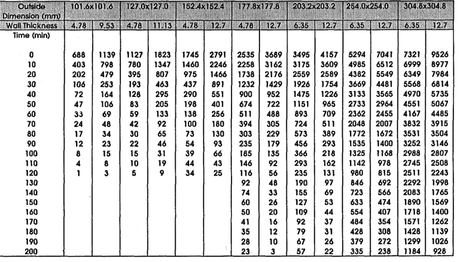
Table 1 Strength (kN) of SFRC-filled HSS Column as a function of time
(Effectlve length = 2.5 m. Concrete Strength = 20 MPa, Aggregate = Siliceous)
Time (min) 0 10 20 30 40 50 60 70 80 90 100 110 120 130 140 150 160 170 180 190 200
Note: The ' beslde certain values indicate that the data at that point is not reliable due to non convergence 631 444 237 121 74 46 33 22 15 9 6 2 0 1088 836 504 266 164 92 58 39 26 17 10 5 0 836 613 332 171 107 67 49 38 26 17 10 5 1 1623 1295 832 475 291 183 111 78 51 34 21 10 2 1196 931 562 318 202 127 86 61 46 36 29 16 7 2407 1987 1348 839 514 353 213 143 103 76 48 27 10 1611 1333 855 527 361 245 167 118 86 60 43 32 22 12 9 7 2 1 0 0 0 3053 2618 1840 1199 730 556 338 236 158 116 84 63 32 7 1 1 0 0 0 0 0 2330 1987 1428 880 620 448 315 234 169 121 84 55 33 18' 9' 19 18 0' 2 1 1 3752 3220 2373 1609 1068 789 538 372 267 188 131 90 54 29 16' 20 3 2 1 0 0 3324 2982 2398 1822 1398 1089 854 678 533 419 318 240 169 111 68 16' 2 1 2 1 0 0 5278 4697 3744 2772 1938 1458 1087 798 601 455 341 244 163 94 32 16' 2 1 2' 7' 9 0
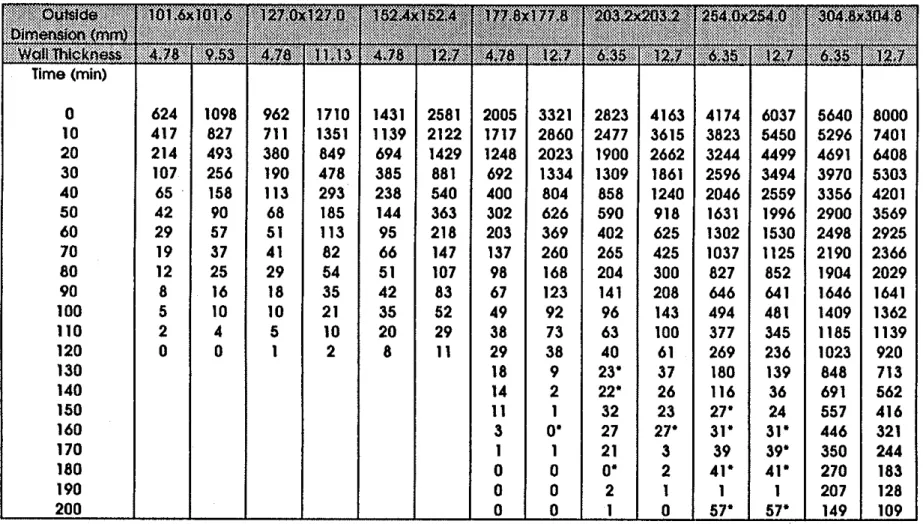
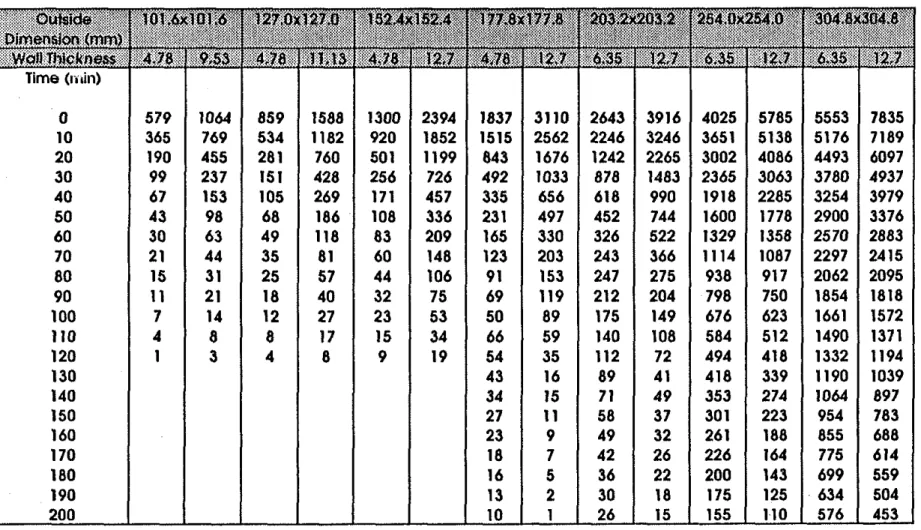
Table 2 Strength (kN) of SFRC-filled HSS Column as a function of time
(Effective length = 2.5
m.
Concrete Strength = 35 MPa, Aggregote = Siliceous). . . . . Dimewbn ,
.
, . , , , , ,,., , ~ i , . 2,7 6 3 51
12.7 Time (min) 0 624 1098 962 1710 1431 2581 2005 3321 2823 4163 4174 6037 10 417 827 711 1351 1139 2122 1717 2860 2477 3615 3823 5450 20 214 493 380 849 694 1429 1248 2023 1900 2662 3244 4499 30 107 256 190 478 385 881 692 1334 1309 1861 2596 3494 40 65 158 113 293 238 540 400 804 858 1240 2046 2559 50 42 90 68 185 144 363 302 626 590 918 1631 1996 60 29 57 51 113 95 218 203 369 402 625 1302 1530 70 19 37 41 82 66 147 137 260 265 425 1037 1125 80 12 25 29 54 51 107 98 168 204 300 827 852 90 8 16 18 35 42 83 67 123 141 208 646 641 100 5 10 10 21 35 52 49 92 96 143 494 481 110 2 4 5 10 20 29 38 73 63 100 377 345 120 0 0 1 2 8 11 29 38 40 61 269 236 130 18 9 23' 37 180 139 140 14 2 22' 26 116 36 150 11 1 32 23 27' 24 160 3 0' 27 27' 31' 31' 170 1 1 21 3 39 39' 180 0 0 0' 2 41' 41' 190 0 0 2 1 1 1 200 0 0 1 0 57' 57'Table 3 Strength (kN) of SFRC-filled HSS Column as a function of time
(Effective length = 2.5 m. Concrete Strength = 55 MPa. Aggregate = Slllceous)
Note: The
'
beside certain values indicate that the data at that point is not reliable due to non convergence Time (min) 0 10 20 30 40 50 60 70 80 90 100 110 120 130 140 150 160 170 180 190 200 697 458 222 107 66 44 3 1 19 12 8 5 2 0 1155 851 500 256 159 92 59 38 25 16 10 4 0 1136 839 446 213 122 71 55 46 32 19 1 1 5 1 1837 1429 878 486 295 188 117 8 7 56 35 21 10 2 1754 1447 870 467 278 164 103 72 56 48 42 23 10 2804 2310 1561 970 585 386 227 151 113 91 56 30 1 1 2535 2223 1699 1 1 1 1 673 433 257 158 110 74 57 46 37 26 20 15 0' 2 1 0 0 3704 3193 2298 1530 906 714 406 286 178 132 103 86 45 12 4I *
0' 2 1 0 0 3504 3134 2522 1804 1268 869 594 410 266 162 107 70 48 30 31 47 35 28 1 4' 2' 4163 3615 2662 1861 1240 918 625 425 300 208 143 100 61 37 26 23 35' 3 2 1 0 5290 4955 4370 3610 2902 2348 1900 1511 1218 954 734 557 402 275 179 35 47' 52' 54' 63' 77' 7026 6447 5513 4452 3336 2656 2042 1543 1180 878 664 480 328 199 44 37 47' 52' 54" 63' 102' 7316 6982 6387 5598 4813 4226 3681 3261 2857 2478 2137 1806 1573 1311 1077 873 700 550 425 326 235 9507 8946 7956 6849 5556 4832 4044 3329 2902 2368 1981 1674 1368 1077 860 656 504 383 287 202 129Table 5 Strength (kN) of SFRC-filled HSS Column as a function of time
(Effective length = 3.0
m.
Concrete Strength = 35 MPa, Aggregate = Siliceous)Note: The
'
beslde certain values indicate that the data at thot polnt is not reliable due to non convergence Time (min) 0 10 20 30 40 50 60 70 80 90 100 110 120 130 140 150 160 170 180 190 200 595 387 198 99 60 38 26 17 11 7 4 2 0 1078 790 464 240 147 83 53 34 23 15 9 4 0 874 597 306 152 98 60 44 35 24 15 9 4 1 1608 1235 782 437 266 166 100 71 47 30 18 9 2 1318 981 547 284 173 104 71 54 42 33 27 15 7 2400 1915 1267 761 460 315 190 127 92 69 43 24 9 1850 1504 915 519 328 207 137 94 69 50 40 30 22 15 12 9 3 1 0 0 0 3136 2622 1767 1116 653 494 287 201 134 102 76 59 30 8 2 1 0' 1 0 0 0 2639 2232 1572 922 612 412 274 194 138 96 67 47 32 18' 18' 26 22 18 4 2 1 3929 3316 2365 1575 1012 725 473 317 223 156 109 78 50 28 22 20' 22 3 2 1 0 4028 3624 2968 2288 1749 1351 1049 796 617 484 366 270 193 124 23 21 28' 30' 35' 4 45' 5791 5128 4067 2991 1936 1500 1119 680 597 442 327 228 146 73 27 22 27' 30' 35' 4 66' 5546 5152 4481 3743 3099 2628 2213 1894 1614 1364 1157 957 807 658 531 421 334 259 198 149 98 7815 7164 6070 4921 3809 3167 2543 2005 1683 1355 1102 896 716 547 422 313 238 178 132' 149 98Table 6 Strength (kN) of SFRC-filled HSS Column as a function of lime
(Effective length = 3.0
m,
Concrete Strength = 55 MPa, AQgleQate = Siliceous)Time (min) 0 10 20 30 40 50 60 70 80 90 100 110 120 130 140 150 160 170 180 190
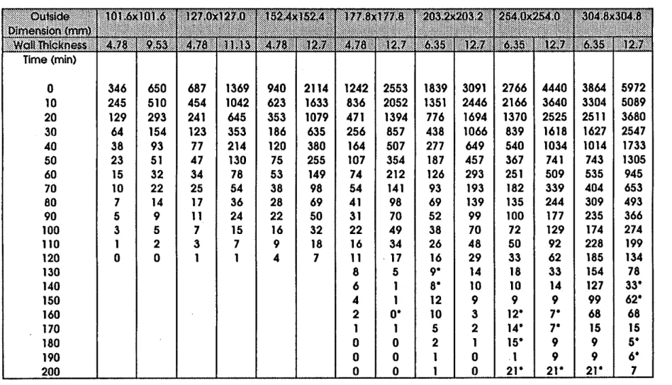
Table 7 Strength (kN) of SFRC-filled HSS Column as a function of time
(Effective length = 4.5 m, Concrete Strength = 20 MPa. Aggregate = Siliceous)
Time (min) 0 10 20 30 40 50 60 70 80 90 100 110 120 130 140 150 160 170 180 190 200
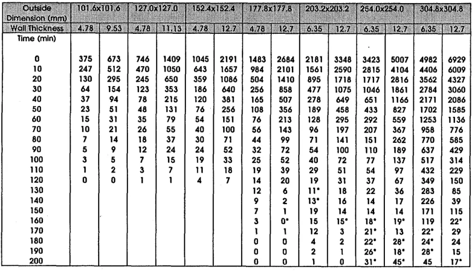
Table 8 Strength (kN) of SFRC-filled HSS Column as a function of time
(Effective length = 4.5 m. Concrete Strength = 35 MPa. Aggregate = Siliceous1
Table 9 Strength (kN) of SFRC-filled HSS Column as a function of fime
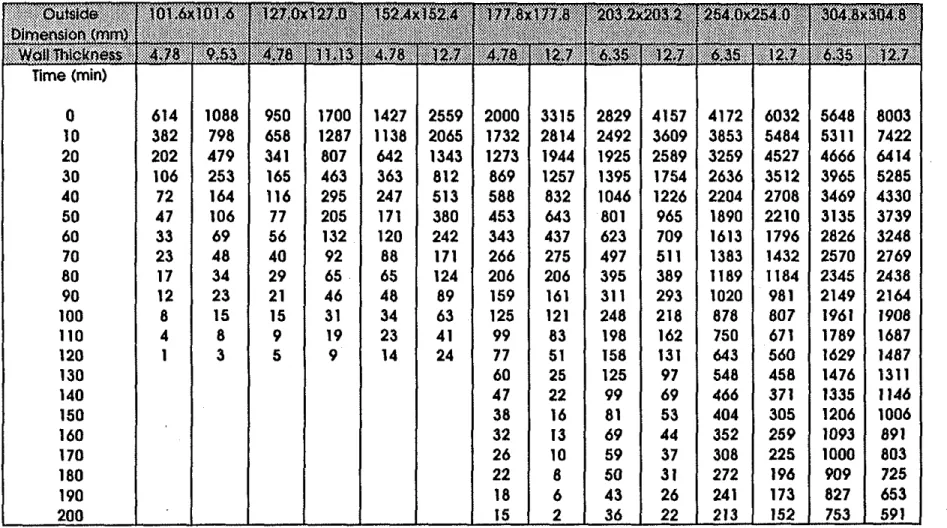
(Effective length = 4.5m .Concrete Strength = 55 MPa. Aggregate = Siilceousl
0 417 689 831 1462 1212 2293 1806 2872 2619 3691 4308 5739 6496 10 258 516 481 1080 709 1677 1190 2191 1823 2849 3675 4746 5867 20 132 297 250 655 371 1099 588 1432 1062 1798 2767 3253 4941 30 63 154 123 353 186 644 256 863 543 1093 1303 2178 3989 40 38 94 79 216 I21 383 166 507 318 649 786 1324 3180 50 23 51 49 133 78 257 109 360 192 460 511 931 2587 60 16 32 36 81 56 153 74 215 130 296 335 619 2081 70 1 1 2 1 27 56 42 102 58 147 99 199 234 403 1534 80 7 14 19 37 32 73 47 101 74 146 166 283 1241 90 5 9 12 25 27 56 35 75 58 103 118 201 1013 100 3 5 7 15 21 35 28 56 44 74 82 144 830 110 1 2 3 7 12 19 22 45 32 55 60 103 677 120 0 0 1 1 5 7 17' 23 22' 35 42 74 556 130 18 9 15' 22' 26 40 445 140 13 4 19' 24 19 22 354 150 8
I *
28 20 20' 21 274 160 4 0' 22 15 25' 26' 188 170 2 2 17 5 28' 29' 30' 180 1 1 12 3 31' 39' 32' 190 0 0 4 1 37' 47' 39- 200 0 0 2 0 43' 64' 401
I Table 10 Strength (kN) of SFRC-filled HSS Column as a function of time
(Effectlve length = 2.5 m, Concrete Strength = 20 MPa, Aggregate = Carbonate) I ." '*.""""' ', ." ?,,,,$ , ,' .:?>..?.~~.,%y,
~ ~ ~ m & g ) # $ y
,, , , .,.,, , ..., ,,, ,,, . . . 7.:::: .$cNla&iw@kg .:. ..:. ... . ..: ... : . . :.:.: .:*.: ,:.: ::.;,.-
Time (min) 0 10 20 30 40 50 60 70 80 90 100 110 120 130 140 I50 160 170 180 190 200Table 11 Strength (kN) of SFRC-filled HSS Column as a functlon of time
[Effective length = 2.5 rn, Concrete Strength = 35 MPa, Aggregate = Carbonate)
.~
. . , ,WoIIThickrle~s~
I
4.78'1
,9,53'; ,41781
1'1.13
1.4.781'
1 2 ~ 4.78 g1
,i12.7I
6-351
i2.7 6.35I
, 12.7 6.35I
:.i2.7 "Time (min)
I I I I I I I I I I I I I I I I
Table 12 Strength (kN) of SFRC-filled HSS Column as a function of time
(Effective length = 2.5
m.
Concrete Strength = 55 MPo. Aggregate = Carbonate)I
Time (rn*I I I I
I
Table 13 Strength (kN) of SFRC-filled HSS Column as a functlon of time
(Effective length = 3.0 m, Concrete Strength = 20 MPa, Aggregate = Carbonate]
Table 14 Strength (kN) of SFRC-filled HSS Column as a funclion of lime
(Effecthe length = 3.0 m, Concrete Strength = 35 MPa. Aggregate = Carbonate)
Time (txiin) 0 10 20 30 40 50 60 70 80 90 100 110 120 130 140 150 160 170 180 190 200
Table 15 Strength (kN) of SFRC-filled HSS Column as a function of time
(Effective length = 3.0 m, Concrete Strength = 55 MPa, Aggregate = Carbonate)
Time (min) 0 621 1101 1001 1675 1578 2575 2318 3425 3269 4400 5121 6750 10 365 769 619 1187 1218 1968 1985 2831 2865 3723 4758 6112 20 190 455 281 760 592 1213 1437 1844 2206 2576 4073 5064 30 99 237 151 428 293 726 910 1144 1577 1705 3313 3952 40 67 153 105 269 191 457 540 715 1131 1138 2748 3042 50 43 98 68 186 130 336 402 538 833 842 2327 2461 60 30 63 49 118 91 209 310 353 645 589 1963 1980 70 22 44 35 81 65 149 247 216 511 410 1649 1580 80 15 31 26 57 48 106 199 162 414 308 1402 1288 90 11 21 18 40 34 75 157 126 331 228 1195 1092 100 7 14 13 27 25 53 127 94 260 167 1023 896 110 4 8 8 17 16 35 103 63 211 121 880 747 120 1 3 4 8 10 19 81 37 169 81 756 621 130 65 17' 137 99 644 509 140 52 23 110 74 550 419 150 43 18 92 59 470 348 160 36 14 77 50 410 296 170 29 11 66 41 356 257 180 25 8 56 34 314 225 190 20 3 48 28 275 196 200 16 2 40 23 244 173
Table 16 Strength (kN) of SFRC-filled HSS Column as a funcflon of time
(Effective iength = 4.5
m,
Concrete Strength = 20 MPa, Aggreg~te = Carbonate)Time (min) 0 340 626 681 1376 915 2093 1220 2527 1821 3084 2749 4429 10 238 492 440 1032 600 1608 773 2007 1272 2366 2103 3576 20 123 291 232 634 337 1057 449 1368 734 1646 1297 2421 30 64 152 123 347 183 622 248 828 420 1027 776 1527 40 43 98 84 217 125 382 170 514 280 641 518 968 50 28 63 55 148 86 276 117 387 203 474 379 722 60 19 39 39 94 61 170 84 250 142 321 321 523 70 14 28 28 65 44 118 62 148 105 218 218 361 80 10 20 20 46 32 83 46 108 78 161 161 161 90 7 13 14 33 23 59 34 83 58 117 117 117 100 4 9 10 22 16 41 24 61 43 83 83 83 110 2 5 6 13 11 26 17 41 30 58 58 58 120 1 2 3 6 6 15 10 24 19 37 37 37 130 5 10 10' 19 106 106 140 1 1 3' 6 95 95 150 6' 1 15 9 8 1 58 100 0 0 12 7 70 49 170 0 0 10 6 6 1 44 180 0 0 9 0 53 38 190 0 0 7 0 47 33 200 0 0 6 0 4 1 29
Table 17 Strength (kN) of SFRC-filled HSS Column as a function of time
(Effectlve length = 4.5 rn, Concrete Strength = 35 MPa. Aggregate = Carbonate)
Time (min) 0 345 649 732 1413 1017 2154 1447 2645 2152 3310 3406 4976 10 238 492 440 1032 600 1608 903 2011 1459 2472 2832 3839 20 123 291 232 634 337 1057 449 1368 734 1646 1595 2685 30 64 152 123 347 183 622 248 828 420 1027 949 1734 40 43 98 84 217 125 382 170 514 280 641 618 1100 50 28 63 55 148 86 276 117 387 203 474 444 807 60 19 39 39 94 61 170 84 250 142 323 317 577 70 14 28 28 65 45 118 62 148 105 218 234 234 80 10 20 2 1 46 33 84 46 108 78 162 177 177 90 7 13 14 39 24 59 34 83 59 117 135 135 100 4 9 10 22 17 41 24 62 43 83 255 255 110 2 5 6 13 11 26 17 41 30 58 242 242 120 1 2 3 6 6 15 10 24 19' 37 221 221 130 5 10 10' 20 191 191 140 2 1 28 6' 167 114 150 11' 1 26 16 142 102 160 1 1 22 13 123 86 170 0' 0 18 10 106 76 180 1 0 15 1 93 66 190 0 0 13 1 82 58 200 0 0 11 1 72 50 ?
Table 18 Slrengfh (kN) of SFRC-filled HSS Column as a function of time
(Effective length = 4.5 rn, Concrete Strength = 55 MPa, Aggregate = Carbonate)
50 28 63 55 148 86 276 117 387 203 474 1010 899 60 19 39 39 94 61 170 84 250 143 323 862 637' 70 14 28 28 65 45 118 62 148 105 218 719 719 80 10 20 2 1 46 33 84 46 108 79 162 616 616 90 7 13 14 33 24 59 34 83 59 117 531 531 100 4 9 10 22 17 41 25 62 43' 84 463 463 110 2 5 6 13 11 26 17 41 30' 59 401 401 120 1 2 3 6 6 15 10 24 19' 37 354 354 130 5 10 10' 20' 304 196 140 2 2 46 6' 260 188 150 17' 2 4 1 25 222 161 160 1 1 34 21 193 136 170 1 1 28 16 166 120 180 1 0 24 1 147 104 190 1 0 20 1 129 92 200 0 0 17 1 112 79
INDEX
OF
FIGURESFigure 1 Fiow chart of calculation procedure
Figure 2
Fi
resistances as a function of square columnsizes
for loads of 270 kN and 1300 kNFigure 3
Ei
resistance as a function ofwall
thickness for various square steel columnsFigure 4
F i
resistance as a function of load for various square column sizesFigure 5
Fi
resistanceas
a function of effective length of a square column for loads of 270 kN and 1300 kN, and concrete strengths of 20 MPa and 35 MPa Figure 6 F i e resistance of square columns as a function of concrete strength forloads of 270kN and 1300 kN
Figure 7 Fire resistance as a function of load for siliceous and carbonate aggregate concrete for two square column sizes
FIRE TEMPERATURE
CALCULATION OF
MEMBER TEMPERATURES
INITIAL CURVATURE AND AXIALSTRAIN
STRAINS AND STRESSES
.
CHANGE AND AXIAL INCREASE TIMEFigure
1
I I I I I I
-
Load:
270
kN-
---
Load:
1300
kN-
-
-
-
-
-
-
.
I I / I I IColumn Size, mm
Figure 2
Fire resistance as a function of square column size for loads
of 270
kN
and 1300
kN
0
0
2
4
6
8
10
12
14
16
Wall Thickness,
mm
I I I 1 I 1 I Column Size:-
-
304.8mm
-
-
254.0mm
-
-
203.2mm
177.8mm/
152.4mm-
-
127.0m m
7
101.6mm/
I I I I I I IFigure
3
Fire resistance as
a
function of wall thickness for various
square steel columns
200
175
150
s
.-
125-
al 0 K2
V) 100.-
V) al L a,75
L-iI:
5025
00
2000 40006000
8000Load,
kN
I I I---
Outside diameter:
304.8mm
-
--
Outside diameter:
152.4
mrn
-
Outside diameter:
101.6mm
-
-
\-
\ \ \ \-
'\
'.
'.
.
'.
-
1--
-- --
I--_-
\---
\-.
.
I I IFigure
4
Fire resistance as a function of load for various square
column sizes
I I 1 I
-
-
35 MPa-
-
-
-
35 MPa,
\1
20 MPa.
\-
\ -1 1-
\-
20Mpa\
:
--.
\
Load: 270 kN \ \-
--
-
Load: 1300 kN I I I IEffective length, m
Figure
5
Fire resistance as a function of effective length of a square
column for loads of 270 kN and 1300 kN, and concrete
strengths of
20 MPa and 35 MPa
I 1 I 1 I I
-
/
-
-
-
-
-
I Id I-
0 I'-
0 0 0-
-
-
Load: 270 kN--
-
Load: 1300kN
-
(XKL=2.5m) I 1 I I I 10
10
20
30
40
50
60
70
Concrete Strength, MPa
Figure 6
Fire resistance of square columns as a function of
concrete strength for loads of
270
kN
and
1300
kN
-
-
Siliceous aggregate
--
Carbonate aggregate
-
-
-
-
n Size(304.8
mm)-
-
-
1 I I I I I ILoad,
kN
Figure 7
Fire resistance as a function of load for siliceous and
and carbonate aggregate concrete for two square
column sizes
APPENDIX A: MATERIAL. PROPERTIES AND SPECIFICS OF COLUMNS
AND
FURNACESTEEL PROPERTIES
Stress strain relations
for & I ~p where E,= 4 x 10"f, mlm and f(~,0.001)=(50-0.04~)x[l-ex~((-30+0.03~)~)]x 6.9 (A3) for E, > ~p f, = f(T,0.001) ~ ~ + f ( ~ , ( ~ , - ~ ~ + 0 . 0 0 1 ) ) - f ( ~ , 0 . 0 0 1 ) MPa 0.001 where f(~,(r,-r~+0.001))=(50-0.04~)x (-30+0.03~) J-11~6.9 (A5) Thermal capacity for 0°C 1 T 1650°C p ~ , = (0.004T
+
3.3) x lo6 J/(~'"c) for 650°C < T 1 725°C p ~ , = (0.068T - 38.3) x lo6 J/(m3"c) for 725°C < T 1 800°C p,c, = (-0.086T+
73.35) x lo6 J/(rn3"c) for T > 800°C pg, = 4.55 x lo6 J/(m3"c) Thermal conductivity for 0°C 1 T<
900°Ck,
= -0.022T+
48 W/(m°C)for T > 900°C
k.
= 28.2 W/(m°C)Coeflcient of thermal expansion
for T < 1000°C
a, = (0.004T
+
12) x 10" m/(m°C) for T 2 1000°Ca, = 16 x 10" m/(m°C)
STEEL FIBRE-REINFORCED CONCRETE PROPERTIES
Thennal capacity
Siliceous aggregate concrete for 0 1 T 1200°C p,c, = (0.005T
+
1.7) x lo6 .T/(m3~c) for 200 < T 1 400°C p,c, = 2.7 x 1o6
.T/(m3'c) for 400 < T 1 500°C p,c, = (0.013T-
2.5) x lo6 .T/(rn3'c) for 500 < T 1600°C pScF = (-0.013T+
10.5) x lo6 J / ( ~ ~ ~ c ) for T > 600°C p,c, = 2.7 x lo6 .T/(m3"c) Carbonate aggregate concretefor 0 5 T 1 400°C pccc=2.566 x lo6 J/(m3"c) for 400 < T 1410°C p,c, = (0.1765T
-
68.034) x lo6 .T/(rn3"c) for 410 < T 1445'C p,c, = (-0.05043T + 25.00671) x lo6 J/(rn3~c)for 445 < T I 500°C pccc = 2.566 x lo6 J1(m3"~) for 500 < T I 635OC p,c, = (0.01603T - 5.44881) x lo6 J1(m3"c) for 635
<
T 1715OC p,c, = (0.16635T - 100.90225) x lo6 J1(rn3"~) ('424) for 715 < T 1785OC p,c, = (-0.22103T+
176.07343) x lo6 J1(m3"~) ('425) for T > 785'C p,c, = 2.566 x lo6 J/(m3"c) Thermal conductivitySiliceous aggregate concrete for 0 I T I 200°C k = 3.22
-
0.007T W/(m°C) for 200 < T 2 400°C k = 2.24 - 0.0021T W/(m°C) for 400 < T I100OoC k = 1.4 W/(m°C) Carbonate aggregate concretefor 0 I T 1 500°C
k = 2.000 - 0.001775T W/(m°C) for 500 < T I 1000°C
k = 1.402 - 0.000579T Wl(m°C)
Coemcient of thennal expansion
Siliceous aggregate concrete for 0 I T I 530°C
for 530 < T 1600°C
( T = 0.0364
+
0.000083T m/(m°C)for 600 < T 1 1000°C
IS = 0.0135 m/(m°C)
Carbonate aggregate concrete
for 0 I T 1 750°C
o = -0.001 15
+
0.00001T m/(m°C)for 750 < T
I
1000°C0 = -0.05 187 + 0.000077T m/(m°C)
Stress-strain relations for siliceous and carbonate aggregate concretes
for E, I - .e, for G
>
F.,- fc=f~[l-['TiscI] MPa where F.,- = 0.003+
(7.OT+
0.05~') x lo6 mlm for T 1 150°Cf,
=f,
[1+
0.000769(~ - 20)] MPa for 150 < T I 400°C f,=l.lf, MPa for T>
400°C 2.011-2.353- T-20] m a 1000 WATER PROPERTIES Thermal capacityHeat of vaporization
SPECIFICS OF COLUMNS AND FURNACE
= erniSsivity of column fiunace
fire.
0.75E, = emissivity of steel: 0.8
APPENDIX B: NOMENCLATURE Notations
load intensity
factored compressive resistance of concrete core
factored compressive resistance of concrete-filled steel columns specific heat, J/(kg°C)
outside diameter of the HSS section stress, m a
concrete stress at temperature T, MPa
cylinder strength of concrete at temperature T, MPa cylinder strength of concrete at room temperature, MPa strength of steel at temperature T, MPa
thermal conductivity, W/m0C effective length factor
length of column that contributes to axial deformation, m unsupported length of the column, m
mass at temperature T (kg) mass at room temperature (kg) temperature, "C
wall thickness of HSS section
coefficient of thermal expansion, IPC ernissivity, strain, mlm
concrete strain at temperature T (m m-')
concrete strain at max. stress of stress-strain curves for temperature T (m m-') h = heat of vaporization, J/kg p = density, kg/m3 r = time,h = concentration of moisture Subscripts c = of concrete f = offire max= maximum o = at room temperature
p = pertaining to proportional stress strain relation s = of steel
T = pertaining to temperature w = of water