Publisher’s version / Version de l'éditeur:
Canadian Journal of Civil Engineering, 27, October 5, pp. 928-940, 2000-10-01
READ THESE TERMS AND CONDITIONS CAREFULLY BEFORE USING THIS WEBSITE. https://nrc-publications.canada.ca/eng/copyright
Vous avez des questions? Nous pouvons vous aider. Pour communiquer directement avec un auteur, consultez la
première page de la revue dans laquelle son article a été publié afin de trouver ses coordonnées. Si vous n’arrivez pas à les repérer, communiquez avec nous à PublicationsArchive-ArchivesPublications@nrc-cnrc.gc.ca.
Questions? Contact the NRC Publications Archive team at
PublicationsArchive-ArchivesPublications@nrc-cnrc.gc.ca. If you wish to email the authors directly, please see the first page of the publication for their contact information.
NRC Publications Archive
Archives des publications du CNRC
This publication could be one of several versions: author’s original, accepted manuscript or the publisher’s version. / La version de cette publication peut être l’une des suivantes : la version prépublication de l’auteur, la version acceptée du manuscrit ou la version de l’éditeur.
For the publisher’s version, please access the DOI link below./ Pour consulter la version de l’éditeur, utilisez le lien DOI ci-dessous.
https://doi.org/10.1139/cjce-27-5-928
Access and use of this website and the material on it are subject to the Terms and Conditions set forth at
Use of fibre reinforced polymer reinforcement integrated with fibre
optic sensors for concrete bridge deck slab construction
Benmokrane, B.; Rahman, A. H.; Mukhopadhyaya, P.; Masmoudi, R.;
Chekired, M.; Nicole, J-F.; El-Safty, A.
https://publications-cnrc.canada.ca/fra/droits
L’accès à ce site Web et l’utilisation de son contenu sont assujettis aux conditions présentées dans le site LISEZ CES CONDITIONS ATTENTIVEMENT AVANT D’UTILISER CE SITE WEB.
NRC Publications Record / Notice d'Archives des publications de CNRC:
https://nrc-publications.canada.ca/eng/view/object/?id=6365d99f-7f54-43fc-99fd-c6362e6e9225 https://publications-cnrc.canada.ca/fra/voir/objet/?id=6365d99f-7f54-43fc-99fd-c6362e6e9225Use of fibre reinforced polymer reinforcement
integrated with fibre optic sensors for concrete
bridge deck slab construction
Brahim Benmokrane, Habib Rahman, Phalguni Mukhopadhyaya,
Radhouane Masmoudi, Mohammed Chekired, Jean-François Nicole, and Adel El-Safty
Abstract: The use of corrosion free fibre reinforced polymer (FRP) composites as reinforcement to concrete is
cur-rently being seen as a promising option to generate durable concrete structures. However, there exists very little credi-ble information about its field application and performance. This paper describes the Joffre Bridge project, in
Sherbrooke (Québec, Canada), over the St-François River, where Carbon Fibre Reinforced Polymer (CFRP) was used as reinforcement for a portion of the concrete deck slab. The bridge consists of five longitudinal spans with lengths varying from 26 to 37 m. Each span has a concrete deck supported by five steel girders at 3.7 m. A part of the con-crete deck slab (7.3 × 11.5 m) and a portion of the traffic barrier and the sidewalk were reinforced with Carbon (CFRP) and Glass Fibre Reinforced Polymer (GFRP) reinforcement. The bridge was extensively instrumented with many different types of gauges, including integrated fibre optic sensors (FOS) into FRP reinforcement. The perfor-mance of the bridge had been assessed under static and dynamic loading using calibrated heavy trucks. Moreover, structural design and construction details of the bridge and instrumentation were performed. The results from calibrated field tests on the bridge are presented in this paper.
Key words: concrete bridge deck, FRP reinforcement, fibre optic sensors (FOS), field calibrated tests, performance monitoring.
Résumé : L’utilisation de composites, non sujet à la corrosion, en polymère renforcé de fibres (PRF) en tant que
ren-fort du béton sont vus comme une option prometteuse pour générer des structures de béton durables. Cependant, il existe très peu d’informations crédibles à propos de leur application et performance sur le terrain. Cet article décrit le projet du pont Joffre, à Sherbrooke (Québec, Canada), au-dessus de la rivière Saint-François, où un polymère renforcé de fibres de carbone (PRFC) a été utilisé en tant que renfort pour une portion de la dalle en béton du tablier. Le pont consiste en cinq travées longitudinales dont la longueur varie de 26 à 37 m. Chaque travée a un tablier de béton sup-porté par cinq poutres d’acier à 3,7 m. Une partie du tablier de pont (7,3 × 11,5 m), et une portion de la barrière de circulation et du trottoir ont été renforcées avec du polymère renforcé de fibre de carbone (PRFC) et de verre (PRFV). Le pont a été largement instrumenté avec différents types de jauges, incluant des senseurs à fibres optiques (SFO) à l’intérieur du renforcement en PRF. La performance du pont a été évaluée sous des chargements statiques et dynami-ques par l’utilisation de camions lourds calibrés. De plus, la conception structurale et les détails de construction du pont et de l’instrumentation ont été accomplis. Les résultats provenant de tests calibrés sur le terrain pour le pont sont présentés dans cet article.
Mots clés : tablier de pont en béton, renforcement en PRF, senseurs à fibres optiques (SFO), tests calibrés sur le ter-rain, surveillance de la performance.
[Traduit par la Rédaction] Benmokrane et al. 940
1. Introduction
The corrosion of steel rebar has become a major problem affecting a large number of reinforced concrete (RC)
struc-tures that are the backbone of the national infrastructure fa-cilities. In Canada, rebar corrosion in RC bridge decks is a common phenomenon because of frequent application of deicing salts on bridge decks in winter. The large financial Received August 4, 1999. Revised manuscript accepted March 1, 2000.
B. Benmokrane,1P. Mukhopadhyaya, R. Masmoudi, and A. El-Safty. ISIS Canada, Department of Civil Engineering, University
of Sherbrooke, Sherbrooke, QC J1K 2R1, Canada.
H. Rahman. Institute for Research in Construction, National Research Council of Canada, Ottawa, ON K1A 0R6, Canada. M. Chekired. Institut de Recherche d’Hydro-Quebec, Varennes, QC J3X 1S1, Canada.
J.-F. Nicole. Les Laboratoires Outaouais Inc., Gatineau, QC J8P 1E7, Canada.
Written discussion of this article is welcomed and will be received by the Editor until February 28, 2001.
requirement to repair or replace such structures has already become unbearable for civic authorities. Many investigations have been carried out to develop an appropriate technical solution to this problem. Preventing or slowing down the corrosion rate has been the main thrust of all these investiga-tions. A number of approaches for protecting the steel di-rectly, such as by means of epoxy coating or the use of cathodic protection, have been tried but with only limited success. An alternative approach would be to replace steel completely with a material that is more durable and can match the strength and stiffness properties of steel. One such option, which has been viewed as having great potential, is the use of fibre reinforced polymer (FRP) as reinforcement (Neale and Labossière 1992; Taerwe 1995; Saadatmanesh and Ehsani 1996; El-Badry 1996; Japan Concrete Institute 1997; Benmokrane and Rahman 1998). Apart from being corrosion free, light weight FRPs also show excellent me-chanical properties. Recently, several field applications, us-ing glass fibre reinforced polymer (GFRP) and carbon fibre reinforced polymer (CFRP) reinforcements for concrete bridge decks, have been reported (Rizkalla and Tadros 1994; GangaRao et al. 1997; Rizkalla et al. 1998) showing that the use of FRP reinforcement for concrete structures has come of age.
Several research projects have been carried out at the Uni-versity of Sherbrooke, Québec, Canada, on the behaviour of FRP reinforced concrete structural members during the last few years (Benmokrane et al. 1996; Masmoudi et al. 1998; Thériault and Benmokrane 1998; Masmoudi et al. 1999). More recently, a field project was completed where FRP
rebars were used for the reconstruction of a reinforced con-crete bridge deck slab to replace part of a severely corroded conventional steel reinforced concrete deck slab. The com-plete project included preliminary assessment of the struc-tural behaviour of the FRP reinforced concrete deck slabs in the laboratory and analysis, design, and construction of the actual bridge structure. In addition, the field performance of the FRP reinforced bridge components was monitored using fibre optic sensors (FOS). In particular, the integration of FOS to monitor long-term performance of RC structures is a fairly recent phenomenon that deserves more attention from practising engineers and field personnel. The observations and discussions presented in this paper on the construction, design, instrumentation, and interim long-term test results are aimed at generating interests among practising engineers, field personnel, and research scientists about the potential of FRPs to be used as reinforcement for concrete bridge deck slabs and the efficient performance monitoring of RC struc-tures using state-of-the-art fibre optic sensing technology. 2. The project
The Joffre bridge, located over the St-François River in Sherbrooke, Québec, Canada, built in 1950, showed signs of severe deterioration of the concrete deck slab and girders primarily due to reinforcement corrosion. The City of Sherbrooke and the Ministry of Transport of Québec decided to replace the bridge deck to satisfy its present serviceability requirements. The reconstruction plan also included the wid-ening of the bridge deck and use of steel girders rather than
Fig. 1. CFRP NEFMAC C19-R2 grid and integrated FOS: (a) CFRP grid with integrated Fabry-Perot fibre optic sensors (FOS),
the original concrete girders. In this context, the implemen-tation of advanced FRP reinforced concrete technology was proposed (Benmokrane et al. 1998). The Province of Québec accepted this very pragmatic approach and the challenge to reconstruct a significant part of bridge deck, sidewalk, and traffic barrier using CFRP and GFRP reinforcements.
3. The outline and objectives
Prior to construction of the actual bridge structure, to de-velop some basic understanding of the behaviour of the FRP reinforced concrete deck slab, a brief but comprehensive lab-oratory test program was carried out (Benmokrane et al. 1998; Chekired et al. 1999). The experience gained from these tests in the laboratory helped to formulate the design and construction strategies for the actual structure in the field.
The reconstruction of the bridge was supervised by a team of experienced researchers and field engineers to address rel-evant practical and design concerns during the construction. An important and critical feature of this project was to moni-tor the short- and long-term performance of the FRP rein-forced structure, using state-of-the-art fibre optic sensing technology. Fibre optic sensors along with other conven-tional strain gauges were fitted to the structure for this pur-pose. This provision was aimed at answering structural safety concerns and also generating valuable data for the research
and development of FRP technology for reinforced concrete structures. To date, the performance of the bridge structure had been monitored under regular traffic and simulated static and dynamic loading. This process of structural perfor-mance assessment is an ongoing process and will be contin-ued as long as the situation permits.
From the above-mentioned outline of this research and field project, the main objectives can be summarized as (1) to implement the technology of advanced FRP
compos-ite reinforcement in the construction and rehabilitation of bridges
(2) to assess the short- and long-term performance of FRP reinforcement under service loading and environmental conditions
(3) to demonstrate the feasibility of using fibre optic sens-ing for long-term monitorsens-ing of bridge performance 4. Materials
The selected CFRP reinforcement, used to reinforce the concrete slabs for the laboratory tests and the field applica-tions, is manufactured by Autocon Composites Inc. (Ontario, Canada) and is commercially known as NEFMAC grid (Autocon Composites Inc. 1997). This particular brand of CFRP grid was chosen because of its local availability and cost-effectiveness. Two types of CFRP grid, having a rectan-gular cross section, were used for the laboratory investiga-Material Compressive strength (MPa) Tensile strength (MPa) Elastic modulus (GPa) Elongation at failure (%) Density (kg/m3) CFRP — 1400 90 1.55 1360 GFRP — 700 42 1.70 — Steel (15 mm) — 400 (yield) 200 — — Concrete 45 — 37 — —
Table 1. Material properties.
tion (Benmokrane et al. 1998; Benmokrane et al. 1999). The first type (NEFMAC C16) is a 100 × 200 mm grid with a constant thickness of 16 mm, while the second type (NEFMAC C19-R2) has the same configuration but with a constant thickness of 19 mm. The second type (NEFMAC C-19-R2) was used for the field application as well.
Figure 1 shows a typical CFRP NEFMAC C19-R2 grid. The grids were manufactured with longitudinal spacing of 200 mm and transverse spacing of 100 mm. Experimental tests on the CFRP grid using the water-immersion method yielded a density of 1360 kg/m3and a cross-sectional area of
each bar element of the grid around 200 mm2. Extensive ten-sile tests indicated an average ultimate strength of 1400 MPa, modulus of elasticity of 90 GPa, and 1.5% elastic strain at failure. In addition, conventional deformed steel rebars of 15 mm diameter having a yield strength of 400 MPa and elastic modulus of 200 GPa were used as steel reinforcement for the laboratory investigation, and galvanized deformed steel rebars of similar size and mechanical properties were used for the field application.
The GFRP rebars used as reinforcement in the concrete sidewalk and traffic barrier are produced by Marshall Indus-tries Composites Inc. (Ohio, U.S.A) and are commercially named GFRP C-BAR. The tensile tests carried out on the GFRP rebars in the laboratory showed an average tensile strength of 700 MPa, elastic modulus of 42 GPa, and 1.70% elongation at ultimate failure.
Ready-mix normal density concrete was used for the con-struction. Compressive tests conducted on 100 × 200 mm concrete cylinders yielded an average compressive strength of 45 MPa and modulus of elasticity of 37 GPa. A summary of all material properties is shown in Table 1.
5. Laboratory investigation
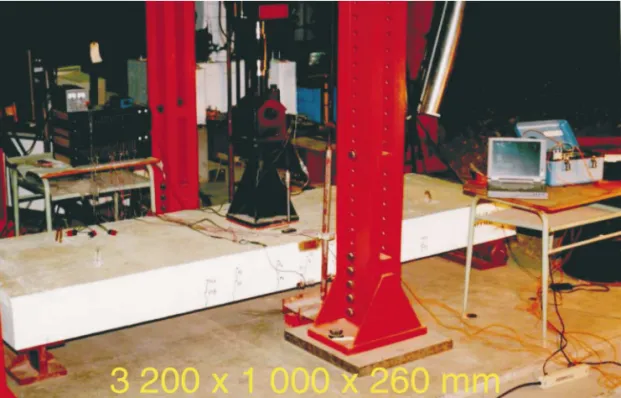
In order to understand the flexural behaviour of the con-crete slab reinforced with CFRP reinforcement, flexure tests
on four one-way concrete slabs of size 3200 × 1000 × 260 mm were performed in the laboratory, as shown in Fig. 2. The slabs were reinforced in the tension zone with ei-ther NEFMAC C16 type grid, NEFMAC C19-R2 type grid, or conventional 15 mm diameter deformed steel rebars. The slabs were extensively instrumented to record the structural response of slabs during the load testing. The slabs were subjected to static and dynamic loading with four million cy-cles. The analysis of the results included crack-width, mid-span deflection, strain in concrete and reinforcement, ulti-mate moment capacity, and failure pattern. Figure 3 shows the crack patterns and failure modes of the slabs. The details of this laboratory investigation were provided in another study (Chekired et al. 1999; Benmokrane et al. 1999). The results available from the study clearly indicated the viabil-ity and effectiveness of CFRP grid reinforcement to be used in reinforced concrete deck slabs. Hence, CFRP NEFMAC
Fig. 3. Crack patterns and failure modes of the slabs.
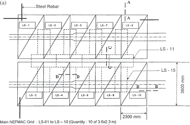
Fig. 5. Structural details of bridge decks: (a) plan view of CFRP grids used in deck slab and (b) cross section of CFRP grid reinforced
C19-R2 was selected as top reinforcement for the concrete deck slabs in the Joffre bridge.
6. Field application
After completion of the laboratory studies and critical analysis of the results, the final process leading toward the field application was initiated. The process involved struc-tural design and detailing, instrumentation, fabrication, and performance monitoring of the actual bridge structure after reconstruction. The complete task was quite elaborate and challenging and required well co-ordinated planning and
management. The descriptions and results presented in the following section bring out various features concerning the field application process.
6.1. Structural design and details
The Joffre bridge consists of five longitudinal spans of different lengths between 26 and 37 m and has four trans-verse spans, each of 3.7 m (Fig. 4). The thickness of the concrete deck slab is 260 mm. The shaded areas of concrete bridge deck, sidewalk, and traffic barrier, as shown in Fig. 4, were selected for the application of FRP reinforcement. The structural design was carried out according to appropriate
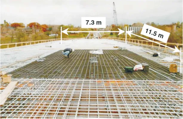
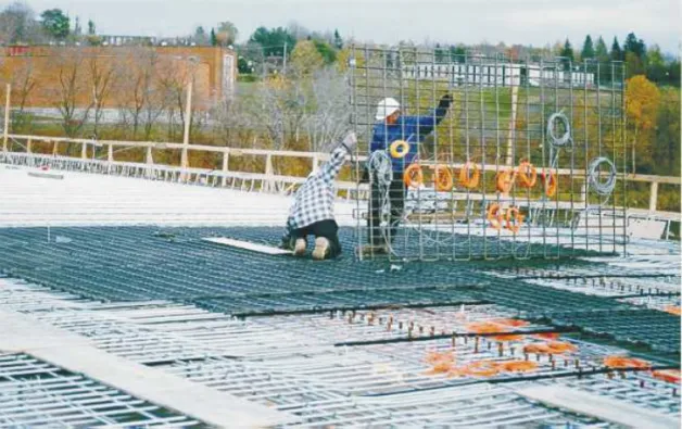
Fig. 6. General view of CFRP grids placed in the bridge deck slab.
guidelines available in the Canadian standard code (CAN3-A23.3-M94, CSA 1994) of practice for conventional steel reinforced concrete structures. However, the change of rein-forcement E-modulus for FRP materials was taken into ac-count.
The selected part of the deck slab (7.3 × 11.5 m) was rein-forced with CFRP reinforcement. The reinforcement near the top surface of the slab was made of CFRP grids but steel rebars were placed at the bottom (Fig. 5). This was done be-cause steel reinforcement at the top face of the deck slab, close to the road surface, is prone to corrosion related dam-age and hence should be replaced with FRP rebars. The main CFRP reinforcement consists of 10 CFRP grids each 3.6 m in length and 2.3 m in width. In addition, a total of 12 CFRP grids of size 2.3 × 1.15 m were used as laps, in both
longitudinal and transverse directions, on the joints of main CFRP reinforcement grids (Fig. 5a). The grids were placed in such a way that the longitudinal spacing was 200 mm and the transverse spacing was 100 mm with reference to the deck slab. The light weight of the FRP reinforcements was very convenient for easy handling and placement during construction. In order to resist the floatation of the light-weight CFRP grid during vibration of fresh concrete, it was tied with plastic chairs, fixed to the bottom steel reinforce-ment, at 2000 mm intervals. The lap splice length between CFRP grid and steel rebar was 700 mm long and that be-tween CFRP grids was 525 mm long (Fig. 5b) to satisfy the basic development length required for the lap joint. Plastic spacer bars were used in the reinforcement splice laps be-tween CFRP and steel rebars to avoid any contact bebe-tween
Fig. 8. GFRP reinforcement in the traffic barrier.
them to prevent the occurrence of galvanic current flow (Fig. 5b). A general view of FRP reinforcements installed in the deck slab can be seen in Fig. 6.
The cross section of a CFRP grid was about 2000 mm2/m
in the transverse direction of the slab (i.e., reinforcement ra-tio 1%). The steel reinforcement used consisted of 15 mm diameter deformed rebars at a spacing 150 mm centre to centre (i.e., reinforcement ratio 0.66%). A concrete cover of 60 and 35 mm at the top and bottom of the slab, respec-tively, was initially recommended for this project, when the deck slab was entirely reinforced with conventional
galva-nised steel rebars. The cover was not changed for the part of the concrete deck slab reinforced with CFRP grids.
A portion of the traffic barrier and the sidewalk (4.75 m) were reinforced with GFRP reinforcement. This reinforce-ment consisted of GFRP straight and bent-up rebars, as shown in Figs. 7 and 8.
6.2. Instrumentation and construction
The bridge was extensively instrumented with several dif-ferent types of gauges. A total of 180 critical locations were identified and instruments (fibre optic sensors, vibrating wire
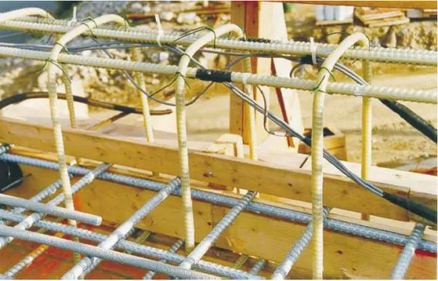
Fig. 10. Instrumented CFRP grid during the installation.
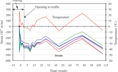
Fig. 12. Data recorded by fibre optic sensors installed on CFRP grid.
strain gauges, and electrical strain gauges) were installed at those locations in the concrete deck slab and on the steel girders. More details on the gauges can be found in Benmokrane et al. (1998).
A number of CFRP reinforcement grids were integrated with fibre optic sensors during the manufacturing process as shown in Fig. 1. This was the first attempt in the world to use integrated fibre optic sensors to monitor the performance of the FRP reinforcement inside the concrete in a bridge structure. Figure 9 shows the schematic depiction of in-stalled gauges on the steel girders and the nine locations of the embedded strain gauges placed inside the concrete.
Figure 10 shows a CFRP reinforcement grid, instrumented with fibre optic sensors and electrical strain gauges, on its way for final placement on the bridge deck. Figure 11 shows placement of ready-mix pumped concrete on the bridge deck.
6.3. Structural performance
Following the successful execution of the construction work, the bridge was opened to traffic on December 5, 1997. Since then static and dynamic responses of different compo-nents of the bridge are being recorded regularly using com-puter-aided data logging systems. Though it is still premature to come to conclusions about the long-term overall service-ability or performance of the structure, the interim results clearly justify the importance and value of this research pro-ject to build confidence about the FRP reinforced concrete
structure and the use of state-of-the-art instrumentation for continuous long-term structural performance monitoring. For instance, Figure 12 shows typical data recorded by fibre op-tic sensors installed on the CFRP grid reinforcement under normal traffic load. The variation of recorded strain with time and temperature clearly indicates that it is possible to obtain meaningful and consistent results from fibre optic sensors and that temperature is the most prominent factor in-fluencing the strain variation in the bridge deck. The analy-sis of all such collected data is currently in progress and will be reported in due course.
6.4. Controlled field tests
Further to monitoring the day-to-day performance of the bridge structure, in November 1998, one year after the open-ing of the bridge to traffic, field dynamic and static tests, us-ing calibrated heavy trucks (Fig. 13), were conducted on the bridge to evaluate the stress level in FRP reinforcement, concrete deck and steel girders. The truck loads were ap-plied to deck spans I (reinforced with CFRP), II, and III. This was done with the realization that loads on span IV and V would not create any additional critical stress effects on the CFRP reinforcements in span I. The weight of a single truck was around 25 tons (245 kN). The maximum com-bined load from front wheels was 8 tons (79 kN) and that for rear wheels was 19 tons (187 kN). Several critical pathways were selected along the span of the bridge deck and the
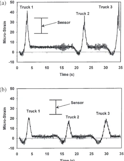
Fig. 14. Strain responses from dynamic load tests of Joffre bridge:
(a) strains recorded at the middle of the web of the girder due to trucks loading (path B) and (b) strains recorded at the middle of the web of the girder due to trucks loading (path C).
Fig. 15. Strain responses from dynamic-calibrated load tests:
(a) strains recorded from two similar tests and (b) strains re-corded at the middle and bottom edge of the steel girder.
truck positions were chosen in such a way to create the max-imum possible stress condition in the bridge deck.
Figure 14a and b shows the results of strains recorded us-ing fibre optic sensors at the middle of the web of steel girder due to movement of trucks loading at paths B and C. The data clearly show that during 35 s, a large strain event (e.g., a truck) followed by two similar strain events (e.g., two consecutive trucks) took place on the bridge. As indi-cated in Fig. 14a and b, the truck produces peak positive strains of about 40 and 20 micro-strain at the middle of the steel girder web, for truck loading on path B and path C, spectively. As shown in Fig. 14b, a closer look at the data re-veals that the strain response at the two locations changes sign between the time periods of about 1 to 3, 14 to 16, and 26 to 28 s. For instance, in Fig. 14b (middle web FOS), neg-ative strain of about 6 micro-strain is observed in the FOS followed by a sharp rise in strain towards the positive direc-tion, eventually peaking at about 20 micro-strain. This can be explained as follows. The steel bridge girder is a continu-ous structure that undergoes compressive strain at the middle and bottom web prior to the truck reaching the sensor loca-tion (half-span, girder I). The truck travelling at about 50– 60 km/h reaches the location directly above half-span girder-I, thus inducing a bend in the beam due to direct loading, which results in positive strain at the middle of the web of the I-beam. A similar argument explains the sensor re-sponses at the bottom of the web of the steel girder.
Figure 15a and b presents strains recorded using fibre op-tic sensors at the middle and bottom of the web of a steel girder due to movement of trucks at several pathways along the bridge deck. The striking similarity in the recorded data at the middle of the beam girder (Fig. 15a) obtained from two similar tests and the higher values of strain recorded at the bottom edge of the girder compared to those recorded at the middle (Fig. 15b) clearly confirm the reliability of the gauges used. Also, at the middle of the web of the girder, higher values of strain were recorded due to truck loading on path B (Fig. 15a), where the truck was moving right above the girder that has the FOS, than that for truck loading on path C (Fig. 15b).
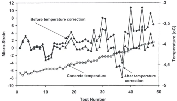
Figure 16 shows typical CFRP reinforcement strain under the static calibrated load test, recorded by the fibre optic sen-sors. It can be seen that, for given calibrated loads, the CFRP reinforcement strain variation is small for similar tests. Figure 17 depicts the variation of strain along the depth of a steel bridge girder due to a truck at position A2 (on path A), B2 (on path B), C2 (on path C), and the com-bined effect A2–B2–C2. Figure 17 reflects two interesting facts. First, the presence of tensile strain throughout the sec-tion depth and at the top of the girder suggests that the effec-tive composite action between the concrete deck and the steel girder did exist. Second, the strain profiles produced by the truck position A2 and C2 were very similar, which re-flected the fact that path A and path C were indeed symmet-rical pathways. Another important feature, seen in Fig. 17, is that the combined load of three trucks on positions A2, B2, and C2 produced the strain values, at the top, middle, and bottom of the steel girder that were approximately the sum-mation of the effects of three individual truck loads. The re-sults show that measured girder steel strains resulting from static tests are less than 120 micro-strain and measured strains in concrete and FRP reinforcements resulting from static tests are very low (less than 20 micro-strain). Once again, these rational observations prove the validity of the results obtained from fibre optic sensors. Additional analysis of the calibrated load results is in progress and will be published in due course. Subsequent calibrated load tests on the bridge will also be carried out at regular interval.
7. Conclusions
The observations and results from the research cum field project reported in this paper can be summarised into the following conclusions:
(1) Application of FRP reinforcement in the construction of a part of the Joffre Bridge has been proved to be very successful to date.
(2) From the construction point of view it was felt by the construction personnel that the lightweight of the FRP
reinforcements were easy to handle and place during construction.
(3) The results show excellent performance of the FRP re-inforced concrete bridge deck and the instruments used. In particular, it is found that the fibre optic sensors are extremely reliable for the short- and long-term monitor-ing of bridge performance.
(4) The preliminary test results indicate that the FRP rein-forcement stresses in the bridge structure are well within their allowable limits.
(5) The results show that measured girder steel strains re-sulting from static tests are less than 120 micro-strain. (6) The results show that measured strains in concrete and FRP reinforcements resulting from static tests are very low (less than 20 micro-strain).
(7) Temperature effects produce the most significant strains in the deck under service conditions.
(8) Fibre optic sensors are suitable for the short- and long-term monitoring of bridge performance.
Acknowledgements
The authors acknowledge and appreciate the close collab-oration of the City of Sherbrooke, the Ministry of Transport of Quebec (MTQ), Teknika Inc., Institute for Research in Construction (NRC, Ottawa), Speco-Engineering Ltd., Roctest Ltd., Fiso Technologies Inc., Autocon Composites Inc., Marshall Industries Composites Inc., Pultrall Inc., and the Network of Centres of Excellence on Intelligent Sensing for Innovative Structures (ISIS Canada). The authors also wish to express their sincere thanks to Dr. Marc Savard, En-gineer at the Ministry of Transport of Quebec (Structures Division), for his help and assistance in conducting cali-brated field tests on the bridge, François Pépin and Jean François Juneau, engineers with Roctest Ltd. (St-Lambert, Quebec), for their help with the instrumentation technique,
and Dr. Gamil Tadros, Technical Application Consultant, ISIS Canada, for his association with the project.
References
Autocon Composites Inc. 1997. Fibre grid reinforcement for con-crete. Technical data collection, Autocon Composites Inc., Weston, Ont.
Benmokrane, B., and Rahman, H. (Editors). 1998. Proceedings of the First International Conference on Durability of Fibre Rein-forced Polymer (FRP) Composites for Construction, Sherbrooke, Qué.
Benmokrane, B., Tighiouart, B., and Chaallal, O. 1996. Bond strength and load distribution of composite FRP rebars in con-crete. ACI Materials Journal, 93(3): 246–253.
Benmokrane, B., Chekired, M., Nicole, J.-F., and Debbache, Z. 1998. Concrete deck slab reinforced with carbon FRP reinforce-ment: Laboratory tests and application to Joffre Bridge (in French). Technical Report No. 1, Contract: 1220-97-BD07, sub-mitted to the Ministère des Transports du Québec, Qué. Benmokrane, B., Masmoudi, R., Chekired, M., Rahman, H.,
Debbache, Z., and Tadros, G. 1999. Design, construction, and monitoring of fiber reinforced polymer reinforced concrete bridge deck. Fourth International Symposium on Fiber Reinforced Poly-mer Reinforcement for Reinforced Concrete Structures. APoly-merican Concrete Institute, SP-188, Baltimore, Md., pp. 87–101. Chekired, M., Masmoudi, R., Debbache, Z., and Benmokrane, B.
1999. Concrete deck slab reinforced with carbon FRP reinforce-ment: Laboratory tests and application to Joffre Bridge (in French). Technical Report No. 2, Contract: 1220-97-BD07, sub-mitted to the Ministère des Transports du Québec, Qué. CSA. 1994. Design of concrete structures for buildings. Standard
CAN3-A23.3-M94, Canadian Standards Association, Rexdale, Ont. El-Badry, M.M. (Editor). 1996. Advanced composite materials in bridges and structures. Canadian Society for Civil Engineering, Montréal, Qué.
GangaRao, H.V.S., Thippesway, H.K., Kumar, S.V., and Franco, J.M. 1997. Design, construction and monitoring of the first FRP
reinforced concrete bridge deck in the United States. Proceed-ings of the Third International Symposium (FRPRCS-3) on Non-Metallic (FRP) Reinforcement for Concrete Structures, Sapporo, Japan, Vol. 1, pp. 647–656.
Japan Concrete Institute. (Editor). 1997. Proceedings of the Third International Symposium (FRPRCS-3) on Non-Metallic (FRP) Reinforcement for Concrete Structures, Sapporo, Japan, Vol. 1. Masmoudi, R., Thériault, M., and Benmokrane, B. 1998. Flexural behaviour of concrete beams reinforced with deformed FRP C-BAR reinforcing rods. ACI Structural Journal, 95(6): 665–676. Masmoudi, R., Béland, S., and Benmokrane, B. 1999.
Experimen-tal evaluation of Kb factor for glass and carbon isorod FRP rebars. Technical Report No. 02-1999, submitted to Pultrall Inc., Thetford Mines, Qué.
Neale, K.W., and Labossière, P. (Editors). 1992. Proceeding of the First International Conference on Advanced Composite Mate-rials in Bridges and Structures, Sherbrooke, Qué.
Rizkalla, S., and Tadros, G. 1994. First smart bridge in Canada. ACI Concrete International, (16) 6: 42–44.
Rizkalla, S., Shehata, E., and Abdelrahman, A. 1998. Design and con-struction of a highway bridge reinforced for shear and prestressed by CFRP. American Concrete Institute Seminar on Field Applications of FRP Reinforcement to Concrete: Parts I and II, Atlanta, Ga. Saadatmanesh, H., and Ehsani, M.R. (Editors). 1996. International
Conference on Composites for Infrastructure. Proceeding of the International Conference on Composites in Infrastructure, Tuc-son, Ariz.
Taerwe, L. (Editor). 1995. Proceedings of the Second International RILEM Symposium (FRPRCS-2) on Non-metallic (FRP) Rein-forcement for Concrete Structures. E & FN Spon, London, U.K. Thériault, M., and Benmokrane, B. 1998. Effects of FRP
reinforce-ment ratio and concrete strength on the flexural behaviour of concrete beams. ASCE Journal of Composites for Construction,