Publisher’s version / Version de l'éditeur:
Vous avez des questions? Nous pouvons vous aider. Pour communiquer directement avec un auteur, consultez la première page de la revue dans laquelle son article a été publié afin de trouver ses coordonnées. Si vous n’arrivez pas à les repérer, communiquez avec nous à PublicationsArchive-ArchivesPublications@nrc-cnrc.gc.ca.
Questions? Contact the NRC Publications Archive team at
PublicationsArchive-ArchivesPublications@nrc-cnrc.gc.ca. If you wish to email the authors directly, please see the first page of the publication for their contact information.
https://publications-cnrc.canada.ca/fra/droits
L’accès à ce site Web et l’utilisation de son contenu sont assujettis aux conditions présentées dans le site LISEZ CES CONDITIONS ATTENTIVEMENT AVANT D’UTILISER CE SITE WEB.
Internal Report (National Research Council of Canada. Institute for Research in Construction), 1995-06
READ THESE TERMS AND CONDITIONS CAREFULLY BEFORE USING THIS WEBSITE. https://nrc-publications.canada.ca/eng/copyright
NRC Publications Archive Record / Notice des Archives des publications du CNRC :
https://nrc-publications.canada.ca/eng/view/object/?id=38d36cc0-c931-463b-b8ff-49c8b9dc805b https://publications-cnrc.canada.ca/fra/voir/objet/?id=38d36cc0-c931-463b-b8ff-49c8b9dc805b
NRC Publications Archive
Archives des publications du CNRC
For the publisher’s version, please access the DOI link below./ Pour consulter la version de l’éditeur, utilisez le lien DOI ci-dessous.
https://doi.org/10.4224/20375221
Access and use of this website and the material on it are subject to the Terms and Conditions set forth at
Experimental Studies on the Fire Resistance of Circular Hollow Steel Columns Filled with Steel-Fibre-Reinforced Concrete
z.2, " -
o m 6'31 Institute for lnstitut de
I;?! e Research in recherche en
- ... Construction construction .-HI
s+ .>
.
.
., 7 National Research Conseil national1;
L . 3 i?i- , .:
If
1
Council Canada de recherches Can-;I ,U
Experimental Studies on the Fire
Resistance of Circular Hollow
Steel Columns Filled with
Steel-Fibre-Reinforced Concrete
by V.K.R. Kodur and T.T. Lie
Internal Report No. 691
Date of issue: June 1995
This is an internal report of the Institute for Research in Construction. Although not intended for general distribution, it may be cited as a reference in other publications.
EXPERIMENTAL STUDIES ON THE FIRE RESISTANCE OF CIRCULAR HOLLOW STEEI. COI.UMNS FILLED WITH STEEL-FIBRE-REINFORCED
CONCRETE
V.K.R. Kodur and T.T. Lie ABSTRACT
Tests were canied out to determine the fire resistance of circular hollow steel columns filled with steel-fibre reinforced concrete. The results of six full-scale fire resistance tests are described in this report. The main study variables were the column dimensions and load intensity. These studies were conducted as part of a research program aimed at developing simple design equations capable of predicting the fire resistance of concrete-filled hollow steel columns.
EXPERIMENTAL STUDIES ON THE FIRE RESISTANCE OF CIRCULAR HOLLOW STEEL COLzUMNS FILLED WITH STEELFIBRE-REINFORCED
CONCRETE
V.K.R. Kodur and T.T. Lie
1. INTRODUCTION
Circular hollow steel sections are very efficient structural sections in resisting compression loads. By filling these hollow steel columns with concrete, the load-canying capacity of these columns can be increased substantially. In addition, a high fire resistance can be obtained without using surface fire protection for the steel. The elimination of such surface protection. in tum, increases space in the building and improves the architectural aesthetics. Also, the fact that formwork is not required provides a significant saving in construction cost and time.
These benefits have stimulated research into the structural and fire resistance performance of concrete-filled hollow steel sections in several laboratories around the world. For a number of years, the National Fire Laboratory of the Institute for Research in Construction, National Research Council of Canada (NRCC), has been engaged in studies aimed at developing methods for predicting the fire resistance of concrete-filled steel columns. Both experimental and numerical studies on the fire resistance of hollow steel columns filled with concrete were canied out with the support of the Canadian Steel Construction Council (CSCC) and the American Iron and Steel Institute (AISI).
Three types of concrete filling, namely plain, bar-reinforced and fibre-reinforced concrete. were considered in the study. Studies on hollow steel columns filled with plain concrete and bar-reinforced concrete were completed [I. 2,3,4] and the work on HSS columns filled with steel-fibre-reinforced concrete is at
an
advanced stage.This report deals with circular hollow steel columns filled with fibre-reinforced concrete. The results of six fire resistance tests on full-size circular columns are described in detail, including the column temperatures, axial deformations and fire resistances.
2. TEST SPECIMENS
2.1 Dimensions
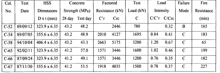
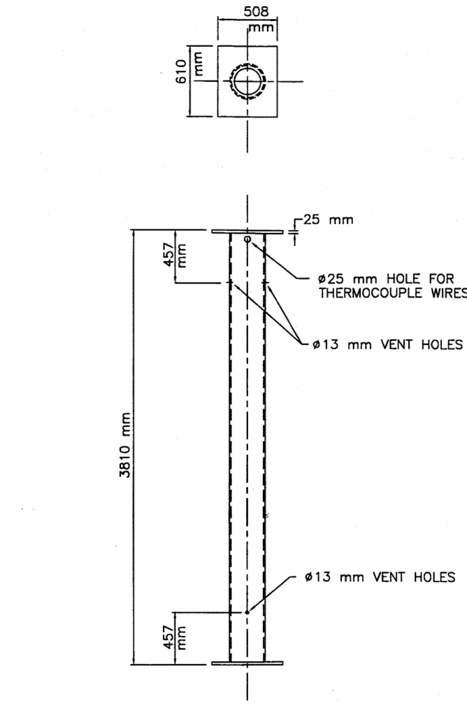
All six columns were 3810 mrn long from end plate to end plate and were of circular cross section. The outside diameter, D, of the columns ranged from 323.9 mm to 406.4 mm. The wall thickness, t. of all six sections was 6.35 mm. The dimensions of each column are listed in Table 1.
2.2 Materials
Steel hollow structural sections (HSS) meeting the requirements of CSA Standard G40.20-M81 [5], Class H, were used. The sections were made with Grade 300W steel which had a minimum yield strength of 300 MPa. The sections were supplied by Stelco Inc. The end plates were constructed using mild steel.
2.2.2 Concrete
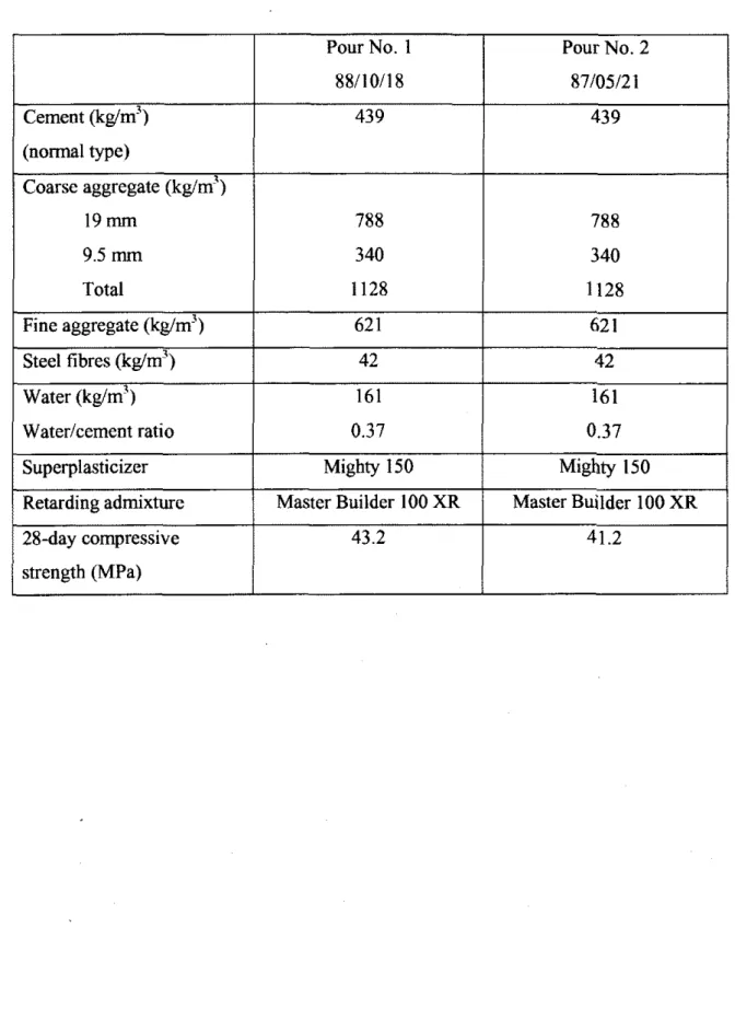
Two batches of concrete mix were supplied by Dufferin Concrete from Ottawa. Columns C-52. C-54 and C-58 were cast from the first batch while the other three columns, C-65, C-66 and C-67, were cast from the second batch of concrete. The mixes wcrc made with gener~l purpose Type 10 Portland cement, carbonate stone and silica based sand. RIBTEC steel fibres of XOREX type, supplied by Ribbon Technology Corporation [6], were used as reinforcement. The fibres, which were 50 mm long and 0.9 mm equivalent diameter, had an aspect ratio of 57. The percenttge of steel fibres in the concrete mix was 1.76% by mass. Superplasticizer, Mighty 150 , and retarding admixtures, Master Builder 100 XR , were added to the mix to improve workability. Batch quantities of the concrete are given in Table 2. The 28-day cylinder compressive strengths were 43.2 and 41.2 MPa, respectively.
2.3 Fabrication
2.3.1 Steel Column
The hollow steel sections were fabricated by cutting the supplied scctions to 3797 mm in Icngth. Stccl end platcs wcrc thcn welded ro both scction cxtrcmitics. with spccial attcntioibciny given to thc centering and pcrpcndicularity of the end platcs. The total column lcngh was 3810 mm including end plates.
The hollow steel sections and end plates were first joined by a groove weld. Secondly, a fillet weld was added around the outside diameter of the hollow steel section. AWS 5.1 8 Type E705-6 welding rods were used for both welds. Figure 1 shows
elevation and cross-sectional details of a typical column.
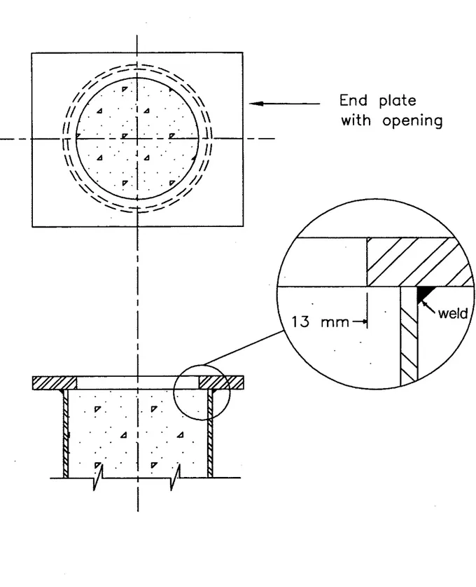
Before assembly. a hole was cut in each plate to provide an opening through which the concrete was poured. The hole was approximately 25 mrn smaller in diameter than the inside diameter of the section. This construction provided a 13 mm lip to transfer the load from the steel plate to the concrete filling. The end plate connection detail is shown in Figure 2.
Five small holes were drilled in the wall of the steel sections (see Figure 1). Two pairs, 13 mm in diameter, located 457 mrn from each end of the columns, were provided as vent holes for the water vapour produced during the experiment. The fifth hole, 25 mm in diameter, located near the top end plate, was used for entry of thermocouple wires. 2.3.2 Concrete Placement
The concrete was mixed in a truck mixer. The steel fibres were added to the fresh concrete and mixed for approximately 5 minutes to provide uniform dispersion. The columns were put in an upright position and filled with the concrete. A concrete
placement bucket and a funnel were used to deposit the concrete in the steel column. An internal vibrator was used to consolidate the concrete inside the column. The top surface of the column was finished with a small trowel. The section was sealed at both ends with plastic sheet and tape to avoid possible moisture leaks. The columns were left upright for 28 days. then stored horizontally at room temperature, with no particular curing measures
I Certain commercial products are identified in this paper in order to adequately
specify the experimental details. In no case does such identification imply recommendation or endorsement by the National Research Council of Canada, nor does it imply that the product or material identified is the best available for the purpose.
being taken, until the test date. In general, six months or more elapsed between the time a column was poured and the time it was tested. However, for Column C-66, the curing period was limited to four months.
Before each test, the mojsture condition in the centre of a column section was measured by inserting a Vaisala moisture sensor in a hole drilled in the concrete through one of the vent holes. In general, a moisture content, corresponding to approximately 85 to 95% relative humidity, was measured.
2.3.3 Instrumentation
Type K chromel-alumel thermocouples, with a thickness of 0.91 mm. were used for measuring concrete temperatures at several locations across the mid-height section of the columns. The thermocouples were tied to a steel rod that was secured to a bar running along the longitudinal axis of the column. The bar was fixed at both ends of the column as shown in Figure 3. In addition, a thermocouple was attached to the steel wall of each column at mid-height. The thermocouple locations are shown in Figure 4.
3. TEST APPARATUS
The tests were canied out by exposing the columns to heat in a furnace specially built for testing loaded columns and walls. The test furnace was designed to produce conditions to which a member might be exposed during a fire, i.e., temperatures, structural loads and heat transfer. It consisted of a steel framework supported by four steel columns, with the furnace chamber inside the framework (Figure 5). The characteristics and
instrumentation of the furnace are described in detail in Reference [7]. Only a brief description of the furnace and the main components is given here.
3.1 Loading Device
A hydraulic jack with a capacity of 9778 kN produces a load along the axis of the test column. The jack is located at the bottom of the furnace chamber. Eccentric loads can be applied by means of hydraulic jacks, one at the top and one at the bottom of the column. located at a distance of 508 mm from the axis of the column. The capacity of the top jack is 587 kN and that of the bottom jack is 489 kN.
3.2 Furnace Chamber
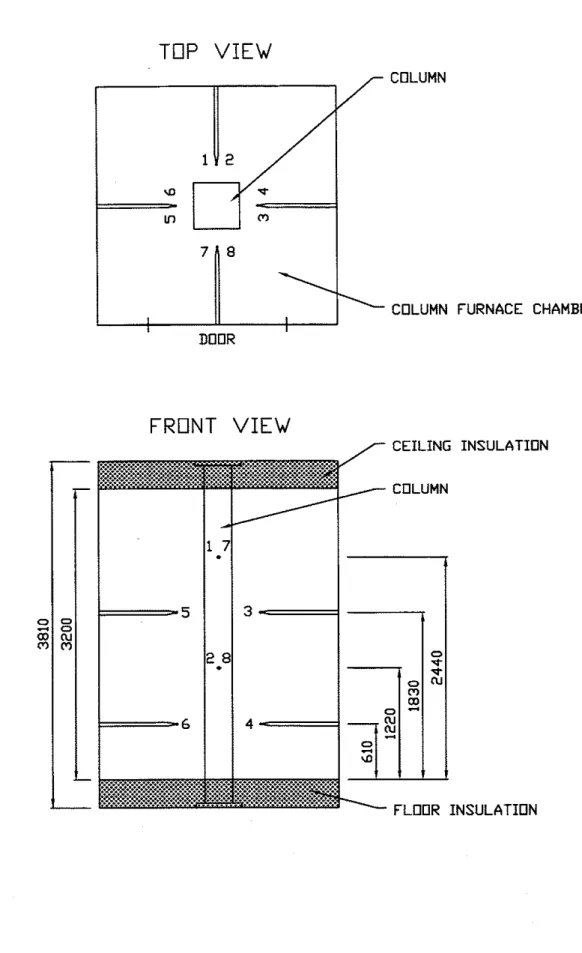
The fumace chamber has a floor area of 2642 x 2642 mm and is 3048 mm high. The interior of the chamber is lined with insulating materials that efficiently transfer heat to the specimen. The ceiling and floor insulation protects the column end plates from fire. It should be noted that only 3200 mm of the column is exposed to fire.
There are 32 propane gas burners in the furnace chamber, arranged in eight columns containing four burners each. The total capacity of the bumers is 4700 kW. Each burner can be adjusted individually, which allows for a high degree of temperature uniformity in the furnace chamber. The pressure in the furnace chamber is also adjustable and was set somewhat lower than atmospheric pressure.
4
3.3 Instrumentation
The furnace temperatures were measured with the aid of eight chromel-alumel thermocouules. The thermocou~le iunctions were located 305 mm from the test specimen, i t various heights. ~wo'ihermocou~les were placed opposite each other at intervals of 610 mm along the height of the furnace chamber. The locations of their junctions and their numbering are shown in Figure 6. Thermocouples 4 and 6 were
located at a height of 610 mm from the floor, Thermocouples 2 and 8 at 1220 mrn, Thermocouples 3 and 5 at 1830 mm and Thermocouples 1 and 7 at 2440 mm. The temperatures measured by the thermocouples were averaged automatically and the average temperature was used to control the furnace temperature.
The loads were controlled by servocontrollers and measured with pressure
transducers. The accuracv of controlling and measuring loads is about 4 kN at lower load
-
levels and relatively bette; at higher load-s.The axial deformation of the test columns was determined by measuring the displacement of the jack that supports the column. The rotation of the end plates of the columns was determined by measuring the displacement of the plates at a distance of 500 mm from the centre of the hinge at the top and bottom respectively. The
displacements were measured using transducers with an accuracy of 0.002 mm.
4. TEST CONDITIONS AND PROCEDURES
4.1 End Conditions
Five columns were tested with both ends of the column fixed, i.e. restrained against rotation and horizontal translation. For this purpose, eight 19 mm diameter bolts spaced regularly around the column, were used at each end to bolt the end plate to the loading head at the top and the hydraulic jack at the bottom. Column C-52 was tested under hinged end conditions, i.e., with restraint against horizontal translation only. The hinged condition was obtained by bolting the end plates to the receiving plate with a roller bearing at each end.
4.2 Loading
All columns were tested under a concentric load, except Column C-52 where the load was eccentric by 25
mm.
The applied load on the columns ranged from 32 to 67% of the factored compressive resistance of the columns (C,) or 70 to 120% of the factored compressive resistance of the concrete core (C',), determined according to CSA Standard CSNCAN-S 16.1-M89 [a]. The factored compressive resistances of each column, as well as the applied loads. are given in Table 1. The factored compressive resistances of the columns were calculated using the effective length factors, K, recommended inCSA/C.AN-S 16.1-M89 for the given end conditions, i.e., 0.65 for fixed ends and 1 for pinned ends.
All loads were applied approximately 45 minutes before the start of the test and were maintained until a condition was reached at which no further increase of the axial and rotational deformations could be measured. This condition was selected as the initial condition of the column deformations. The load was maintained constant throughout the test.
4.3 Fire Exposure
The ambient tcmperature at the start of each test was approximately 20°C. During the test. the column was exposed to heating controlled in such a way that the average temperature in the furnace followed, as closely as possible, the CANKJLC-SIOI [9] or ASTM-El19 [lo] standard temperature-time curve. This curve can be calculated using the following equation:
where: t = time in hours
Tf = tcmperature of fumace in "C 4.4 Recording of Results
The furnace, concrete and steel temperatures, as well as axial deformations of the columns. were recorded at two-minute intervals. In the case of the eccentrically loaded column test, the lateral deflection of the column at mid-height and the rotation of the end plates of the column were measured with varying frequencies, depending on the rate of change of the measured quantities.
4.5 Failure Criterion
The columns were considered to have failed, and the tests were terminated, when the axial hydraulic jack, which has a maximum speed of 76 rndmin, could no longer maintain the load. Generally, the failure of the columns, which was determined by visual observation. was in compression. However, bending was observed for Column C-52 which had an eccentric loading, This column failed by buckling.
5. RESULTS AND DISCUSSION
The results of the six column tests are summarized in Table 1, in which the column characteristics, test conditions, fire resistances and failure modes are given for each
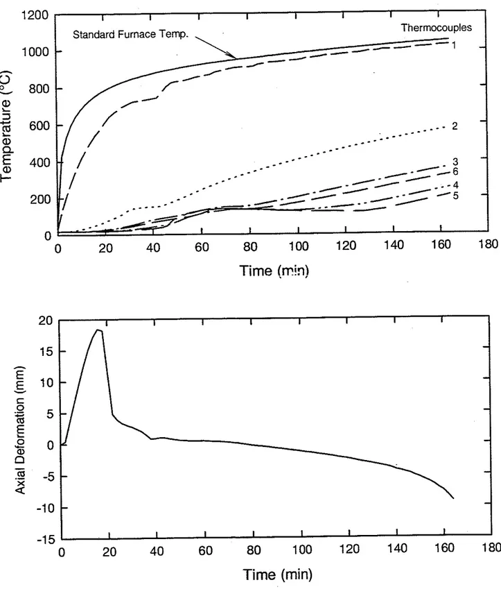
column. The furnace, concrete and steel temperatures recorded during the tests, as well as the axial deformations of the column specimens, are given in Tables A1 to A6 and plotted in Figures A1 to A6, in Appendix A. Positive axial deformation values indicate expansion of the column. Figures
B1
to 8 6 in Appendix B show photographs of the columnspecimens after the fire tests.
Data from the tests indicate that fire resistances up to three hours can be obtained for circular HSS columns filled with fibre reinforced concrete. In contrast, the fire resistance of HSS columns filled with plain concrete is limited to one to two hours [3]. The results for Column C52 also indicate that a high fire resistance can be obtained under eccentric loads. The fire resistance of Column C58 was only 65 minutes. This could be due to the high load intensity used for this particular column. The five columns, subjected to axial loading, failed in compression mode, while Column C-52, which was subjected to eccentric loading, failed in buckling mode.
The increased fire resistance of fibre-reinforced concrete-filled columns, as compared to plain concrete-filled columns [I], can be attributed to superior mechanical properties of fibre-reinforced concrete. Results from the experimental studies camed out to determine mechanical properties at elevated temperatures [I 11 indicate that the
400°C. The steel fibres prevented early cracking and also contributed to the compressive strength of concrete at elevated temperatures.
These fire tests were canied out in order to validate mathematical models capable of predicting the fire resistance of HSS columns filled with fibre-reinforced concrete. The development of such method? is currently in progress. The mathematical models will be used to conduct detailed parametric studies in order to determine the influence of various parameters on the fire resistance of HSS columns filled with fibre reinforced concrete. In the interim, the test results given in this rcport can be used for assessing the fire resistance of HSS columns filled with fibre-reinforced concrete that lie within the range of the variables examined in this study.
REFERENCES
1. Lie, T.T. and Chabot. M., Experimental Studies on the Fire Resistance of Hollow Steel Columns Filled with Plain Concrete, IRC Internal Report No. 61 1, National Research Council of Canada, Institute for Research in Construction, Ottawa, Ontario. 1992.
2. Chabot, M. and Lie, T.T., Experimental Studies on the Fire Resistance of Hollow Steel Columns Filled with Bar-Reinforced Concrete, IRC Intemal Report No. 628, National Research Council of Canada, Institute for Research in Construction, Ottawa, Ontario, 1992.
3. Lie, T.T. and Chabot, M., A Method to Predict the Fire Resistance of Circular Concrete Filled Hollow Steel Columns, Joumal of Fire Protection Engineering, 2(4),
1990 nn 111-126
--.-, rr' -: -
4. Lie, T.T., Flre Res~stance of Circular Steel Columns Filled with Bar-Reinforced Concrete, ASCE Joumal of Structural Engineering, 120(5), May 1994, pp. 1489-
i
.<",.
sns5. General Requirement for Rolled or Welded Structural Quality Steels - G40.20-M81,
Canadian Standards Association, Toronto, Canada, 198 1.
6. RIBTEC, Carbon Steel Fibres for Concrete Reinforcement, Ribbon Technology Corporation, Gahanna, Ohio, U.S.A.
7. Lie, T.T., New Facility to Determine Fire Resistance of Columns, Canadian Joumal of Civil Engineering, 7(3), 1980, pp. 551-558.
8. Limit States Design of Steel Structures, CANICSA-S 16.1-M89, Canadian Standards Association, Toronto, Canada, 1989.
9. Standard Methods of Fire Endurance Tests of Building Construction and Materials, CAN/ULC-S 10 1. Underwriters' Laboratories of Canada, Scarborough, Canada,
1
.
O R 9 ,.,,.10. Standard Mcthods of Firc Tests on Building Construction and Materials, ASTM El 19-88. American Societv for Testing and Materials, Philadelphia, PA, USA. 1990. 11. Lie, T.T: and Kodur, v.K.R., ~ e c h a n k a l Properties of ~ibre-~einforced Concrete
at Elevated Temperatures, IRC Internal Report No. 687, National Research Council of Canada, Institute for Research in Construction, Ottawa, Ontario, 1995.
Table 1. Summary of test parameters and results
No.
I
Date/
DimensionsI
Strength (MPa) D x t (mm) 28 day Test day C-52 89/09/12 323.9 x 6.35 43.2 48.2Concrete HSS
Col.
Resistance (kN)
I
Load (kN)I
IntensityI
ModeI
ResistanceI
FactoredTest
Factored Resistance
C'r = Factored compressive resistance of concrete core of the column according to CAN3-S 16.1-M89 Crc = Factored compressive resistance of concrete-filled HSS column according to CAN3-S16.1-M89 Failure Mode
B
= Buckling C = compressionTable 2. Batch quantities for concrete mix Pour No. 1 (normal type) Coarse aggregate (kg/m7) Cement (kg/m3) Total Fine aggregate (kg/m3) Steel fibres (kg/m3) Water (kg/m3) 88110118 43 9 Waterlcement ratio Superplasticizer Retarding admixture 28-day compressive strength (MPa)
1
Mighty 150 Master Builder 100 XR Pour No. 2 87/05/21 42 161 0.37 Mighty 150 Master Builder 100 XR 41.2SECTION A-A
TOP
VIEW
DOOR COLUMN \D-
mFRONT
VIEW
CEILING INSULATION FLOOR INSULATIONFigure 6. Loeation of themocouples
in
furnace chamberCOLUMN FURNACE CHAMBER
7 6 8
APPENDMA
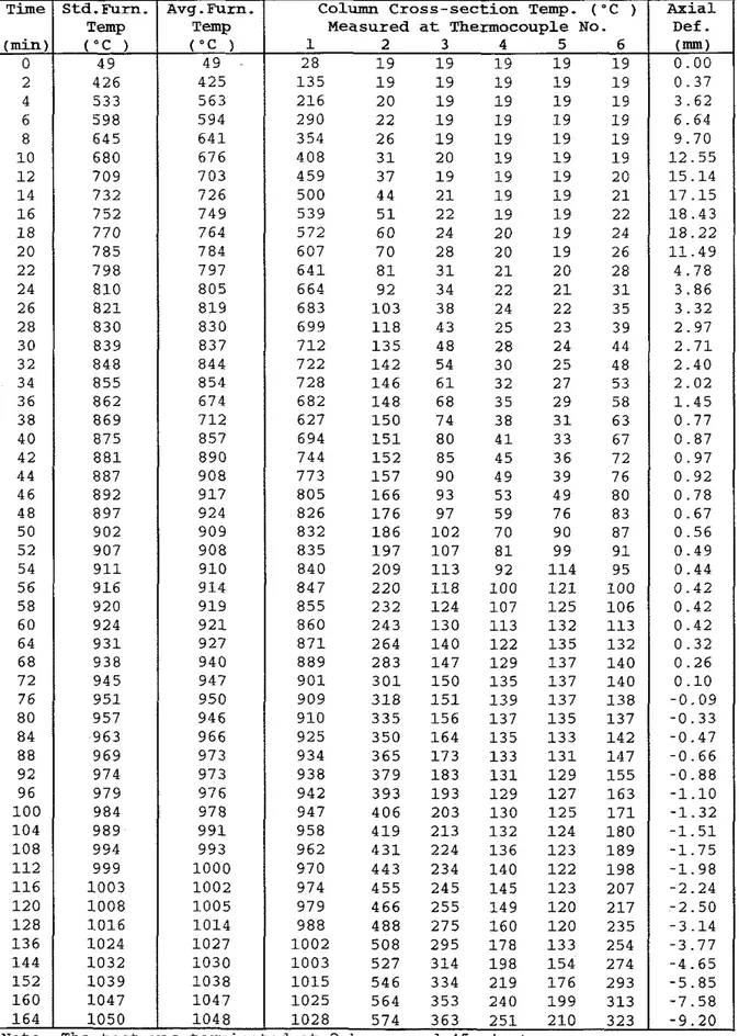
Table A 1 Temperatures and Axial Deformation of Column No. C-52
I
~ i m eI
Std. Furn.I
Avg. Furn.I
Column Cross-section Temp. ('C )1
A x i a l(min) 1 3 5 1 9 1 9 1 9 1 9 216 2 0 1 9 1 9 1 9 290 2 2 1 9 1 9 1 9 354 2 6 1 9 1 9 1 9 4 0 8 3 1 20 1 9 1 9 459 3 7 1 9 1 9 1 9 500 44 2 1 1 9 1 9 539 5 1 22 1 9 1 9 5 7 2 6 0 24 2 0 1 9 607 7 0 2 8 20 1 9 6 4 1 8 1 3 1 2 1 2 0 664 9 2 3 4 2 2 2 1 6 8 3 1 0 3 38 24 2 2 699 1 1 8 4 3 25 23 7 1 2 1 3 5 48 28 24 7 2 2 1 4 2 54 30 2 5 7 2 8 1 4 6 6 1 32 2 7 682 1 4 8 68 3 5 2 9 627 1 5 0 74 3 8 3 1 694 1 5 1 8 0 4 1 3 3 744 1 5 2 8 5 4 5 36 7 7 3 1 5 7 9 0 49 3 9 8 0 5 1 6 6 9 3 5 3 4 9 8 2 6 1 7 6 97 5 9 7 6 8 3 2 1 8 6 1 0 2 70 9 0 8 3 5 1 9 7 1 0 7 8 1 9 9 8 4 0 2 0 9 1 1 3 92 1 1 4 8 4 7 2 2 0 1 1 8 1 0 0 1 2 1 8 5 5 232 1 2 4 1 0 7 1 2 5 860 2 4 3 1 3 0 1 1 3 1 3 2 8 7 1 264 1 4 0 1 2 2 1 3 5 8 8 9 2 8 3 1 4 7 1 2 9 1 3 7 9 0 1 3 0 1 1 5 0 1 3 5 1 3 7 909 3 1 8 1 5 1 1 3 9 1 3 7 910 3 3 5 1 5 6 1 3 7 1 3 5 9 2 5 3 5 0 1 6 4 1 3 5 1 3 3 934 3 6 5 1 7 3 1 3 3 1 3 1 938 3 7 9 1 8 3 1 3 1 1 2 9 942 3 9 3 1 9 3 1 2 9 1 2 7 947 4 0 6 2 0 3 1 3 0 1 2 5 9 5 8 4 1 9 2 1 3 1 3 2 1 2 4 9 6 2 4 3 1 224 1 3 6 1 2 3 9 7 0 4 4 3 234 1 4 0 1 2 2 974 4 5 5 2 4 5 1 4 5 1 2 3 9 7 9 4 6 6 2 5 5 1 4 9 1 2 0 9 8 8 4 8 8 2 7 5 1 6 0 1 2 0 1 0 0 2 5 0 8 2 9 5 1 7 8 1 3 3 1 0 0 3 5 2 7 3 1 4 1 9 8 1 5 4 1 0 1 5 5 4 6 334 219 1 7 6 1 0 2 5 5 6 4 3 5 3 240 1 9 9 1 0 2 8 5 7 4 3 6 3 2 5 1 210
ed at 2 hours and 4 5 minutes
80 84 8 8 92 9 6 1 0 0 1 0 4 1 0 8 1 1 2 1 1 6 1 2 0 1 2 8 1 3 6 1 4 4 1 5 2 1 6 0 1 6 4 0 I 49 49 1 2 8 1 9 1 9 1 9 1 9 1 9 1 0 . 0 0 Temp ( " C ) 957 963 969 974 979 984 989 994 999 1 0 0 3 1 0 0 8 1 0 1 6 1 0 2 4 1 0 3 2 1 0 3 9 1 0 4 7 1 0 5 0
Note: The test was T-P
("C )
Measured at Thermocouple No.
1 2 3 4 5 6
Def
.
(mm)0
0 20 40 60 80 100 120 140 160 180
Time @?in)
I I I I I I I I
Standard Furnace Temp. Thermocouples
-
-
-
-
_ _ _ - - - -
2_ _ _ . - -
_ _ _ - - -
_ _ _ - - -
-
_ - - -
- 3I
-
_ - - -
-.
---6 . . - 4-
---
/>
/ - 5 - C I I I ITime (min)
TABLE A2 Temperatures and Axial Deformation of Column No. C - 5 4 2 426 4 5 3 3 6 5 9 8 8 6 4 5 1 0 680 1 2 709 1 4 732 1 6 7 5 2 1 8 7 7 0 2 0 7 8 5 22 7 9 8 24 810 2 6 8 2 1 2 8 830 3 0 8 3 9 3 2 8 4 8 3 4 8 5 5 3 6 8 6 2 3 8 8 6 9 4 0 875 4 2 8 8 1 4 4 8 8 7 46 892 4 8 897 5 0 902 5 2 907 54 9 1 1 5 6 916 5 8 920 6 0 924 6 4 9 3 1 6 8 938 7 2 9 4 5 7 6 9 5 1 8 0 957 84 963 8 8 969 9 2 974 96 979 1 0 0 984 1 0 4 989 1 0 8 994 1 1 2 999 1 1 6 1 0 0 3 1 2 0 1 0 0 8 1 2 8 1 0 1 6 136. 1 0 2 4 1 4 4 1 0 3 2 1 5 2 1 0 3 9 1 6 0 1 0 4 7 1 6 8 1 0 5 4 1 7 6 1 0 6 1 1 8 2 1 0 6 6
Note: The test
1 0 8 8
1
1 0 4 3 554 316 208as terminated at 3 hours and 2 minutes
A x i a l
Def. Column Cross-section Temp.("C )
Measured at Thermocouple No. Time s t d . ~ u m .
Temp
Avg.Furn. Temp
1200 1 I I I I I I I I
Standard Furnace Temp. T h e r ~ c o u p l e S
1000
-
-
-
2-
0 20 40 60 80 100 120 140 160 180 200Time (min)
Time
(min)
Table A3 Temperatures and Axial Deformation o f Column No. C-58 Axial Def
.
( m ) 0 . 0 0 0 . 5 9 0 . 7 8 0 . 7 9 0 . 7 9 0 . 7 9 0 . 7 3 0 . 5 1 0 . 2 4 - 0 . 0 6 - 0 . 3 6 - 0 . 6 0 - 0 . 7 7 - 0 . 9 7 - 1 . 2 4 - 1 . 4 9 - 1 . 7 5 - 2 . 0 6 - 2 . 3 5 - 2 . 6 1 - 2 . 8 5 - 3 . 0 9 - 3 . 3 4 - 3 . 5 8 - 3 . 8 3 - 4 . 0 7 - 4 . 3 1 - 4 . 5 7 - 4 . 8 7 - 5 . 1 7 - 5 . 5 3 - 6 . 0 3 - 6 . 7 6 - 4 0 . 8 3 Time (min) 0 2 4 6 8 1 0 1 2 1 4 1 6 1 8 2 0 2 2 2 4 2 6 2 8 3 0 3 2 3 4 3 6 3 8 4 0 4 2 4 4 4 6 4 8 5 0 5 2 54 5 6 5 8 6 0 62 64 6 6 A v g . F u m . Temp ('C ) 4 9 3 8 4 5 7 0 6 3 3 6 4 7 6 7 5 7 0 6 7 2 3 7 4 7 7 6 3 7 7 8 7 8 1 7 8 2 8 1 1 8 3 4 8 3 9 8 4 4 8 4 7 8 6 3 8 6 7 8 6 9 8 8 0 8 8 2 8 9 1 8 9 5 9 0 0 9 0 5 9 1 0 9 0 9 9 1 7 9 2 5 9 2 3 9 3 2 9 2 7 Std.Furn. Temp ( e C ) 5 1 3 8 7 5 7 2 6 3 2 6 4 7 6 7 6 7 0 7 7 2 4 7 4 8 7 6 3 7 8 0 7 8 1 7 8 3 8 1 2 8 3 2 8 3 8 8 4 5 8 4 8 8 6 4 8 6 8 8 7 0 8 8 1 8 8 4 8 9 2 8 9 7 9 0 1 9 0 6 9 1 1 9 1 0 9 1 8 9 2 6 9 2 3 9 3 3 9 2 8Column Cross-section Temp. ( " C )
Measured at Thermocouple No.
1 2 3 4 5 6 2 5 1 4 1 4 1 4 1 5 1 5 1 4 9 1 4 1 4 1 4 1 4 1 4 2 6 9 1 4 1 4 1 4 1 4 1 4 3 6 2 1 4 1 4 1 4 1 4 1 4 4 2 5 1 4 1 4 1 4 1 4 1 4 4 7 7 1 5 1 4 1 4 1 4 1 5 5 2 2 1 5 1 4 1 4 1 4 1 5 5 5 4 1 6 1 4 1 4 1 4 1 5 5 8 3 1 8 1 4 1 4 1 5 1 5 6 1 1 1 9 1 5 1 5 1 5 1 5 6 3 3 2 1 1 5 1 5 1 5 1 5 6 4 7 2 4 1 5 1 5 1 5 1 6 6 2 3 2 7 1 6 1 5 1 6 1 6 6 6 4 3 1 1 7 1 6 1 6 1 7 7 0 5 3 5 1 8 1 7 1 7 1 8 7 3 2 4 1 1 9 1 8 1 7 1 9 7 4 5 5 0 2 1 1 9 1 8 2 0 7 5 5 6 1 2 2 2 0 1 9 2 2 7 7 5 8 0 2 4 2 1 2 1 2 3 7 9 2 9 8 2 6 2 2 2 2 2 6 8 0 5 1 0 5 2 8 2 4 2 4 2 8 8 1 7 1 1 6 3 2 2 6 2 6 3 0 8 2 9 9 4 3 5 2 8 2 8 3 2 8 4 1 7 8 3 8 3 1 3 0 34 8 5 2 6 0 4 3 3 3 3 1 3 6 8 6 1 5 1 5 0 3 8 3 4 3 8 8 6 6 5 2 6 1 5 1 4 1 4 3 8 6 9 7 0 7 1 6 4 6 0 6 3 8 7 1 1 0 3 7 8 7 3 7 7 9 0 8 7 9 1 0 6 8 4 7 9 8 5 9 5 8 8 9 1 0 6 8 9 8 4 9 1 9 8 8 9 5 1 0 5 93 8 8 9 7 1 0 5 9 0 2 1 0 4 9 8 9 2 1 0 0 1 0 5 9 0 2 1 0 5 1 0 2 9 5 1 0 1 1 0 5
1200
I I IStandard Furnace Temp. Thermocouples
1000
-
-
- 1----
-
-
-
-
- - -
2.3,s--._
-
4.50
20
40
6080
Time (nlinj
Time (min)
1200 I I I I I I I I I I
Standard Furnace Temp.
1000
-
-
-
-
-
-
0 20 40 60 80 100 120 140 160 180 200 220Time (min)
Time (min)
TABLE A5 Temperatures and Axial Deformation of Column No. C-66 2 426 399 4 5 3 3 4 8 8 6 5 9 8 609 8 6 4 5 649 1 0 680 679 1 2 7 0 9 7 0 5 1 4 7 3 2 726 1 6 7 5 2 7 4 5 1 8 7 7 0 7 6 5 20 7 8 5 7 8 1 22 7 9 8 800 24 8 1 0 8 1 1 2 6 8 2 1 8 2 1 2 8 8 3 0 8 2 9 3 0 8 3 9 8 3 7 3 2 8 4 8 8 4 5 3 4 8 5 5 8 5 5 3 6 8 6 2 8 5 8 3 8 8 6 9 8 6 8 4 0 8 7 5 8 7 5 4 2 8 8 1 8 8 2 4 4 8 8 7 8 8 5 4 6 8 9 2 8 9 1 4 8 8 9 7 8 9 6 5 0 9 0 2 904 5 2 9 0 7 908 54 9 1 1 9 1 1 5 6 916 917 5 8 9 2 0 920 6 0 9 2 4 924 64 9 3 1 9 3 1 6 8 9 3 8 937 7 2 9 4 5 946 7 6 9 5 1 950 8 0 957 956 84 9 6 3 9 6 3 8 8 9 6 9 968 9 2 974 972 9 6 9 7 9 979 1 0 0 984 982 1 0 4 9 8 9 988 1 0 8 994 994 1 1 2 9 9 9 994 1 1 6 1 0 0 3 1 0 0 1 1 2 0 1 0 0 8 1 0 0 7 1 2 8 1 0 1 6 1 0 1 3 1 3 6 1 0 2 4 1 0 2 5 1 4 4 1 0 3 2 1 0 3 2 1 5 2 1 0 3 9 1 0 3 9 1 6 0 1 0 4 7 1 0 4 3 1 6 8 1 0 5 4 1 0 5 9 1 7 6 1 0 6 1 1 0 6 2 1 8 2 1 0 6 6 1 0 6 2
Note: Test was terminated
1 5 0 1 5 1 4 1 4 1 8 9 1 5 1 4 1 3 286 1 3 1 4 1 3 3 6 1 1 4 1 4 1 4 4 1 1 1 4 1 5 1 4 440 1 6 1 6 1 5 4 8 8 1 7 1 6 1 5 539 1 8 1 5 1 3 5 8 5 22 1 7 1 5 617 24 1 8 1 4 650 2 8 1 9 1 5 675 3 3 2 2 1 6 695 40 2 6 1 8 712 5 2 3 2 2 3 730 6 5 42 3 5 742 7 6 5 7 6 4 7 5 5 84 77 89 7 6 1 9 2 94 9 8 7 7 3 1 0 1 1 0 8 1 2 3 786 1 0 8 1 1 8 1 2 9 8 0 1 1 1 6 1 2 5 1 3 3 8 0 9 1 2 3 1 3 2 1 3 8 8 2 1 1 3 0 1 3 7 1 3 5 830 1 3 6 1 4 2 1 4 1 840 1 4 1 1 4 8 1 4 5 846 1 4 6 1 6 6 1 5 0 8 5 8 1 5 2 1 6 7 1 5 3 8 6 6 1 5 6 1 7 6 1 5 5 870 1 6 1 1 8 6 1 5 7 874 1 6 3 1 9 4 1 5 8 888 1 6 7 2 0 3 1 6 0 895 1 7 1 208 1 5 9 906 1 7 8 1 5 7 1 6 0 910 1 8 3 1 6 0 1 5 8 918 1 9 3 1 5 8 1 5 5 929 2 0 7 1 5 9 1 5 3 936 222 1 6 2 1 4 9 9 4 1 2 3 3 1 6 6 1 4 7 947 246 1 7 3 1 4 3 954 258 1 8 2 1 4 1 959 270 1 9 4 1 4 2 965 282 205 1 4 5 970 2 9 3 217 1 5 1 976 304 227 1 5 9 982 317 239 1 6 8 993 338 260 1 7 6 1 0 0 5 359 2 7 9 1 9 4 1 0 1 3 379 2 9 9 222 1 0 2 0 400 319 2 4 9 1 0 2 5 420 340 274 1 0 4 6 4 4 1 360 298 1 0 4 5 4 5 8 379 318 1 0 2 8 472 3 9 3 3 3 3
z 3 hours and 2 minutes
A x i a l Def
.
Time Std. Furn. TemD Avq. Furn. Temp.Column Cross-section ~emp.("C )
Time {rnin)
Time (min)
TABLE A6 Temperatures and Axial Deformation of Column No. C-67 Time (min)/ ( - c )
I
- - ( " C )I
0 I 4 9 5 2I
C o l m Cross-section Temperature Measured at Thermocouple No.224
/
1099I
10991
1090 542 401 337 315 4711-24.941Note: Test was terminated at 3 hours and 47 minutes
Axial Def. Std. Furn. Temp AVg
.
Furn. Temp1200 I I I I I I I I I Thermocouples I I
Standard Furnace Temp.
,
----
1Time (min)
Time (min)
APPENDIXB