Publisher’s version / Version de l'éditeur:
Transactions - Society of Naval Architects and Marine Engineers, 112, pp.
191-205, 2004
READ THESE TERMS AND CONDITIONS CAREFULLY BEFORE USING THIS WEBSITE. https://nrc-publications.canada.ca/eng/copyright
Vous avez des questions? Nous pouvons vous aider. Pour communiquer directement avec un auteur, consultez la
première page de la revue dans laquelle son article a été publié afin de trouver ses coordonnées. Si vous n’arrivez pas à les repérer, communiquez avec nous à PublicationsArchive-ArchivesPublications@nrc-cnrc.gc.ca.
Questions? Contact the NRC Publications Archive team at
PublicationsArchive-ArchivesPublications@nrc-cnrc.gc.ca. If you wish to email the authors directly, please see the first page of the publication for their contact information.
Archives des publications du CNRC
This publication could be one of several versions: author’s original, accepted manuscript or the publisher’s version. / La version de cette publication peut être l’une des suivantes : la version prépublication de l’auteur, la version acceptée du manuscrit ou la version de l’éditeur.
Access and use of this website and the material on it are subject to the Terms and Conditions set forth at
Escort tug design alternatives and a comparison of their hydrodynamic
performance
Allan, R. G.; Molyneux, W. D.
https://publications-cnrc.canada.ca/fra/droits
L’accès à ce site Web et l’utilisation de son contenu sont assujettis aux conditions présentées dans le site LISEZ CES CONDITIONS ATTENTIVEMENT AVANT D’UTILISER CE SITE WEB.
NRC Publications Record / Notice d'Archives des publications de CNRC:
https://nrc-publications.canada.ca/eng/view/object/?id=515af4f9-1f5e-4728-965b-3070df20cc6e https://publications-cnrc.canada.ca/fra/voir/objet/?id=515af4f9-1f5e-4728-965b-3070df20cc6e
ESCORT TUG DESIGN ALTERNATIVES AND A
COMPARISON OF THEIR HYDRODYNAMIC
PERFORMANCE
Robert G. Allan, (FL), President, Robert Allan Ltd. &
David Molyneux, (M), National Research Council of Canada
ABSTRACT
Escort tugs can generate forces for steering and braking a disabled tanker which are greater than the bollard pull delivered by the propulsion system. This is achieved by using a hull shape and appendages that can generate very high forces at yaw angles up to 45 degrees, combined with an azimuthing propulsion system to resist the resulting yaw moments generated from the hydrodynamic forces. This mode of operation is known as indirect steering or braking and results in a high degree of interaction between the flow around the hull and the flow due to the propellers. Model experiments are the most promising approach for studying these complex interactions, but there is very little model data published on the subject. Successful escort tug designs have resulted from different combinations of appendages and propulsion systems but there is no published data that compares the predicted performance of different alternatives. This paper attempts to fill this gap by presenting the hydrodynamic performance of three different combinations of hull shape, appendages and propulsion system, and uses the results to discuss the effectiveness of alternative design solutions for escort tugs with specified steering force requirements.
LIST OF SYMBOLS Symbol Description
AL Projected lateral area of tug,
underwater, m2 β Yaw angle, degrees CB Braking force coefficient,
FB/0.5ρALV2
Clr Centre of lateral resistance, as
fraction of waterline length from forward end of waterline
Cq Side force coefficient, Fy/0.5ρALV2
CS Steering force coefficient,
FS/0.5ρALV2
δ Thruster angle set, relative to tug centreline, degrees
FB Braking force component, parallel to
direction of tanker motion, N FS Steering force component, normal to
direction of tanker motion, N FR Resultant force (total force in
towline), N
Fx Total force along tug centerline, N
Fy Total force normal to tug centerline,
N
Fya Force at aft end of PMM normal to
tug centreline, N
Fyf Force at forward end of PMM
normal to tug centreline, N ρ Density of water, kg/ m3
V Speed of tug, relative to earth, m/s ω Angle of FR to centerline of tug, deg.
INTRODUCTION
Escort tugs are a relatively recent development in response to the risk of pollution caused by the grounding of a laden oil tanker (Allan, 2000). The tug’s role is to be available to bring a disabled oil tanker rapidly and safely under control in the event of a machinery system failure while imposing the minimum possible effect on the tanker’s normal operations. Since the risk of environmental impact due to grounding increases dramatically with proximity to a coastline, escort operations only occur within fairly confined waters. A typical escort scenario would involve a rendezvous with the tanker at a safe location, and then following the
tanker either tethered or un-tethered all the way into the berth. The decision to tether or not depends upon the risk of grounding, which can be assessed through computer modeling. The tug must be able to maintain a speed that will not slow the tanker to an extent which would negatively impact on the economics of its operations.
In an emergency situation, an un-tethered tug would connect its towline to the stern of the tanker as quickly as possible and then attempt to take control of the situation using forces generated by the combined action of its propulsion system and hull. If the tug were tethered, then the corrective response could obviously be initiated almost immediately. Since time is one of the most important elements in an escort operation, a tug operating tethered will always result in a faster and hence safer response than for one that is not.
The magnitude of the forces, and the manner in which the tug should react to control the situation is highly dependent on the speed of the operation. For speeds of 6 knots or below, the forces from the tug’s propulsion system will dominate, and the tug will operate in “direct” mode to slow or turn the ship. At speeds from 6 to 8 knots, the tug is in a transitional mode, and the most effective means of control will depend upon the type of propellers. For tugs with azimuthing propellers, the most effective mode of operation in this speed range is the so-called “transverse arrest” mode, in which the thrust from the drives is oriented normal to the tugs centreline axis. At speeds over 8 knots, hydrodynamic forces from the hull begin to dominate, and the tug begins to operate in “indirect” mode.
Since typical ship handling tugs lack the stability and hull forms necessary to develop the very high forces involved in these maneuvers, a new generation of specialized escort tugs has been developed (Allan, 1998, 2000) together with operating strategies which utilize the hydrodynamic forces created when the tug hull is oriented at a large angle to the direction of ship motion. Specialized escort tugs should be designed to sustain yaw angles (relative to the direction of motion) up to 90 degrees, for speeds below 8 knots, and yaw angles up to 45 degrees for speeds up to 12 knots.
In order to hold the tug in this position, the azimuthing propellers are used, and the thrust from the propulsion system is directed to create a yawing moment to counteract the hydrodynamic moment from the hull. The ability to vector the
thrust is an essential element of escort tug operations, since more conventional methods of generating side force (such as rudders or bow thrusters) cannot create forces of sufficient magnitude at the required maximum operating speed. The escort tug must possess a very high standard degree of stability to withstand the overturning forces generated by this indirect towing activity.
As the speed of the tanker is reduced by the action of the escort tug, the most effective mode of operation will change (Scalzo, 1993). Operations beginning at speeds above 8 knots will be initiated in “indirect” mode, and then pass through a transitional mode, such as “transverse arrest” mode to help slow the ship, and then as speeds drop below 6 knots the mode will switch to “direct”, where the propulsive thrust dominates the arresting forces. The hydrodynamic force from the propulsion system generated in indirect mode is between 35 percent and 50 per cent of the total towline force, whereas in direct mode, the propulsion system generates approximately 90 percent of the towline load. As the speed drops to zero the towline force becomes equal to the bollard pull.
Operationally it has been found that the quickest way to control the tanker is to turn it, in the direction of the most favorable turn, provided that there is sufficient sea room (Brooks and Slough, 2001). In this situation, the tanker slows down very quickly once it starts to turn. As a result, maximum steering force is an essential performance specification for the tug. However, maximum braking force is also important in restricted waters, where there is insufficient room to turn the tanker.
Escort tug design and operation has so far been an evolutionary development from conventional tug practices. As a result, the hull forms and propulsion system arrangements have been generally small steps away from previous experience with azimuthing drive systems. Since an escort tug will undoubtedly have other roles to perform, such as conventional ship-handling, salvage, rescue towing, oil-spill response etc., most owners are looking for a tug which incorporates features to enable it to undertake all these functions with a minimum of compromise. Further, since terminal escort contracts must be considered short term (i.e. even a ten year contract might be lost to a competitor when the renewal comes up), owners must look for features that would enable this expensive asset to be used in other markets should the escort requirement be lost or diminished. For this
reason many owners wish to have tug designs, and particularly propulsion systems that offer maximum all-round performance as well as meeting the specified escort performance criteria.
Escort tugs are presently mandatory in parts of the United States (California, Washington State and Alaska), Canada (Placentia Bay, Newfoundland), and in many parts of Western Europe (Norway, France and the UK in particular). The tanker escort plan for each area is tailored to the specific hazards to navigation, but all of them follow the general principles described above.
The focus of the research described in this paper was to review the performance of different technical solutions for escort tug designs, with a focus on alternative propulsion system configurations so that the selection of the most suitable tug can be based on sound data.
PROPULSION SYSTEM OPTIONS Vertical Axis Propellers in Tractor Configuration
Vertical axis propellers, manufactured by Voith-Schiffstechnik GmbH have been widely adopted for escort tugs. These VSP propellers, mounted approximately 30% of the tug length from the bow in the so-called “tractor” configuration provide a uniform, omni-directional thrust capability, plus the variable pitch feature necessary for operating in different speed and flow regimes. These tugs also have an airfoil section skeg mounted at the opposite end of the hull to the propulsion units that projects below the keel of the tug. This foil creates lift and is a very important factor in generating side force. Although the specific thrust (kN/kW) of the VSP drive is lower than that of a screw propeller, the merits of the VSP system in maneuvering and control is seen as a distinct advantage.
In 1997 Robert Allan Ltd. developed a unique design for a VSP equipped escort tug (Allan et al, 2000), built as “Ajax”, for Ostensjo Rederi AS of Haugesund, Norway. The performance requirement for this tug was to develop 150 tonnes of steering force at 10 knots, and the initial iterations to achieve this performance were the motivation for a major research project. The hull itself included a number of quite innovative features, the most apparent of which were the heavily flared sponsons on the hull above the waterline. These
Figure 1, 3-dimensionsal sketch of VSP tug, without propellers
Figure 2, 3-dimensionsal sketch of ASD tug, without propellers
Figure 3, 3-dimensionsal sketch of Z-drive tractor tug, without propellers
onsons provide a high degree of stability at the
e hull was fitted with twin VSP units,
zimuthing Stern Drives
uction, due to the
m the bow aft
tug prop sp
angles of heel associated with maximum escort performance and also kept the waterline beam at a reasonable level in order to maintain the highest possible free-running speed. The hull form tested as part of this project is shown in Figure 1.
Th
which were suspended through the hull, and beneath them is a large foil shaped “wing” which enhances thrust at speed and which also serves as the docking support for the tug. This base plate is connected to the hull through a series of very strong vertical or inclined struts. Unfortunately these appendages create a high parasitic drag, which negatively influences the maximum speed of the tug.
A
As noted in the introd
demand for highest possible overall performance Robert Allan Ltd. has developed designs for escort tugs that feature Z-drive propulsion units in an Azimuthing Stern Drive (ASD) configuration. Since this hull geometry does not suit the type of relatively high-aspect ratio skeg featured in a VSP hull, these tugs incorporate an “escort skeg” or box keel to generate the necessary hydrodynamic forces.
This skeg is located fro
for approximately 60 percent of the waterline length (Allan, 2000). Vectored thrust is achieved through the use of controllable pitch Z-drive units, steerable through 360 degrees. The primary advantages of this design concept are a specific thrust (kN/kW) at least 20% higher than a VSP drive system, a reduction in overall draft and a higher free-running speed due to the much lower appendage drag associated with the Z-drive units The cost of Z-Z-drive units are lower than VSP units with the equivalent input power, and considerably lower based on equivalent bollard thrust. The principal disadvantage of the ASD tug is that the steering torque to turn a fully loaded propeller at high speed is very high and diesel engines can stall in this situation. The control logic to avoid this situation however is not difficult to achieve.
A sketch of the hull concept for an ASD osed to offer equivalent escort steering and braking performance to the VSP tug “Ajax” is shown in Figure 2
Figure 4, Profile view, VSP tug
Figure 5, Profile View, ASD tug
Z-drives in Tractor Configuration
A third propulsion configuration to consider was a tractor tug with z-drives. This configuration offers the same hull form and foil skeg advantages of a VSP tractor, coupled with the significantly higher specific thrust of the Z-drive units. There remains a need for a docking support in the vicinity of the Z-drive units, but this does not need to surround the drives. A single foil type structure on the centreline forward is practical and is commonly used.
Due to the larger projection of Z- drives below the hull, compared to VSP drives, the overall draft may be greater, depending upon the hull draft in the same region. For the purposes of this study the hull form originally tested with VSP units was refitted with steerable z-drives, a revised guard plate design and a deeper skeg. This design is shown in Figure 3.
A summary of the principal dimensions of each tug is given in Table 1. Profile views of all three tugs are shown in Figures 4 to 6.
Tug VSP ASD Tractor
Appendage Option RAL-Voith skeg Hull & box keel Hull, deep skeg Lwl 38.19 39.89 38.19 Bwl 14.20 13.46 14.20 T (maximum) 6.86 4.96 8.49 ∆ 1276 1187 1276 AL 161.4 157.5 161.0
Table 1, Summary of tug dimensions
MODEL EXPERIMENTS
Experiments were carried out at the National Research Council of Canada’s Institute for Ocean Technology (IOT). A model of each tug was constructed to 1:18. A mounting frame was installed to connect the model to IOT’s Planar Motion Mechanism (PMM). The connection between the PMM and the model was made at the height of the towing staple on the tug, and the model was thus free to roll about this location, and roll angle was measured. The connection also allowed the model to sink and trim. The measurements were made of yaw angle, (β), surge force (Fx) and sway force at two
locations forward and aft along the centerline of the model, (Fyf and Fya). The two sway forces
were used to calculate yaw moment. The sign convention was a right-handed system, with x
positive forwards, and y positive to starboard. Carriage speed (V) was measured and equated to model speed. Each model was ballasted to achieve the required displacement, draft and transverse metacentric height.
Hull Forces
The objective of these tests was to measure the hydrodynamic forces and moments created by the different hulls and their associated appendages. No propellers were fitted for these initial experiments. All angles of attack for the hull likely to be encountered during escort operation were covered. The results of these experiments allowed basic force data to be compared in much the same way as a resistance experiment can give a measure of merit for different hulls at zero yaw angle. The test method was very similar to that proposed by earlier researchers (Hutchison et al, 1993).
The models were fixed at a given yaw angle and measurements made of surge and sway forces and yaw moment, for the range of operating speeds and yaw angles. Figure 7 shows an escort tug model being tested on the PMM.
Figure 7, Escort tug model tested on Planar Motion Mechanism
The speeds tested corresponded to 4, 6, 8, 10 and 12 knots, using Froude scaling. At the highest speeds of 10 and 12 knots, yaw angles tested varied from a small negative value to approximately 45 degrees. For speeds of 4, 6 and 8 knots, yaw angles varied from a small negative value to 105 degrees.
The small negative value (usually five or ten degrees) was used to check the symmetry of the results, and if necessary make a correction to yaw angle to allow for any slight misalignment of the model on the PMM frame.
Prior to each days testing, the PMM system was checked using a series of static pulls which included surge only, sway only and combined surge and sway. Also individual data points were tared using zero values for transducers obtained with the model stationary before the experiment began.
Forces and moments were measured in the tug-based coordinate system. The measured forces were converted to tanker coordinates using the equations given below.
yf ya y
F
F
F
=
+
2 2 x y RF
F
F
=
+
⎟
⎟
⎠
⎞
⎜
⎜
⎝
⎛
=
− y xF
F
1tan
ω
ω
β
α
=
+
)
sin(
α
R SF
F
=
)
cos(
α
R BF
F
=
Measured forces were presented as non-dimensional steering and braking force coefficients and values of the coefficients were compared for each tug.
2
5
.
0
A
V
F
C
L s s=
ρ
25
.
0
A
V
F
C
L B B=
ρ
The area of the guard was not included in the analysis, since the flow around it will be changed when the propellers are operating.
The non-dimensional Centre of Lateral Resistance (Clr) was also calculated, which was
the position about which the yaw moment was zero, expressed as a fraction of the waterline length.
Combined Hull and Propulsion Forces
One of the primary objectives of this research was to determine the influence of the propulsion system on the hydrodynamic forces created by the hull and appendages while allowing for the adjustment of some key design variables. For example, the magnitude of the steering force developed is dependent on the longitudinal position of the towing staple, and so the experiments were designed to allow the optimum location to be determined after
completion of the experiments. Similarly it may be necessary to finalize the required power for the propulsion system after the experiments have been analyzed.
With these requirements in mind, a test procedure was developed that enabled the optimum location of the towing staple and the delivered power to be interpolated from the results of the experiments. The procedure was developed around the same captive PMM based system that was used for the hull forces discussed above. The additional step was to include a working propulsion system, which was set to at least three angles of the thruster relative to the tug’s centerline (δ) and three levels of delivered power, for each yaw angle considered.
When high values of steering force were being studied, the yaw angle was typically 35 degrees, with thruster angles between zero and 60 degrees to the tug’s centerline. When high braking forces were being studied, yaw angles of approximately 45 degrees were used, for thruster angles between 120 and 180 degrees. Since adding thruster setting as a variable increases the experiment matrix by at least three times the number of experiments for the ‘hull only’ case, only a small number of yaw angles were considered. The objective of the experiments was really to ensure that a specified steering or braking force had been obtained, rather than to predict the absolute maximum value.
The basic analysis procedure was to determine the thruster angle for zero yaw moment about the nominal location of the towing staple by interpolation from within the measured data. Forces and moments were plotted against thruster angle for each level of propeller rotation, and the values at the thruster angle required for zero yaw moment were determined by interpolation. Delivered power was calculated for each rate of rotation at zero moment and the values at the specified limiting power were interpolated. The analysis was repeated for different nominal staple locations and if necessary different values of limiting power.
DISCUSSION OF RESULTS Hydrodynamic Forces from the Hull
For discussion purposes in this paper, two speeds only were considered. Ten knots was representative of the maximum steering force case (up to 45 degrees of yaw) and represents the current practical upper limit of escort tug
operations. Six knots is the highest speed at which the forces could be obtained for yaw angles up to 105 degrees. The variation in the coefficients for each hull with speed was found to be fairly small. Given this observation, 6 knots was used for comparison purposes, because it covered the largest range of yaw angles tested. 10 knots was used for the comparison of the center of lateral resistance for the different concepts, since this represents the upper limit of operational speeds for most escort tugs.
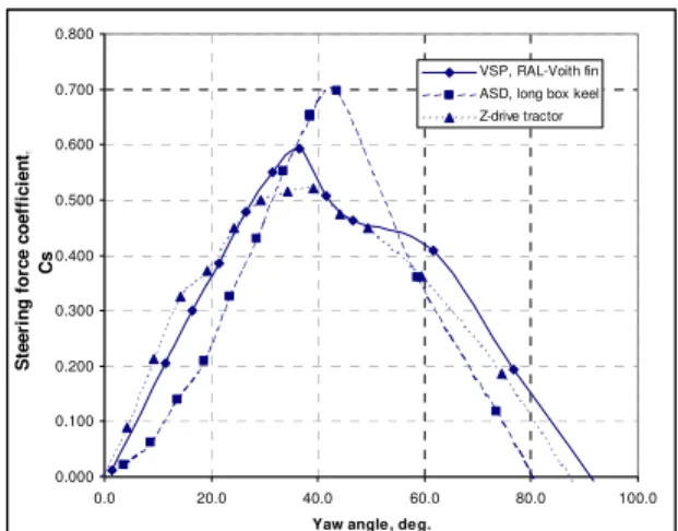
The performance parameters compared were steering force coefficient against yaw angle, center of lateral resistance against yaw angle and braking force coefficient against steering force coefficient. These comparisons are shown in Figures 8 to 10.
Figure 8 shows side force coefficient plotted against yaw angle for the three hull forms used in the comparison. This graph presents the results in the same format as lift coefficient against angle of attack for an airfoil. Steering force is the force component generated by the tug normal to the direction of the undisturbed fluid motion. The graph shows that each hull type tested has similar characteristics, with an almost linear relationship between steering force and yaw angle, up to a point of stall, and then steering force decreases to zero at between 80 and 90 degrees angle of attack. It is noticeable that the maximum steering force coefficient and stall angle varied with the hull type. The highest steering force coefficient and highest stall angle occurred for the ASD tug, which did not have the airfoil shaped skeg. This hull however had the lowest steering force coefficients up to yaw angles of 30 degrees. Clearly the ASD tug is very effective at large angles of attack, but less so at smaller ones.
The VSP tug and the Z-drive tractor tug had similar steering force coefficients up to 25 degrees, but above this value the VSP tug had the highest steering coefficient. The Z-drive tractor tug shows a distinct inflection point at approximately 15 degrees of yaw, and this combined with the lower peak in the steering force coefficient suggest that the higher aspect ratio skeg is stalling earlier than the lower aspect ratio skeg used on the VSP tug. For all the hulls, the stall angle is very high relative to two-dimensional airfoils, which typically stall at between 12 and 15 degrees.
The graph of centre of lateral resistance against yaw angle is shown in Figure 9. There is a large difference in the character of this relationship between the hulls with the fin style
Figure 8, Steering force coefficient against yaw angle, 6 knots 0.000 0.100 0.200 0.300 0.400 0.500 0.600 0.700 0.800 0.0 20.0 40.0 60.0 80.0 100.0
Yaw angle, deg.
S teer in g f o rce co ef fi ci ent , Cs VSP, RAL-Voith fin ASD, long box keel Z-drive tractor 0.000 0.050 0.100 0.150 0.200 0.250 0.300 0.350 0.400 0.450 0.500 0.0 10.0 20.0 30.0 40.0 50.0 60.0
Yaw angle, deg.
C lr ( as f ract ion of Lw l) VSP, RAL-Voith fin ASD, long box keel Z-drive tractor
Figure 9, Centre of lateral resistance against yaw angle -1.200 -1.000 -0.800 -0.600 -0.400 -0.200 0.000 -0.400 -0.200 0.000 0.200 0.400 0.600 0.800 Cs Cb VSP, RAL-Voith fin ASD, long box keel Z-drive tractor
Figure 10, Braking force coefficient against steering force coefficient
skegs and the hull with the box keel. For the hull with the box keel, the location of the center of lateral resistance only starts to stabilize at yaw angles over 40 degrees. The VSP and the Z-drive tractor hulls show very similar characteristics, with the center of lateral resistance remaining almost constant over yaw angles between 15and 30 degrees. Operational experience however suggests that ASD tugs are no more directionally unstable than VSP tugs.
For an escort tug, the total force acting on the tanker and how it is resolved into steering and braking force components is important, since the relative magnitudes of the forces effect the tanker’s trajectory. For the hull only data, non-dimensional braking force can be plotted against non-dimensional steering force, and the result is a polar plot, where the distance from the origin to the point on the curve is the total force generated by the hull. This is shown in Figure 10 for the three hull forms tested. This figure shows that the highest steering force was generated by the ASD tug, but that the corresponding braking force was also higher. The ASD tug also generated the lowest braking force at zero steering force (occurring at high yaw angles). This figure shows that the ASD tug had the lowest resistance. The large guard plates for the VSP and Z-drive tractor tugs is a disadvantage when the yaw angle is zero, due to the additional drag.
Combined Hull and Propulsion System Forces
The discussion above has only been concerned with the hydrodynamic forces generated by the hull, held at an angle of attack to the flow. Whilst it is useful for comparing different designs, it is not a realistic situation since the tug requires a propulsion system to hold this equilibrium position, and the forces generated by the propulsion system affect the steering and braking forces. This was the reason that experiments were also carried out with the propulsion system operating. Since maximum steering force and maximum braking force are the most important condition, all comparisons of hulls with working propulsion systems have been made for a ship speed of 10 knots.
Two variables have a major influence on the maximum force that can be generated by any particular hull form. One is the location of the towing staple (measured from the forward end of the waterline) and the other is the delivered power to the propellers. In practice, the designer may not have much flexibility in the selection of the propulsion machinery and its
limiting power. As a result, it is easier to fine-tune the staple location, although there is sometimes limited flexibility in this option as well due to layout and weight distribution considerations. For the size of tugs discussed in this paper, 3500 kW per shaft is a typical power.
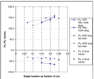
Figure 11 shows the effect of staple location on steering force for 35 degrees of yaw at 10 knots for each of the three concepts. This figure shows that all three designs are capable of providing 150 tonnes of steering force, but the staple location at which this occurs in each hull is different. -100.0 -50.0 0.0 50.0 100.0 150.0 200.0 0 0.05 0.1 0.15 0.2 0.25 0.3
Staple location as fraction of Lwl
Fs, F b, t onnes Fs, VSP, RAL-Voith skeg FB, RAL-Voith skeg Fs, ASD long box keel Fb, ASD long box keel Fs, Z-drive tractor Fb, Z-drive tractor
Figure 11, High steering force condition, effect of staple location on steering and braking forces, 10 knots
A critical factor to consider in the placement of the towing staple is the location of the center of lateral resistance. To ensure a “fail-safe” operating mode should the propulsion system on the tug fail, it is essential to position the towing staple a short distance ahead of the center of lateral resistance. Without this feature, a propulsion failure on the tug could result in a catastrophic combination of rapid yawing and rolling.
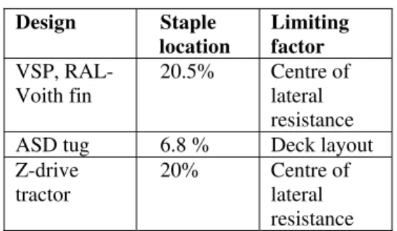
For three of the designs considered in this study, the limiting staple positions are given in Table 2 as percentages of the waterline length, from the forward end of the waterline, together with the limiting factor. For each of these conditions, the effect of speed on the results is shown in Figures 12 and 13, for high steering force and high braking force cases respectively.
Design Staple location Limiting factor VSP, RAL-Voith fin 20.5% Centre of lateral resistance ASD tug 6.8 % Deck layout Z-drive
tractor
20% Centre of
lateral resistance Table 2, Staple locations used for each design alternative when comparing the effect of speed on steering and braking forces
Figure 12, High steering force condition, effect of speed on steering and braking forces
Figure 13, High braking force condition, effect of speed on steering and braking force
Figure 12 shows that all three designs have very similar steering force values up to 8 knots, but at 10 knots, the VSP tug has the highest value, followed by the z-drive tractor and then the ASD tug. The braking forces are split by design throughout the speed range, with the VSP tug having the lowest values throughout the speed range, followed by the z-drive tractor and then the ASD tug.
For the high braking force condition, Figure 13, the z-drive tractor tug has the largest braking force, with the other two designs having very similar values at speeds of 8 knots and higher, but with the ASD tug having slightly larger values at 4 and 6 knots.
-250 -200 -150 -100 -50 0 50 0 2 4 6 8 10 Speed, knots
It is likely that the superior performance of the z-drive tractor tug is due to two factors. Relative to the ASD tug, the z-drives are in a more exposed location and the hull will have hardly any sheltering effect. Flow into the propellers will be almost the same as the free-stream flow. Compared to the VSP tug, the momentum of the flow in the propeller race will be higher, due to the higher rotational speed and smaller area affected by the propellers. As a result, when the wash from the propeller is directed across the free stream flow, a higher force will be generated for the same ship speed. These two factors combine to result in the higher braking force, with relatively little difference between the corresponding steering force values. The staple placement on the ASD tug could easily be altered with some revisions to the General Arrangement of the concept design used in this case. With a further aft position of the staple it is likely that the steering force performance would improve appreciably.
IMPACT OF HYDRODYNAMIC FORCES ON ESCORT TUG DESIGN
The design of an effective escort tug demands a very clear understanding of both the nature of tanker escort work and the many design variables which interact to establish the safe limits of escort tug operation. The most critical elements in an escort tug are size, stability, and power. The steering and braking forces developed are directly related to the projected underwater lateral area of the hull and appendages. The tug must also have installed power commensurate with the required bollard pull for handling large ships at slow speeds, and
For ce , t onne s VSP Fs VSP Fb ASD Fs ASD Fb Z-drive tractor Fs Z-drive tractor Fb -100 -50 0 50 100 150 200 0 2 4 6 8 10 Speed, knots Fo rce, t o n n e s VSP Fs VSP Fb ASD Fs ASD Fb Z-drive tractor Fs Z-drive tractor Fb
perhaps most critically must have a stability characteristic that ensures safe operations at all conceivable operating conditions.
Two other variables which are important in generating the maximum steering force for an escort tug, are the delivered power to the propellers and the fore and aft location of the towing staple. In general, for maximum steering force, the towing staple should be located as far away from the end of the waterline as possible, but under no conditions can it be further away than the center of lateral resistance. When the staple reaches this point, in principle the propulsion system is not required to generate any yaw moment, and all the propulsion force can be directed along the centerline of the hull. The center of lateral resistance is critically important as a fail-safe limit for the tug. In the event of a tug engine failure, with the staple between the center of lateral resistance and the end of the waterline, the hull will automatically yaw under influence of the towline tension to take up a dynamically stable position behind the tanker.
Increasing the level of delivered power to the propellers also increases the steering and braking forces. Careful selection of the power and staple location is required to ensure that the inherent hydrodynamic properties of the hull are used to full advantage. A hull that has the capability to generate high steering force is wasted if the towing staple is not in its optimum location, and if it lacks commensurate high angle stability.
Operating practice has shown that the quickest way to bring a tanker under control provided there is room, is to turn the tanker as quickly as possible. Under these conditions, maximizing steering force is an important design feature, and so the long box keel is a sound choice from a hydrodynamic point of view.
Based on the analysis of the hydrodynamic forces, it is possible to design an efficient escort tug based on any of the three propulsion configurations tested that will achieve a specified maximum steering force within closely similar overall dimensions and displacement of tug. Given this observation, other factors can then be considered in the design of a successful escort tug. These include maximum achievable bollard pull, maximum free-running speed, overall design flexibility, costs (initial and operating), maximum operating draft, reliability, damage tolerance, transient behavior of the main machinery and propulsion system, and perhaps most importantly the impact of propulsion machinery selection and placement
on overall tug flexibility and utility in performing a broad range of anticipated towing-related activities.
RECOMMENDATIONS FOR
FURTHER RESEARCH
There has been very little systematic research into the hydrodynamic performance of escort tugs. One reason has been the cost of the required experiment program relative to the typical cost of an overall project. There is usually little opportunity for specific, project based experiment programs within a typical design and construction budget. It is hoped that the work described in this project will make a substantial contribution to the amount of information available to escort tug designers and owners.
For reasons of cost, the model z-drives at IOT were not fitted with thrust-augmenting nozzles. For determining the total hydrodynamic force, this omission is probably not important, since total thrust can be simulated, but at incorrectly scaled propeller rotation rates. In practice, a nozzle would be fitted to the z-drives. The classical duct shapes of 19A and 37 were both developed by MARIN.
Brandner and Rennilson (1998) chose the 19A nozzle for their investigation of z-drive performance in oblique flow, which showed the variation of thruster force with flow angle and yaw angle. Selecting the 19A nozzle on a z-drive was logical since the loss of astern performance for the 19A relative to 37 is not significant, because the thruster is rotated to change the direction of the force.
However, the best duct shape for a propeller operating with non-zero inflow angles has not yet been established. Cavitation and vibration characteristics of different duct shapes, as well as the total force developed are potential areas for additional research.
The approach taken to date in modeling escort tug performance has focused on predicting a specified steering or braking force. The captive model procedure does not give any indication of the directional stability of the tug. It has been observed in radio controlled model experiments and full-scale trials that when high braking forces are being developed at high speeds, the tug does not take up a constant position relative to the tanker. There is instead a tendency for the tug to oscillate from side to side, relative to the track of the tanker. The amplitude of the period
oscillation, and the roll angles encountered during the transitions can be important in determining the safe limits of the maneuver.
These problems cannot easily be addressed by the semi-captive method and are best addressed with a radio controlled tethered model at later stages in the design process. The semi-captive approach used here is designed to locate the centre of lateral resistance, the optimum position for the towing staple and the minimum required power. Dynamic stability is better addressed after these variables have been fixed.
Another factor that should be given some consideration is scaling of the results of the model experiments. Normal practice in ship model testing is to separate the skin friction resistance from the residuary resistance. Skin friction resistance coefficient is scaled using the ITTC 1957 (or ITTC 1978) methods, and the calculated residuary resistance coefficient is assumed to be the same between model and ship. The assumption in the ITTC methods is that the flow around the ship remains attached to the hull, and only separates at the stern. For an escort tug, this assumption is no longer true. All the forces and force coefficients presented in this paper have been on the basis of pure linear scaling of the forces, with no corrections for viscous flow. Some preliminary work for another escort model test project carried out at IOT has indicated good comparison between model results scaled in this manner and full scale trials, but further study should be carried out to determine appropriate scaling practices for escort tugs.
CONCLUSIONS
The typical performance specification for an escort tug is a minimum required steering force at 10 knots. This must be obtained in a hydrodynamic condition, which is normally considered to be ‘off-design’, with a high yaw angle for the hull and an inflow angle for the propulsion system. This results in very disturbed flow, with high levels of separation. Model experiments are a very practical method of predicting the resulting forces given this complex flow situation.
A semi-captive method, which holds the tug at a fixed yaw angle, but allows freedom to roll, is the preferred test method at the early stages of design assessment. The optimum
location of the towing staple and the level of delivered power can be determined by interpolation from within a set of data points.
The hydrodynamic forces generated by the hull alone are a useful indicator of the tug’s performance and can be used as an initial measure of comparison. The addition of a working propulsion system reduces the differences between the three hull and appendage concepts discussed in this paper, and this is probably due to interference effects between the flow around the hull and the flow through the propulsion system.
For a propulsion system working in off-design conditions, there can be dramatic differences in the level of force produced at different thruster orientations relative to the flow. For maximum steering force, there appears to be little effect relative to normal open water performance, but for the tug generating maximum braking force, the force from the propulsion system can be almost twice the force obtained in the bollard condition.
Based on the results of the hull forms tested for this project, an ASD design has the best potential for generating steering force, but the staple location and level of delivered power must be selected to ensure that the specified steering force is achieved. In conjunction with this indirect steering force capacity, the Z-drive propulsion also offers a higher bollard pull for the same installed power.
There seems to be no significant difference between the hydrodynamic forces of the combined hull and propulsion systems tested for the three tug concepts tested as part of this project. A specified steering force (for example, 150 tonnes) can be achieved by all of the concepts, provided that the hull is designed to provide the appropriate level of stability. As a result, the designer is free to select the propulsion system that offers the best overall combination of vessel performance and layout advantages, in the most cost-effective manner.
ACKNOWLEDGEMENTS
The authors would like to thank Mr. C. J. Amundsen of Carl Amundsen and Associates, Dr. J-E Bartels and Mr. H. Gross of Voith– Schiffstechnik GmbH for their invaluable assistance during the initial experiment programs described in this report and all the other staff at
Robert Allan Ltd. and IOT who contributed to this project.
REFERENCES
Allan, R. ‘Developments in Escort Tug Technology’, 15th International Tug and Salvage Conference, Paper 4, Day 3, 1998.
Allan, R., Bartells, J-E., and Molyneux, D. ‘The Development of a New Generation of High Performance Escort Tugs’, Proceedings, International Towage and Salvage Conference, Jersey, May 2000.
Allan, R. ‘The Evolution of Escort Tug Technology: Fulfilling a Promise’, Trans. SNAME, Vol. 108, 2000, pp. 99-122.
Brandner, P. and Renilson, M. ‘Interaction Between Two Closely Spaced Azimuthing Thrusters’, Journal of Ship Research, Vol. 42, No. 1, March 1998, pp. 15-32.
Brooks, G. and Slough, S. W. ‘The Utilization of Escort Tugs in Restricted Waters’, Port
Technology International, Vol. 9, 2001, pp.
221-228.
Hutchison, B., Gray, D. and Jagannathan S. ‘New Insights into Voith Schneider Tractor Tug Capability’, Marine Technology, Vol. 30, No. 4, 1993, pp. 233-242
Scalzo, S. ‘Experience with the Design and Operation of Escort Tugs, The Way Ahead’, International Conference on Escort Tugs, Royal Institution of Naval Architects, October 1993