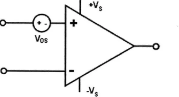
AC coupled ripple reduction method for chopper-stabilized amplifiers
Texte intégral
Figure


Documents relatifs
Results derived from images obtained in a controlled laboratory water tank environment with different turbidity conditions and images from tests using the proposed method at sea
L’archive ouverte pluridisciplinaire HAL, est destinée au dépôt et à la diffusion de documents scientifiques de niveau recherche, publiés ou non, émanant des
Therefore the chosen strategy here is to maximally relax the realization of the analog part. To do that, the presented methods start from the knowledge of the frequency responses of
rétinite nécrosante (patients sous traitement immunosuppresseur), Varicelle, Zona
2 for λ=1 : (a) depicts the response for a steady illumination, the posterior ratio u(t) and the calcium concentration both converge to the same steady state, with a time
For population-level analyses and for model fitting, the relative response amplitude (RA n ) was calculated by divid- ing the amplitude of the N-wave obtained at the nth
Observer and first-order low-pass filter based attitude estimation for rigid bodies subject to external acceleration.. Conference on Decision and Control, Dec 2019,
SNR comparison between DW T non-linear denoising and classical low-pass linear filtering for a an ECG -type reference signal, as a function of the input SNR in.. The cut off


