HAL Id: hal-01845308
https://hal.archives-ouvertes.fr/hal-01845308
Submitted on 20 Jul 2018HAL is a multi-disciplinary open access archive for the deposit and dissemination of sci-entific research documents, whether they are pub-lished or not. The documents may come from teaching and research institutions in France or abroad, or from public or private research centers.
L’archive ouverte pluridisciplinaire HAL, est destinée au dépôt et à la diffusion de documents scientifiques de niveau recherche, publiés ou non, émanant des établissements d’enseignement et de recherche français ou étrangers, des laboratoires publics ou privés.
Al-O-N AND Al-O-B-N THIN FILMS APPLIED ON
Si-O-C FIBERS
Adrien Delcamp, Laurence Maillé, S Martin, R. Pailler, Alain Guette
To cite this version:
Adrien Delcamp, Laurence Maillé, S Martin, R. Pailler, Alain Guette. Al-O-N AND Al-O-B-N THIN FILMS APPLIED ON Si-O-C FIBERS. Composites Science and Technology, Elsevier, 2010, 70 (4), pp.622 - 626. �10.1016/j.compscitech.2009.12.012�. �hal-01845308�
Al-O-N AND Al-O-B-N THIN FILMS
APPLIED ON Si-O-C FIBERS
A. Delcamp, L. Maillé*, S. Saint Martin, R. Pailler, A. Guette
University of Bordeaux 1, Laboratoire des Composites ThermoStructuraux, 3 allée de La Boetie, 33600 Pessac, France
Abstract
Protective coatings (Al-O-N and Al-O-B-N) on Si-O-C fibers (Tyranno ZMI) were applied in order to enhance oxidation resistance under severe thermo-mechanical conditions in the 400-600°C temperature range. The coating process consisted in three steps: (i) the transformation of the Si-O-C fiber surface into microporous carbon; (ii) the impregnation of these carbon microporous layers by an aluminium trichloride (AlCl3)
solution and then, (iii) a final heat-treatment under ammonia. Processing parameters were studied in order to select the best conditions. Using these conditions, obtained results have shown that coatings were present around each fiber, with a controlled thickness, and that the mechanical properties of the fibers were preserved. Although, these coatings did not entirely stop the oxygen ingress, it has been shown that they strongly reduced the oxidation of the fiber.
Keywords
A. Coating, A. Ceramic-matrix composites, B. Mechanical properties, Oxidation.
1. Introduction
New environmental rules as well as economical competition have constrained the aeronautic industry to develop new products with low structural weight and ceramized
engines in order to reduce NOx and CO2 emissions. This is the result of a better combustion
and enables also a reduction of aircraft noise.
In order to reach these objectives ceramic matrix composites (CMC) have been selected since they display excellent thermo-mechanical properties as well as low densities [1]. The aim of the present study was focused on developing low cost raw materials and processes in order to be competitive on the civil aeronautic market. Low cost ceramic fibers such as Tyranno ZMI fibers were therefore selected [2]. When used in an oxidizing environment at elevated temperature, it has been shown that the use of a self healing matrix usually provides an accurate protection of the CMCs against oxidation [3]. However, when moderate temperatures are considered, self healing matrices have proved to be not so efficient. Hence, when CMCs exhibit matrix cracks, these cracks are not entirely healed because of the low rate of formation of the oxide. Further oxygen diffuses into the fibers, leading therefore to a catastrophic failure of the CMC [4]. In order to prevent any
propagation of the oxygen up to the fibers, and therefore to enhance the lifetime of these materials, it has been decided to set up a protective oxidation barrier on the surface of the Si-O-C fibers. This layer should posses all the following distinct features: to provide an individual and uniform coating around the fibers, while avoiding bonding between them; to prevent any oxygen diffusion to the fibers; to be stable during the processing of the matrix and of the interphase; to present a good adhesion with both the fibers and the interphase; and to preserve the mechanical properties of the fibers.
Different materials may be considered regarding these expected properties: refractory oxides such as ZrO2 or Al2O3 [5-6]; silicon based ceramics such as Si-B-C-N, Si-C-N [7-8]
or Si-Al-C-N [9-11], monazite [12-15], BN [16-21] and LaAlOx [22-26].
Two new materials were selected for the present work: Al-O-N and Al-O-B-N [27-30]. As a matter of fact, the aluminium as an element exhibits a low density as well as a stable oxide (Al2O3). Besides, most nitrides have attractive refractory properties. Boron was also
selected as an adequate element because of an important property of all boron containing species which is to form fluid oxide phases (B2O3) over a broad temperature range (600–
1200°C) in an oxidizing atmosphere. The Al-O-N-B material could thus be used to design self-healing composites with improved lifetimes. It bases on the in-situ formation of the fluid oxide, which fills the matrix cracks and slows down the in-depth diffusion of oxygen [3;31].
2. Experimental procedure
2.1. Thin coatings deposition
As already mentioned, Tyranno ZMI Si-O-C fibers (from UBE Industry, Japan), were used for this study. The microstructure of this first generation of Si-O-C fibers is composed of -SiC crystallites (2nm), free carbon and a Si-O-C phase resulting from the precursor reticulation step [32]. The chemical composition of these fibers (Si 37.7 at.%, C 53.4 at.%, O 8.8 at.% and Zr 0.1 at.%) has been determined using an electron probe microanalyser (SX 100 from CAMECA). The average fibre diameter is 13µm.
In order to promote an adequate adhesion between the Al-O-N or Al-O-N-B thin coatings and the fiber surface, microporous carbon layers with a controlled thickness were first produced, using a thermochemical treatment around 600°C with chlorine gas [33]. This specific treatment leads to an extraction of Si from SiC by chlorine at the fiber surface, according to the following reaction 1 [34]: SiC(s)+2 Cl2(g) = SiCl4(g)+C(s). The microporous
carbon thus obtained was found to possess a specific surface area, calculated using the Brunauer-Emmet-Teller equation, of 994m2/g. Most of the pores size (> 91%) are smaller than 2nm and the pore volume measures 0.45cm3/g (these values were calculated using the semi-empirical Horvath and Kawazoe approach). After this heat treatment, fibers were impregnated with an anhydrous aluminium trichloride (AlCl3) solution.
Only one impregnation was performed during 15 minutes, at ambient temperature, using a batch process. The samples were then heated up to about 120°C in order to evaporate the solvent, and a thermal treatment in an ammonia atmosphere during 60 minutes, at a constant flow rate of 20 sccm and at various temperatures (900, 950 and 1000°C), was finally performed.
In the case of the Al-O-B-N thin coatings, the fiber preforms were impregnated with boron acid prior to the impregnation with an aluminium trichloride solution. A heat treatment at 1150°C during one hour was then performed under an ammonia flow.
Three different types of composite materials were produced and tested: composites C1 only made with a pyrocarbon interface and a SiC matrix, considered as the reference material; composites C2 made with Al-O-N thin coatings and a SiC matrix; and composites C3 made with a pyrocarbon interface, an Al-O-N thin coating and a SiC matrix.
2.2. Thin coatings characterization
Both structural, chemical and mechanical characterizations were performed for each kind of coating.
The cross-section morphology was investigated with the aid of a high resolution Scanning Electron Microscopy (SEM, Hitachi S4500). Coating thicknesses as well as the quality of their adhesion to the fibers were studied by the observation of the fracture surfaces. Microstructural characterizations of the various coatings were performed with a Philips CM30ST (LaB6, 300kV) Transmission Electron Microscope (TEM). The chemical
composition and thicknesses of the coatings were evaluated using an Auger Electron Spectroscopy (VG Microlab 310 F) coupled with an argon sputter device. The analysis of the atomic content of each element was determined in the depth profile mode.
Room temperature fiber strength was determined by tensile tests performed on single fibers according to a procedure describe in [35]. These tests were performed on twenty fibers for
each sample, with a gauge length of twenty five millimetres. Each fiber extracted from a tow was fixed on paper frame holders using a hard acrylic resin. Ultimate tensile strength (r, in GPa), strain to rupture (r, in %) and Young’s modulus (E, in GPa) of the Si-O-C
fibers were derived from these tests. Mechanical tests on single ply (2D fiber weaves) with a SiC matrix were also performed.
Static oxidation tests were performed at 600 °C in air during 7000 hours. Silica thicknesses developed at the surface of the fibers were determined by SEM after a few weeks.
3. Results and discussion
Various processing parameters related to the impregnation and the nitridation have been studied.
3.1. The impregnation process
As mentioned before, aluminium compounds were deposited at the fiber surface through the impregnation by an aluminium trichloride solution (AlCl3) of microporous carbon first
created at the ZMI fiber surface by chlorination [27-28;36-37]. In this respect, in two fluids were tried to solve the AlCl3 powder, namely water and ether.
Although water proved to be a good solvent for hydrated AlCl3 powder, this solution yet
caused an important introduction of oxygen into the coating. Conversely, ether also proved to be a good solvent when using anhydrous AlCl3 powder, and consequently forms a
coating with a lower oxygen content. Ether was therefore preferred to impregnate the aluminium trichloride solution.
In a first attempt to impregnate a maximum of aluminium compounds into the microporous carbon, a saturated aluminium trichloride solution was realised. Yet, the high viscosity of this solution did not easily allow the impregnation of the fiber preforms by the aluminium compounds, as illustrated by the high resolution SEM image exhibited in figure 1. This which shows that thin coatings at the fiber surface were not homogeneous, with an excess
of matter deposited at the fiber surface. It was therefore then decided to use only thin coatings requiring a lower concentration of aluminium trichloride solution. As expected, a homogeneous microstructure could thus be obtained (figure 2 a) in which no bridge between Si-O-C fibers could be evidenced (figure 2 b). These amorphous coatings, which formed an individual and uniform coverage around each fiber, could thus be expected to efficiently protect the fiber surfaces.
3.2. The nitridation process
Nitridations were performed on samples previously impregnated with AlCl3 solutions at
900°C following the method described by L. Chen et al. [27;36-37], and then extended at 950°C and 1000°C.
The samples thus obtained were also analysed by Auger electron spectroscopy. Results, shown in figure 3, confirm that the impregnation of the aluminium compounds into the microporous carbon network was quite successful. However, the chemical compositions presented in tables 1 and 2 reveal that although all silicon compounds should have been consumed (after equation 1), it was yet possible to observe the presence of this element but in low amounts (figure 3).
Variations in the concentration of the chemical elements (Al, N, O, B and C) present in the coatings were observed according to the nitridation temperature. Besides, these Auger Electron Spectroscopy analyses have also shown that the thickness of the nitrated coatings tend to decrease as the temperature of the nitridation process was increased (figure 3). This last phenomenon can be explained by the reaction occuring between ammonia and carbon which leads to the formation of HCN and to a carbon depletion [38]. A densification of Al-O-N-B and Al-O-N coatings and therefore a decrease of their thickness, were thus
observed after using higher nitridation temperatures. In addition to their densification and concomitant carbon consumption, it has been evidenced that, in the case of Al-O-N thin films, the aluminium and oxygen content increased with the temperature of nitridation, as
presented in table 1. These last observations may be explained by a de-mixing process in gradually taking place in the coating as the nitridation temperature was increased, leading to the formation of Al2O3 while liberating nitrogen. Conversely, in the case of the
Al-O-N-B coatings, such phenomena were not observed (table 2). Finally, high resolution TEM showed that both thin films were homogeneous, amorphous (no ring patterns of selected-area electron-diffraction were observed) and adhere to the fibers.
3.3. Mechanical properties and oxidation behaviour
Some mechanical properties (Young’s modulus, stress and strain to rupture) of single fibers coated with Al-O-N and Al-O-N-B thin films were studied. Results are reported in tables 1 and 2.
Whereas heat treatments performed up to 950°C did not degrade the mechanical properties of the various coated ZMI fibers, both stress and strain to rupture of the fibers coated by Al-O-N and nitrated at 1000°C were found to decrease. This phenomenon can be explained by a reaction between the ammonia and the free carbon contents of the fibre as well as by the aforementioned a de-mixing process occuring in Al-O-N when the temperature of the nitridation process is increased.
On the other hand, stress and strain to rupture of Al-O-N-B coated fibers, nitrated at 1000°C, proved to be stable. Indeed, at this temperature the ammonia reacts preferentially with boron oxide to form boron nitride and water. This formation of boron nitride, which acts as an interphase (confirmed by TEM in figure 4), permits to preserve the mechanical properties of the fibers. Indeed, TEM analyses showed that these Al-O-N-B thin coatings were amorphous, and mainly composed of aluminium, boron, nitrogen and boron
compounds with few nano-crystals of BN and Al4B2O9.
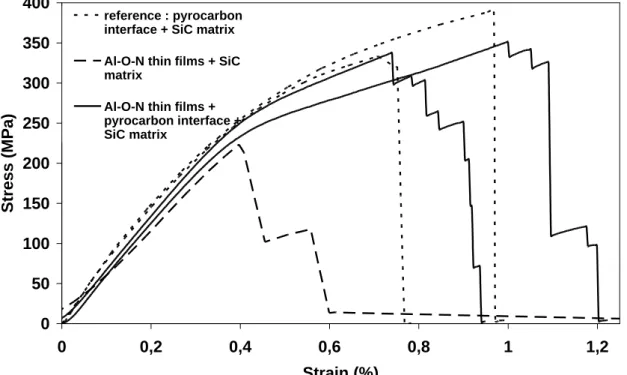
Results of the mechanical tests performed on different single ply composites made of treated ZMI fiber in a CVI-SiC matrix are presented in figure 5.
Composites C2 did not present acceptable mechanical properties. Indeed, the observed very limited non linear domains tend to evidence an inherent brittleness (with strains to rupture less than 0.4%). These results can be attributed to a noticeable degradation of the fiber as compared to the reference material C1. Conversely, samples C3 with both an Al-O-N coating and a pyrocarbon interface did not reveal any degradation of the mechanical properties, as compared to the reference material. It may thus be concluded that the pyrocarbon interphase is still necessary to obtain an overall non linear/non brittle behaviour.
Results of static oxidation tests are presented in figure 6. The usual passive oxidation of SiC based fibers leads to the formation of a silica layer. The presence of N or Al-O-N-B coatings has resulted in an important reduction of the silica scale. However, neither Al-O-N nor Al-O-N-B coatings were able to totally prevent the oxygen ingress towards the fiber surface.
4. Conclusion
Two different protective coatings, Al-O-N and Al-O-N-B respectively, have been applied on Si-O-C fibers in order to enhance their oxidation resistance under severe thermo-mechanical conditions. Aluminium and nitrogen were introduced into a microporous carbon surface by impregnation of an aluminium trichloride solution, followed by a heat treatment and by anitridation of these thin films (consisting of a thermal treatment in an ammonia atmosphere). Auger spectroscopy and SEM associated to an EDS detector have confirmed the effectiveness of the presence of Al-O-N and Al-O-N-B thin coatings at all the fiber surfaces. These coatings were sufficiently homogeneously distributed to allow the absence of bridging between the fibers. The mechanical compatibility of these applied coatings have been assessed with the help of tensile tests performed on single fibre as well
as on composites produced from a 2D fabric containing the fibre with the different coatings mentioned above after impregnation with SiC matrix.
Obtained results have shown that, in both cases, the coatings preserve the mechanical integrity of the fibers, if an additional pyrocarbon interphase is present. Oxidation
experiments at 600°C showed that the different coatings considerably decrease oxide scale formation on the fibers which will lead to an increase of the lifetime of the ceramic matrix composites.
Acknowledgments
The authors acknowledge the financial support of ADEME for this work and M. Lahaye and P. Weisbecker for Auger electron spectroscopy and Cross Polishing respectively.
References
1. Naslain R. Introduction aux matériaux composites, 2-Matrices métalliques et céramiques, édition CNRS, Institut des matériaux composites. 1979, p. 30-31. 2. Shibuya M, Yamaoka H, Kumagawa K, Yamamura T. 9th Cimtec World Forum on
New Materials - Symposium V - Advanced structural fiber composites - Florence, Italy, Vincenzini P (Editor) - Techna Srl. 1999, p. 63-70.
3. Naslain R, Guette A, Rebillat F, Pailler R, Langlais F, Bourrat X. J. Solid State Chem., 2004;177: 449-456.
4. Filipuzzi L. Oxydation des composites SiC/SiC et de leurs constituents : approche expérimentale, modélisation et influence sur le comportement mécanique. PhD Thesis, University of Bordeaux 1, Bordeaux, France, 1991.
5. Baklanova NI, Zima TM, Naimushina TM, Kosheev SV. J. Euro. Ceram. Soc. 2004;24:3139-3148.
6. Baklanova NI, Titov AT, Boronin AI, Kosheev SV. J. Euro. Ceram. Soc. 2006;26:1725-1736.
7. Kern F, Gadow R. Surf. Coat. Technol. 2002;151:418-423.
8. Kern F, Gadow R. 27th International Cocoa Beach Conference on Advanced Ceramics Composites, COCOA BEACH – FL, Book Series: Ceram. Eng. Sci. Proc.
2003;24:239-246.
9. Dhamne A, Xu WX, Fookes BG, Fan Y, Zhang L, Burton S, Hu J, Ford J, An L. J. Am. Ceram. Soc. 2005;88:2415-2419.
10. Wang Y, An L, Fan Y, Zhang L, Burton S, Gan Z. J. Am. Ceram. Soc. 2005;88:3075-3080.
11. Wang Y, Fei W, An L. J. Am. Ceram. Soc. 2006;89:1079-1082. 12. Hay RS, Boakye E, Petry MD. J. Euro. Ceram. Soc. 2000;20:589-597. 13. Boakye E, Mogilevsky P, Hay RS, Welter J, Kerans RJ. J. Am. Ceram. Soc.
2006;89:3481-3490.
14. Boakye E, Mogilevsky P, Parthasarathy TA. J. Am. Ceram. Soc. 2006;89:3475-3480. 15. Bansal NP, Wheeler DR, Chen YL. J. Adv. Mater. 2004;36:3-13.
16. Perez-Rigueiro J, Celemin JA, Herrero P. J. Am. Ceram. Soc. 1999;82:3494-3500. 17. Lii DF, Huang JL, Tsui LJ, Lee SM. Surf. Coat. Technol. 2002;150:269-276.
18. Shen L, Tan BJ, Willis WS, Galasso FS, Suib SL. J. Am. Ceram. Soc. 1994;77:1011-1016.
19. Lin HT, Becher PF. Mater. Sci. Eng. A.1997;231:143-150.
20. Le Gallet S, Rebillat F, Guette A, Bourrat X, Doux F. J. Mater. Sci. 2004;39:2089-2097.
23. Cinibulk MK. J. Europ. Ceram. Soc. 2000;20:569-582.
24. Wu YQ, Zhang YF, Huang XX, Guo JK. Ceram. Inter. 2001;27:903-906.
25. Saruhan B, Komarneni S, Abothu IR, Loong CK. J. Am. Ceram. Soc. 2000;83:3172-3178.
26. Schafer GW, Gadow R. Ceram. Eng. Sci. Proc. 1999;20:291-297. 27. Chen L, Gogotsi Y. J. Appl. Ceram. Technol. 2004;1 (1):68-75.
28. Gogotsi Y, Mcnallan M. US Patent n° WO 2005/092610 A1, 6 Oct. 2005. 29. Lin CY, Lu FH. J. Europ. Ceram. Soc. 2008;28 (3):691-698.
30. Hultman L. Vacuum.2000;57 (1):1-30.
31. Lamouroux F, Bertrand S, Pailler R, Naslain R, Cataldi M. Composites Sci. Technol. 1999;59:1073–1085.
32. Le Coustemer P, Monthioux M, Oberlin A. AMAC-CODEMAC Bordeaux-France, Naslain R, Lamalle J., Zulian J. (editors) 1990;43-53.
33. Mcnallan M, Ersoy D, Gogotsi Y. US Patent n° WO 01/16054 A2, 8 March 2001. 34. Chen L, Behlau G, Gogotsi Y, McNallan MJ. Ceram. Eng. Sci. Proc. 2003; 24
(3):57-62.
35. Delcamp A. Protection de fibres base SiC pour composites à matrice cérammique. PhD Thesis, University of Bordeaux 1, Bordeaux, France, 2008.
36. Chen L, He H, Gogotsi Y. J. Am. Ceram. Soc. 2003;86 (11):1830-1837. 37. Chen L. Carbothermal synthesis of coatings on SiC fibers. PhD Thesis, Drexel
University, Philadelphia, USA, 2004.
List of figure and table captions
Figure 1: High resolution SEM image of thin coatings at the fiber surface with a saturation
concentration of aluminium trichloride solution (4.3 M).
Figure 2: High resolution SEM images of thin coatings with a concentration of aluminium
trichloride solution equivalent to 1.8M a) at the fiber surface and b) on cross section.
Figure 3: Auger spectroscopy analyses of thin coatings after nitridation at a) 900°C, b)
950°C and c) 1000°C.
Figure 4: TEM images of Al-O-N-B thin coatings: a) Bright field image; b) High
resolution field.
Figure 5: Tensile stress-strain curve of a simple 2-D weave Si-O-C fiber reinforced SiC as
influenced by the Al-O-N thin coating with and without a pyrocarbone layer.
Figure 6: Silica thicknesses (x) created at 600 °C in air during forty weeks, on Tyranno
ZMI fiber without coating (a), with Al-O-N coating (b), with Al-O-N-B coating (c).
Table 1: Thicknesses and mechanical properties of fiber with Al-O-N thin coatings after
different nitridation temperatures.
d1:Thickness of Al-O-N or C coatings; : diameter of fibre; σr: stress at rupture; E: Young’s modulus; εr: strain to rupture
Table 2: Thicknesses and mechanical properties of fiber with Al-O-N-B thin coatings
after different nitridation temperatures.
d2:Thickness of Al-O-N or C coatings, diameter of fibre; σr: stress at rupture; E: Young’s modulus; εr: strain to rupture
Figure 1
Figure 3
a) 900°C 0 10 20 30 40 50 60 70 0 100 200 300Distance from the fiber surface (nm)
a to m ic p e rc e n t (% ) O C Si N Al b) 950°C 0 10 20 30 40 50 60 0 50 100 150
Distance from the fiber surface (nm)
a to m ic p e rc e n t (% ) O C Si N Al c)1000°C 0 10 20 30 40 50 60 0 50 100 150
Distance from the fiber surface (nm)
a to m ic p e rc e n t (% ) O C Si N Al
Figure 4
fiber
resin
a
Al-O-N-B thin film
d = 3.56 Å
d = 2.60 Å
bAl
4B
2O
9Al
4B
2O
9BN
d = 2.11
Å
Figure 5
0 50 100 150 200 250 300 350 400 0 0,2 0,4 0,6 0,8 1 1,2 Strain (%) Stre ss (MPa) reference : pyrocarbon interface + SiC matrix Al-O-N thin films + SiC matrixAl-O-N thin films + pyrocarbon interface + SiC matrix
Figure 6
0
20000
40000
60000
80000
100000
120000
140000
160000
0
100
200
300
treatment duration (days)
x
2(
n
m
²)
a )
b )
c )
Table 1
Fiber d1 Chemical composition (at.%) σr E εr (nm) (µm) C O Al N Si (GPa) (GPa) (%) without any treatment - 13.0 3.2 ± 0.7 210 ± 8 1.5 ± 0.3 with the carbon coating 560 ± 46 13.0 3.1 ± 0.3 162 ± 6 1.9 ± 0.3 With Al-O-N coating after 900°C nitridation treatment 246 ± 13 12.3 63 15 15 5 2 3.4 ± 0.4 178 ± 22 1.9 ± 0.3 With Al-O-N coating after 950°C nitridation treatment 129 ± 12 12.1 11 38 29 16 6 3.2 ± 0.4 184 ± 8 1.7 ± 0.2 With Al-O-N coating after 1000°C nitridation treatment 39 ± 15 11.9 10 47 30 9 4 2.5 ± 0.8 198 ± 16 1.3 ± 0.4Table 2
Fiber d2 Chemical composition (at.%) σr E εr (nm) (µm) C O Al N B (GPa) (GPa) (%) without any treatment - 13.0 3.2 ± 0.7 210 ± 8 1.5 ± 0.3 with the carboncoating 560 ± 46 12.3 3.1 ± 0.4 162 ± 6 1.9 ± 0.3 with Al-O-N-B coating after 1000°C nitridation treatment 180 ± 13 12.2 15 45 17 18 5 3.0 ± 0.4 205 ± 22 1.5 ± 0.2 with Al-O-N-B coating after 1050°C nitridation treatment 140 ± 16 12.1 15 25 17 25 18 3.0 ± 0.4 200 ± 21 1.5 ± 0.2 with Al-O-N-B coating after 1100°C nitridation treatment 70 ± 10 12.0 15 15 10 30 30 2.8 ± 0.5 185 ± 7 1.5 ± 0.3