HAL Id: hal-01761320
https://hal.archives-ouvertes.fr/hal-01761320
Submitted on 8 Apr 2018HAL is a multi-disciplinary open access archive for the deposit and dissemination of sci-entific research documents, whether they are pub-lished or not. The documents may come from teaching and research institutions in France or abroad, or from public or private research centers.
L’archive ouverte pluridisciplinaire HAL, est destinée au dépôt et à la diffusion de documents scientifiques de niveau recherche, publiés ou non, émanant des établissements d’enseignement et de recherche français ou étrangers, des laboratoires publics ou privés.
Thermal properties measurements of a silica/pyrocarbon
composite at the microscale
Indrayush De, Jean-Luc Battaglia, Gérard Vignoles
To cite this version:
Indrayush De, Jean-Luc Battaglia, Gérard Vignoles. Thermal properties measurements of a sil-ica/pyrocarbon composite at the microscale. Journal of Applied Physics, American Institute of Physics, 2016, 120 (24), pp.245101. �10.1063/1.4972974�. �hal-01761320�
Thermal properties measurements of a silica/pyrocarbon composite at
the microscale
Indrayush De
1, Jean-Luc Battaglia
1, Gérard L. Vignoles
21
I2M Laboratory, University of Bordeaux, UMR CNRS 5295, 351 Cours de la Libération, 33405 Talence Cedex, France
2
LCTS Laboratory, University of Bordeaux, UMR CNRS 5801, 3 Allée de la Boétie, 33600 Pessac, France
Abstract
Laminar pyrocarbons are used as interphases or matrices of carbon/carbon and ceramic-matrix composites in several high-temperature aerospace applications. Depending on their organization at the microscale, they can have a variety of mechanical and thermal properties. Hence, it is important to know, before thermal processing, the properties of these matrices at the micrometer scale in order to improve and control the composite behavior in a macroscopic scale. We use Scanning Thermal Microscopy (SThM) on a silica fiber / regenerative laminar pyrocarbon matrix composite to provide an insight into the effective thermal conductivity of pyrocarbon as well as the thermal contact resistance at the interface between fiber and matrix. The conductivity of pyrocarbon is discussed as a function of its nanostructural organization.
I Introduction
Carbon/carbon (C/C) composite materials are choice materials for use in extreme environments, such as space propulsion rocket nozzles, atmospheric re-entry thermal protection systems, aircraft brake discs, and Tokamak plasma-facing components1. In addition to carbon fibers, they contain interphases and matrices made of pyrolytic carbon, or pyrocarbon (PyC)2. This special type of carbon can be though of as a heavily faulted graphite. It is prepared via a gas-phase route, called Chemical Vapor Deposition (CVD) or Infiltration (CVI). It is therefore quite unavailable in bulk form. It has, depending on its processing parameters, a very versatile nanostructure3-5 and consequently, broadly varying mechanical and thermal properties, usually anisotropic to a more or less large extent6. Posterior heat treatments may further alter their structure and properties7. Hence, it is important to know the properties of these matrices at the micrometer scale in order to improve and control the composite behavior in a macroscopic scale. In this frame, a large variety of PyC samples have been prepared8. That represented in Fig. 1 consists of an as-deposited regenerative laminar (ReL) PyC9 deposit made on 5-µm radius glass fibers. The general orientation of the anisotropic texture is concentric around the fibers, as exhibited in Fig. 2, and results in orthotropic thermal properties of the matrix in the cylindrical coordinate frame following the fiber axis. This is due to the fact that the graphitic sheets exhibit strong thermal anisotropy. The thermal behavior of these non-homogeneous composites can be captured through characterization that will provide the thermal properties of the PyC. Previous thermoreflectance (TR) experiments10-12 have been performed to assess the anisotropic thermal diffusivity of the Smooth Laminar (SL) PyC and of the Rough Laminar (RL) PyC, either pristine or after different heat treatments. It was obtained that the in-plane thermal diffusivity (in orthoradial direction) for the as-prepared SL PyC matrix was 0.14 cm².s-1 while the ratio of the in-plane and out-of-plane thermal diffusivities was 7; the as-prepared RL exhibits higher figures (0.42 cm2.s-1 and 20, respectively), denoting a more graphitic and anisotropic structure. ReL PyC, which is a highly anisotropic form of PyC, differs from RL by a larger amount of defects13 and had not been
investigated so far. The TR method has in the current case some possible drawbacks: first, its spatial resolution is of the same size as the deposit thickness, a fact that could result in inaccuracies; second, this method requires a rather strong temperature increase on the heating area in order to increase the signal-to-noise ratio, therefore yielding an effective diffusivity characteristic at temperature markedly higher than the ambient and nonlinear effects. On the other hand, the thermal boundary resistance (TBR) at the interface between the fiber and the matrix has not been investigated so far. Since the thermal conductivity for both the silica fiber and the PyC along the radial axis is low, the TBR was not expected to be a key parameter on heat transfer. However, its quantitative identification from measurements at the microscale could bring complementary information regarding the chemical bonding and/or structural arrangement at the interface14.
In order (i) to overcome the drawbacks of the TR method, (ii) to provide thermal conductivity value for ReL PyC, and (iii) to measure as well the thermal boundary resistance at the interface between the PyC and the glass fiber, we have implemented the scanning thermal microscopy (SThM) experiment involving the 3ω mode15. The advantage of using SThM is that (i) the spatial resolution achieved is in the sub-micron scale and (ii) that high temperature differences are not involved, avoiding thus any risk of nonlinearity. In addition, SThM leads to absolute temperature measurements of the probe as well as to phase measurements when working under the 3 mode. Therefore, advanced inverse techniques can be implemented that can benefit from the frequency and spatial variations of both functions in order to investigate the thermal properties of the PyC and the TBR at the interface between the fiber and the matrix. In the present study the fiber is made of a single glass structure whose properties are available in literature16 ( k=1.4 W.m -1 .K-1,
r
= 2200kg.m-3, Cp=787 J.kg -1.K-1). The density and specific heat of ReL PyC have been also measured as13 = 2110 kg.m-3 and Cp = 748 J.K
-1
.kg-1 respectively.
Figure 1. Microscopic Image of the Composite Structure obtained using a Scanning Electron Microscope (SEM). Silica fibers (5 µm in radius) in grey color, surrounded by the PyC matrix in dark grey color, are
Figure 2. a) Image showing the silica fiber and the cylindrical arrangement of the graphitic sheets; b) SEM image at a higher resolution confirming the presence of a concentric arrangement of the anisotropic
texture, c) Dark field TEM image showing the anisotropic nature of the pyrocarbon, d) High-Resolution 002 Lattice Fringe TEM imaging of the pyrocarbon; the inset is a Selected Area Electron Diffraction Diagram illustrating the high anisotropy through the low value of the 002 diffraction arc opening angle.
II Scanning Thermal Microscopy in 3
mode - experiment
Scanning thermal microscopy is a well-established and almost ideal tool for investigating nanostructures like semiconductors and nano-electronic devices, due to its intrinsic sensitivity with respect to local material properties and to the thermal wave’s ability to propagate through the material with sub micrometer lateral resolution. Since its inception in 1986, based on the principle of Scanning Thermal Profile (STP)17, SThM has seen a lot of improvements and developments18-21 including the Wollaston probe and thermocouple probes. The employed SThM (Nanosurf Easyscan AFM) uses a 400 nm-thick silicon nitride (Si3N4) AFM probe provided by Kelvin Nanotechnology, on which is deposited a
palladium strip (Pd, 1.2 µm thick and 10 µm long) that plays both the roles of the heater and of the
a)
10 µm
b)
ReL
PyC
Silica
fiber
c)
d)
OA = 27°
thermometer. The SThM probe has a tip curvature radius of rs = 100 nm. The contact force between the
probe and the sample was chosen between 5 and 10 nN during our experiments and was accurately controlled during the probe motion using a feedback-closed loop on a piezo element, which ensures the displacement in the z direction with precise steps of 1 nm. The contact area between the probe and the surface is assumed to be a disk with radius r0. A periodic current
I =I0cos
( )
wt with angular frequencyw
=
2
p
f
passes through the strip with electrical resistance R0 at room temperature, generating Joule’seffect and, thus, being a heat source, dissipating the power
P 2
( )
w
=P0(
1+cos 2( )
w
t)
2 at a frequency of2w, where
P0=R0I0
2. The resulting temperature increase ΔT in the strip is composed of a continuous component (DC) and of a periodic one at 2ω, as
DT= DTDC+ DT2wcos 2
(
wt+f)
. This leads to changes of the strip electrical resistance asR=R0cos 1+
(
aRDT)
, wherea
R=1 R0dR dT is the thermal coefficient.The voltage drop between the two pads of the probe is therefore expressed according to , 2 and 3 . The third harmonic
U3w is related to the transient contribution of the temperature change to resistance as
DT2w=2U3w R0I0
a
R. In our configuration, R0=155 and I0=750 µA. The quantity DT2wmust be viewedas an average temperature value of the Pd wire since the change is expected to occur very close to the probe tip when it enters into contact with the investigated material surface. The harmonic contribution is measured using a differential stage coupled with a lock-in amplifier. The thermal coefficient of the Pd strip was calibrated by measuring the change in sensor resistance as a function of temperature and a value of
aR=
(
1.3±0.2)
´10-3K-1 was obtained. The contact between the probe and the surface involves a thermal boundary resistance that plays a very significant role on the measured temperature. This resistance involves at least three main contributions22, 23: (i) the solid-solid contact resistance, (ii) the heat diffusion through the gas surrounding the probe and the water meniscus that forms inevitably at the probe tip and (iii) the change in the temperature gradient within the Pd strip between the out-of-contact mode (used to evaluate the probe thermal impedance) and when the probe comes into contact with the surface. In the present study, although working under argon flow (after a preliminary air removal from primary vacuum), the diffusion through the gas and the water meniscus may still be present even if its contribution is bounded below. Moreover, for silicon nitride probes, the increase in the contact area can also be explained by the flattening of the tip apex when in contact with the sample. As we showed in a previous study18, the thermal contact resistance integrates all the physical phenomena listed above and that occur to form the thermal contact resistance Rc at the interface between the probe and the surface. On the other
hand, we observed18 that, in this experimental condition, the contact resistance as well as the radius r0 of
the heated area did not vary significantly when the thermal conductivity of the sample varied from 0.2 to 40 W.m-1.K-1. This observation was made considering the probe was motionless and the roughness of all samples was less than 10 nm. Finally, it was also observed18 that the sensitivity to the thermal conductivity variation started to vanish above 25 W.m-1.K-1. This is obviously related to the very small contact area since the smaller this area, the lower is the sensitivity to thermal conductivity change for high conductive samples. Finally, it was observed that the measured phase did not vary significantly with respect to the measurement error whatever the thermal conductivity of the material.
III Scanning Thermal Microscopy in 3
mode – heat transfer model
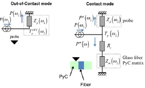
Figure 3. Heat transfer model for the out-of-contact operation mode and the contact mode (considering the probe in contact either with the glass fiber or the PyC matrix). Tp
OFC
is the out-of-contact probe temperature that is used to identify the probe thermal impedance Zp(). The current generator represents
the heat source, localized within the Pd strip of the probe.
The heat transfer in the probe and the investigated material, in both the out-of-contact and contact modes, is described in Fig. 3, using the thermal impedances formalism24. This contact mode configuration assumed that the probe was located on either the fiber or the matrix and was only sensitive to the thermal properties of the contacting material. In other words, this configuration suggests that the probe was put in static contact on both materials far away enough from the interface. Denoting
w
2=2w
, the average temperatureTp
( )
w2 of the Pd strip in the contact mode is related to the total heat flux P( )
w2 generatedby the Joule effect as
Tp
( )
w2 =ZT( )
w2 P( )
w2 , with 1 ZT( )
w
2 =1 R(
c+Zm( )
w
2)
+1 Zp( )
w
2 . Expressionsfor Zp and Zm are required to calculate
T
p. We have chosen to express the thermal impedance of the probeas
Z
p( )
w
2=
A
p OCw
2( )
exp i
(
d
pOC( )
w
2)
where Ap OC w 2( )
and dp OC w 2( )
are respectively the amplitude and the phase measured within the out-of-contact mode. Finally, the heat transfer model within the investigated material leads to express the thermal impedance Zm in an analytical way as25 : Zm
( )
w2 = 2 kz,mpr0 J1(x) éë ùû2 x x2ar ,m az,m+ jw2r02 az,m d x 0 ¥ò
, j2= -1Figure 4. Reduced sensitivities of the amplitude
A
( )
w2 to: the axial and radial thermal conductivity (kr,PyC, kz,Pyc) of the PyC, the contact radius r0 and the thermal contact resistance Rc at the interfacebetween the probe and the investigated surface, as a function of frequency. Ratio between sensitivity functions are also presented.
In this relation, kz,m is the thermal conductivity along the longitudinal axis (perpendicular to the
investigated surface) and ar,m and az,m are the thermal diffusivity of the material (either the fiber or the
matrix, i.e., m=SiO2 or PyC) along the longitudinal and radial axis respectively. J1 is the Bessel function
of the first kind of order 1. Finally, the theoretical expressions for the temperature and the phase are respectively:
A
( )
w
2 = Tp( )
w
2 and dp( )
w2 =arg Téë p( )
w2 ùû. Starting from this model, the reducedsensitivity
SA
( )
q
,w
2 =q
dA( )
w
2 dq
of the amplitude versus the parameter = {kr,PyC, kz,PyC, r0, Rc}, havebeen calculated and reported on the Fig. 4. Sensitivity on kr,PyC and kz,PyC being exactly the same, they
cannot be identify separately. Therefore, the measurements achieved when the probe is in contact with the PyC will only lead to identify its effective thermal conductivity
kPyC,eff . On the other hand, the ratio of
the sensitivity functions to r0 and Rc is constant; there is thus no chance to identify separately those two
parameters simultaneously from frequency dependent measurements.
In order to simulate the probe temperature when the probe sweeps the surface of the composite at a given frequency, we used the analytical model derived by Lepoutre et al.26 assuming semi-infinite domains on both sides of the interface. This assumption is realistic since the probe is only sensitive to the material bulk thermal conductivity at distances that do not exceed 5 to 6 times the contact radius r0. In addition, in
order to validate this assumption, we also performed calculations based on a finite elements model that is not presented here. They confirm the reliability of the solutions obtained using the analytical model that requires less computation times and that can thus be implemented in an inverse procedure to estimate the sought parameters. We assume here the motion of the probe is along the radial direction r, when the probe passes from the fiber to the matrix, through the interface. The reduced sensitivity functions
1125 Hz, when r varied from -0.5 to 0.5 µm assuming the interface is at r=0, are represented in figure 5a. The sensitivity functions with respect to r0 and Rc, are, as for the frequency behavior, linearly dependent.
However, it appears, as revealed on Fig. 5b, that the parameters kr,Pyc, r0 and TBR can be identified since
the ratios of the associated sensitivity functions are not constant along r.
Whatever the experimental configuration for the probe, static or dynamic, the sought properties are identified by minimizing the quadratic gap:
J=
(
Ap( )
r ,w
2 -Ameas( )
r ,w
2)
2
r ,w2
å
, whereAmeas and
A
pdenote respectively the measured and calculated amplitude of the probe temperature at location r and frequency 2. This minimization is achieved using the Levenberg-Marquardt algorithm. The standard
deviation for the identified parameter is calculated classically from the covariance matrix and the final value of J at the end of the identification process27.
b/
Figure 5. a/ Reduced sensitivity of the amplitude
A r
( )
= Tp( )
r ,w
2 with respect to Rc, r0, kr,PyC, kz,PyC andTBR at 1125 Hz, along a path crossing the fiber/matrix interface b/ reduced sensitivity ratios along the
same path.
IV Experimental results
In a first time, we estimated the contact radius r0 at the probe/surface interface using a calibrated “step”
sample28 that consists in a 100 nm thick SiO2 step deposited on a Si substrate. We found
r0=100±10 nm
with a constant force of 10 nN applied on the cantilever. It is assumed this value for the contact radius when the probe is in contact either with the glass fiber or the PyC considering the same force (10 nN) applied on the cantilever. We performed frequency dependent measurements when the probe was out-of-contact and in static out-of-contact at the center of the glass fiber and on the PyC matrix far away from the fiber. Figure 6 shows the measured frequency dependent amplitude (Fig. 6a) and phase (Fig. 6b) for those three configurations. As said previously, we retrieve that the difference in the phase for each condition is very small, meaning that only the amplitude can be used. The out-of-contact measurements lead to the probe thermal impedance Zp(2). Then, since the silica thermal properties are known, we identified the thermal
contact resistance at the interface between the SThM probe and the material starting from the amplitude measurements when the probe is in static contact at the center of the fiber. Using the minimization technique and the model for the probe in static contact with the material, we found that
Rc=
(
7.83±0.3)
´10-8
K.m2.W-1. The fit between experimental data and the theoretical ones is very satisfying as presented in Fig. 6. Finally, using this value for Rc, we identified the effective thermal
conductivity of the PyC from the measured amplitude when the probe is in static contact with the PyC. We found that
kPyC,eff =20.8±4.2 W.m
-1
.K-1, which leads again to a very satisfactory fit between the measurements ad the simulation as showed in Fig. 6. It must be emphasized that the standard deviation on
the identified thermal conductivity is high (20% uncertainty) since a small variation in r0 leads to a very
large change in
kPyC,eff. We noticed also that the minimum value of the quadratic J that is minimized is
obtained for
r0=110 nm. This value is thus in the expected range obtained using the calibrated sample.
We have however to mention that the value we found for
kPyC,eff is at the detection limit (25 W.m
-1
.K-1) of the instrument, as said in section II.
a/ b/
Figure 6. Measured amplitude (a) and phase (b) vs. 2. Plain lines are simulations using the identified Rc
when the probe is in contact with the silica fiber (green line) and the identified keff of the PyC when the
probe is in contact with the PyC (red line).
We performed an SThM sweep of the specimen at 1125 Hz with a current of 750 µA under atmospheric condition. The topography, amplitude and phase images are recorded during the sweep. The experiments have been performed first over an image edge size of 50 micrometers with 256 points of measurement per line at a speed of 0.25 lines per second (fig. 7a). Then, a sweep over the domain (see fig. 7a) has been performed and reported on Fig. 7b. The value for the amplitude along line (see Fig. 7b), when the probe moves from the fiber to the PyC, is represented in Fig. 8. Using the minimization technique described previously, we found TBR=
( )
5±1 ´10 -8 K.m2.W-1, kPyC,eff =20.18±0.12 W.m -1 .K-1 and r0=105±7 nm . The calculated temperature along using those identified parameters is reported in Fig. 8 with the simulations. Therefore we retrieve well the values for r0 andkPyC,eff that have been determined using the
Figure 7. a/ The 5050 µm2 images obtained via experiments under atmospheric conditions using Scanning Thermal Microscopy at 1125 Hz showing the topography, amplitude and phase from left to
right respectively. b/ sweep over the domain.
Figure 8. Green circles: measured probe temperature along the line (see Fig. 7) and simulated probe temperature values considering the identified values for TBR, r0 and
kPyC,eff and two different values for
V Conclusion
The SThM method has been applied to a composite made of silica fibers embedded in a regenerative laminar pyrocarbon (RL PyC) matrix. It has allowed obtaining values of the effective conductivity of this type of pyrocarbon, therefore completing the existing database obtained by TR on other types of PyC. The method has proved efficient in yielding effective values of the thermal conductivity. Unfortunately, it cannot give the details of the conductivity tensor elements; the uncertainty margin is also rather large. On the other hand, it allows identifying the thermal boundary resistance between the carbon matrix and silica fibers. A main advance in the field of scanning thermal microscopy is that we implemented an inverse technique in order to identify simultaneously (i) the radius of the contact area between the probe and the sample, (ii) the thermal conductivity of the sample and (iii) the effective thermal conductivity of the PyC. Therefore, whereas it was shown that the frequency dependent temperature at a point located on the surface could not lead to this simultaneously identification, it has been demonstrated in this paper that such an identification can be achieved considering from the spatial temperature variation at a given frequency. However, it is obviously required working with a heterogeneous surface where at least some of the materials are known in terms of their thermal conductivity (in the present case, the SiO2 fiber). As
measured by TR experiments10-12, thermal conductivity of RL and SL PyC are respectively 66.7 and 20.4 W.K-1.m-1 (using the same heat capacity, and densities of 2120 kg.m-3 for RL12 and 1930 kg.m-3 for SL11). Actually both RL and ReL have the same degree of textural anisotropy, as measured e.g. by polarized light optical microscopy or by selected area electron diffraction in a transmission electron microscope, and only differ by the amount of in-plane defects, as measured by X-ray diffraction, neutron diffraction and by Raman spectroscopy29, and confirmed by HRTEM image-based atomistic modeling30. On the other hand, SL has a lesser anisotropy but a comparable, though lesser, amount of defects as compared to ReL. We conclude here that the room temperature conductivity is more sensitive to structural perfection than to textural arrangement. Indeed, either phonons or electrons, which are responsible for heat transfer in carbons, are scattered by the defects present in the planes.
The value of TBR is unexpectedly rather low. A possible reason for this low value is that the PyC finds itself in a state of compression around the fiber: as a matter of fact, no decohesion has been found between the fibers and the matrices. Another effect is the fact that, on the carbon side, the conductivity is much larger parallel to the interface instead of perpendicularly, therefore providing easy “escape routes” to heat around defects present at the interface. Therefore, the hypothesis of 1D transfer across the interface could be questioned. Finally, we have also to mention that the surface of the sample is not fully flat at the interface between the fiber and the PyC. This comes from the different mechanical properties of both materials and their impact on the roughness at the end of the surface polishing. On the other hand, the fiber being an insulator already, the sensitivity of the measured temperature vs. the TBR remains low. Additional measurements of the TBR between a carbon fiber and the PyC matrix are in course.
Further investigations are desirable in at least two directions. First, the SThM method should be improved in order to reduce its large degree of uncertainty and to obtain direction-dependent data. Second, measurements should be carried out on other pyrocarbons and fibers, in order to confirm the tendencies obtained here; measurements at higher temperatures are possible and would be highly interesting, since virtually no actual experimental data is available on these materials at elevated temperatures.
Acknowledgement
This work has been funded by Conseil Régional d’Aquitaine and the CNRS 102758 project with Epsilon Engineering Company. The observed sample was produced during the execution of the BLAN-10-0929
“PyroMaN” project, funded by ANR. The authors thank the late Patrick Weisbecker (1973-2015) for the TEM images.
References
1 G. Savage, Carbon-Carbon composites, 1st ed., Chapman & Hall, London (1993).
2 L. M. Manocha and E. Fitzer, Carbon reinforcements and C/C composites, 1st ed., Springer, Berlin
(1998).
3 A. Oberlin, Pyrocarbons, Carbon 40(1), 7–24 (2002). 4
X. Bourrat, F. Langlais, G. Chollon, G.L. Vignoles, J. Braz. Chem. Soc. 117(6), 1090–1095 (2006).
5
G. L. Vignoles, R. Pailler, F. Teyssandier, Ceram. Eng. Sci. Procs. 33(8), 11–23 (2013).
6
G. L. Vignoles, P. Weisbecker, J.-M. Leyssale, S. Jouannigot, G. Chollon, Carbones Pyrolytiques ou Pyrocarbones – des Matériaux Multi-Echelles et Multi-Performances, Techniques de l’Ingénieur, ref. NM3150 (2015) (in French).
7 A. Oberlin, Carbonization and graphitization, Carbon 22(6), 521–541 (1984). 8
P. Weisbecker, J.-M. Leyssale, H. E. Fischer, V. Honkimaki, M. Lalanne, G. L. Vignoles, Carbon 50(4), 1563–1573 (2012).
9
X. Bourrat, A. Fillion, R. Naslain, G. Chollon, M. Brendlé, Carbon 40(15), 2931–2945 (2002).
10 J. Jumel, F. Lepoutre, J-P Roger, D. Fournier, F. Ravel, M. Cataldi, AIP Conf. Procs. 557, 1039–1046
(2001).
11 J. Jumel, F. Lepoutre, J-P Roger, G. Neuer, M. Cataldi, F. Enguehart, Rev. Sci. Instrum. 74(1), 537–
539 (2003).
12
J. Jumel, J. C. Krapez, F. Lepoutre, F. Enguehart, D. Rochais, G. Neuer, M. Cataldi, AIP Conf. Procs. 615, 1439–1446 (2002).
13 B. Farbos, P. Weisbecker, H. E. Fischer, J.-P. Da Costa, M. Lalanne, G. Chollon, C. Germain, G. L.
Vignoles, J.-M. Leyssale, Carbon 80(1), 472–489 (2014).
14
M. D. Losego, M. E. Grady, N. R. Sottos, D. G. Cahill, P. V. Braun, Nature Materials 11, 502–506 (2012).
15
S. Lefèvre, S. Volz, Rev. Sci. Instrum. 76, 033701 (2005).
16
J. F. Shackelford, W. Alexander, CRC Materials Science and Engineering Handbook, 3rd ed., CRC Press, London (2000).
17
C. C. Williams and H. K. Wickramasinghe, Appl. Phys. Lett. 49, 1587–1589 (1986).
18
A. Saci, J.-L. Battaglia and I. De, IEEE Trans. Nanotech. 14(6), 1–4 (2015).
19
A Saci, J.-L. Battaglia, A. Kusiak, R. Fallica, and M. Longo, Appl. Phys. Lett. 104, 263103 (2014).
20
P. Tovee, M. Pumarol, D. Zeze, Kevin Kjoller and O. Kolosov, J. Appl. Phys. 112, 114317 (2012).
21
S. Gomès, A. Assy, P.-O. Chapuis, Phys. Stat. Sol. A 212(3), 477–494 (2015).
22
L. Shi, S. Plyasunov, A. Bachtold, P. L. McEuen, A. Majumdar, Appl. Phys. Lett. 77 (26), 4295–4297 (2000).
23
A. Assy, S. Gomès, Appl. Phys. Lett. 107, 043105 (2015).
24 D. Maillet, S. André, J.-C. Batsale, A. Degiovanni, and C. Moyne. Thermal quadrupoles: solving the
heat equation through integral transforms, 1st ed., Wiley, New York (2000).
25
H. S. Carslaw and J. C. Jaeger, Conduction of Heat in Solids, Oxford University Press, Oxford, 1959.
26
F. Lepoutre, D. Balageas, Ph. Forge, S. Hirschi, J. L. Joulaud, D. Rochais and F. C. Chen, J. Appl.
Phys. 78, 2208–2223 (1995).
27
J. V. Beck and K. J. Arnold, Parameter estimation in engineering and science, Wiley, New York (1977).
28
E. Puyoo, S. Grauby, J.-M. Rampnoux, E. Rouvière, and S. Dilhaire, Rev. Sci. Instrum. 81, 073701 (2010).
29
J.-M. Vallerot, X. Bourrat, A. Mouchon, G. Chollon, Carbon 44 (9), 1833–1844 (2006).
30
P. Weisbecker, J.-M. Leyssale, H. E. Fischer, V. Honkimaki, M. Lalanne, G. L. Vignoles, Carbon 50(4), 1563–1573 (2012).