Cutting-Edge High-Power Ultrafast Thin Disk Oscillators
Clara J. Saraceno 1,*, Cinia Schriber 1, Florian Emaury 1, Oliver H. Heckl 1, Cyrill R. E. Baer 1, Martin Hoffmann 1, Kolja Beil 2, Christian Kränkel 2,3, Matthias Golling 1, Thomas Südmeyer 1,4 and Ursula Keller 1
1 Department of Physics, Institute for Quantum Electronics, ETH Zurich, Zurich 8093, Switzerland;
E-Mails: [email protected] (C.S.); [email protected] (F.E.); [email protected] (O.H.H.); [email protected] (C.R.E.B.); [email protected] (M.H.); [email protected] (M.G.);
[email protected] (T.S.); [email protected] (U.K.)
2 Institute of Laser-Physics, University of Hamburg, Luruper Chaussee 149, Hamburg 22761, Germany;
E-Mails: [email protected] (K.B.), [email protected] (C.K.)
3 The Hamburg Centre for Ultrafast Imaging, Luruper Chaussee 149, Hamburg 22761, Germany 4 Time and Frequency Laboratory, Department of Physics, University of Neuchâtel,
Neuchâtel 2000, Switzerland
* Author to whom correspondence should be addressed; E-Mail: [email protected]; Tel.: +41-44-633-3288; Fax: +41-44-633-1059.
Abstract: A growing number of applications in science and industry are currently pushing the development of ultrafast laser technologies that enable high average powers. SESAM modelocked thin disk lasers (TDLs) currently achieve higher pulse energies and average powers than any other ultrafast oscillator technology, making them excellent candidates in this goal. Recently, 275 W of average power with a pulse duration of 583 fs were demonstrated, which represents the highest average power so far demonstrated from an ultrafast oscillator. In terms of pulse energy, TDLs reach more than 40 μJ pulses directly from the oscillator. In addition, another major milestone was recently achieved, with the demonstration of a TDL with nearly bandwidth-limited 96-fs long pulses. The progress achieved in terms of pulse duration of such sources enabled the first measurement of the carrier-envelope offset frequency of a modelocked TDL, which is the first key step towards full stabilization of such a source. We will present the key elements that enabled these latest results, as well as an outlook towards the next scaling steps in average power, pulse
energy and pulse duration of such sources. These cutting-edge sources will enable exciting new applications, and open the door to further extending the current performance milestones. Keywords: ultrafast laser; high-power laser; semiconductor saturable absorber mirror (SESAM); thin disk laser
1. Introduction
Ultrafast lasers sources are one of the main scientific achievements of the past decades. In addition to an important number of industrial applications, such as high-speed and high-precision micromachining they have tremendous impact on many disciplines of scientific research for example in biology, chemistry, physics, materials science and medicine, where they have become essential tools [1]. These sources generate intense and very short laser light bursts (with durations of femtoseconds = 10−15 s to picoseconds = 10−12 s) and can be tightly focused in space, reaching electric field strengths comparable to those binding electrons to atoms and molecules. This enables the study of the interaction of matter with these strong fields and allows us to temporally resolve complex dynamic processes that occur on this timescale. This research topic is most widely referred to as strong-field physics.
Nowadays, most laboratory-based ultrafast laser systems for such applications rely on complex amplifier systems based on Ti:sapphire technology that can deliver ultrashort pulses (<30 fs) with GWs of peak power, sufficient to reach the necessary electric field strength to carry out the targeted experiments. However, in addition to being complex and expensive, these sources are limited to repetition rates in the kilohertz range, with only a few watts of average power.
The development of novel ultrafast sources that operate at higher average power is currently a topic of important research efforts. The combination of high peak power and high average power is very attractive for the above-mentioned strong-field applications. Driving such experiments at multimegahertz repetition rate results in a reduced measurement time and a higher signal-to-noise ratio. Furthermore, photoionization studies in noble gases show that space charge issues are also reduced at higher repetition rates [2]. An important example where such sources would have major impact is high harmonic generation (HHG) [3,4] where driving the experiments with high-average power sources opens new avenues for increasing the vacuum ultraviolet and extreme ultraviolet (VUV/XUV) photon flux [5], possibly in combination with enhanced phase-matching techniques (such as hollow-core photonic crystal fibers (HC-PCF) [6], or resonant field enhancement in nanostructured targets [7]). Such compact megahertz sources of radiation in the VUV/XUV spectral region would enable coherent sources to be available at a wavelength range where laser transitions are not known to date.
The main technological challenges that arise from the combination of high average and peak powers are mainly an excessive heat deposition in the gain medium and a too large nonlinearity accumulated by the pulses during propagation. In the past few years, several clever amplifier geometries have been suggested to overcome these limitations such as slab amplifiers [8], fiber based chirped pulse amplifiers (CPA) [9], and thin-disk laser (TDL) amplifiers [10]. However, these amplifier technologies require a low-power seed oscillator and several amplifying stages to reach the targeted high average power, resulting in overall complex systems.
In contrast, semiconductor saturable absorber mirror (SESAM) modelocked TDLs enable high average powers and femtosecond operation directly from a single oscillator, without the need for additional amplification stages. Unlike bulk oscillators, where thermal aberrations that occur in the gain medium limit the achievable output power, the TDL concept [11,12] is based on a very thin disk-shaped gain medium that can be efficiently cooled through the backside. The resulting outstanding heat removal capabilities allow for high average powers and excellent beam quality suitable for SESAM modelocking. In addition, the very thin gain medium is ideally suited for small amounts of accumulated nonlinearity even at very high peak powers.
Furthermore, modelocking using semiconductor saturable absorber mirrors (SESAMs) is currently the best-suited approach for high-power ultrafast laser oscillators. The invention of the SESAM nearly 20 years ago [13–15] represented an important breakthrough in the development of more practical and robust ultrafast laser sources. Today, SESAMs have become key devices for modelocking numerous laser types, including diode-pumped solid-state lasers, fiber lasers, and semiconductor lasers. Semiconductors are ideally suited for saturable absorbers because they can cover a broad wavelength range and yield short recovery times, supporting the generation of ultrashort pulse durations. The macroscopic parameters for modelocking can be optimized over a wide range by the design and growth conditions of the mirror structure and the choice of the semiconductor absorber.
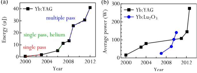
The combination of the SESAM and the TDL concepts results in a power scalable ultrafast technology. Simply increasing the pump power with both an increased pump spot area on the disk and laser spot area on the SESAM allows one to increase the output power of SESAM modelocked TDLs. This resulted in a steady increase of the average power and pulse energy available from such modelocked sources since their first demonstration in the year 2000 [16] (Figure 1). Currently, SESAM modelocked TDLs achieve higher average powers (>275 W [17]) and pulse energies (>40 μJ [18]) than any other oscillator technology.
Figure 1. Evolution of pulse energy (a) and average power (b) of ultrafast semiconductor saturable absorber mirrors (SESAM)-modelocked thin-disk laser (TDLs). Most power and energy scaling was achieved using the well-established gain material Yb:YAG, but promising new materials for this application are currently the topic of important research efforts.
(a)
(b)
In this paper, we will review recent progress in the performance of modelocked TDLs. The average power of ultrafast oscillators recently reached a new limit with the demonstration of a SESAM
modelocked TDL with 275 W—the highest average power reported from an ultrafast oscillator to date. The laser was based on the gain material Yb:YAG and operated with a pulse duration of 583 fs and a pulse energy of 16.9 μJ. This performance was obtained by operating the modelocked laser in a vacuum environment to eliminate the parasitic nonlinearity of the air inside the oscillator. We will summarize the results obtained using this new approach, which represents an important step forward towards the kilowatt average power level milestone. Another key element to achieve this latest step in power scaling was the availability of SESAMs with high-damage threshold and parameters suitable for high-power operation. A recent investigation, which targeted to specifically explore damage behavior of SESAMs for such high-power oscillators [19], enabled the fabrication of such robust samples. We will review the guidelines developed in this recent study and discuss future improvements.
Another major milestone for modelocked TDLs is to extend the high-power capabilities of TDLs to the sub-100 fs regime. This topic is intimately linked to the development of novel broadband materials suitable for this geometry [20]. Recently, the limits in terms of pulse duration of modelocked TDLs based on different gain materials were explored. As a result, a first important step in this direction was achieved, with the demonstration of sub-100 fs pulses from a TDL based on the sesquioxide gain material Yb:LuScO3 (Yb:LuScO) [21]. In this first experiment, sub-100 fs operation was achieved at
moderate average output powers (5 W). However, preliminary power scaling experiments indicate that much higher output powers are within reach. Furthermore, the intracavity peak power levels achieved are already high enough for preliminary intralaser nonlinear optics experiments, which is a promising application [22].
The progress achieved in the pulse duration of TDLs enabled us to explore for the first time the carrier-envelope phase properties of a TDL based on Yb:Lu2O3 (Yb:LuO) that delivered 7 W and 142 fs
pulses. We measured the carrier-envelope offset (CEO) frequency, which is the first key step towards full stabilization of such a source [22]. This experiment shows that TDLs are also excellent candidates for applications in spectroscopy and metrology, where high-power frequency combs are of interest.
Finally, we will conclude with an outlook towards higher average powers, higher pulse energies and higher peak powers from TDLs.
2. Average Power Scaling of Modelocked Thin-Disk Lasers: Challenges and Milestones
Several issues have, so far, limited scaling of modelocked TDLs to average output powers in the kilowatt range. One challenge is achieving fundamental transverse mode operation at high average powers, which is a crucial aspect for stable passive modelocking. As a result, average power and energy scaling of passively modelocked TDLs goes hand-in-hand with progress in power scaling of TDLs operating in single fundamental transverse mode. In most bulk lasers, thermal aberrations that occur in the gain medium mainly limit the available power. TDLs are ideally suited to partially overcome this limitation. Significant efforts have been carried out in the past years to optimize fabrication and contacting of standard thin gain media to minimize these thermal aberrations, in particular for the most commonly used gain material for TDLs, Yb:YAG [12,23,24]. Until now, 500 W of continuous wave (cw) power with diffraction limited beam quality (M2 < 1.1) have been demonstrated using one disk based on this material [25]. For novel gain materials such as Yb:LuO or Yb:LuScO, small residual thermal lensing can be compensated by adapting the resonator design [26]. These novel
materials such as Yb:LuO have a large potential to outperform Yb:YAG in terms of efficiency and pulse duration, when growth and contacting techniques are perfected. The challenges of achieving single-transverse mode operation from high-power TDLs in the context of modelocking have already been discussed in detail in reference [27]. Here, we will focus on the challenges of achieving soliton modelocking at high average powers and high pulse energies.
One important point is avoiding an excessive nonlinear phase shift due to self-phase modulation (SPM) that can destabilize the pulses in the soliton modelocking regime [28,29]. In the past, the dominant source of unwanted SPM was the nonlinearity of air. We will discuss different approaches that have been demonstrated in the past years to reduce this parasitic nonlinearity. In particular, a new approach to overcome this limitation in the context of modelocked TDLs was recently demonstrated, which consists of operating the oscillator in a vacuum environment. In this way, the nonlinearity of the ambient environment is reduced by several orders of magnitude enabling high average powers and pulse energies in simple oscillator geometries, with a low number of passes through the gain medium and low output coupling rates. Furthermore, only a small amount of dispersion is required even at very high intracavity pulse energy to compensate for this phase shift within one round-trip in the laser cavity. With this approach, the latest step in average power scaling was achieved, reaching an average power of 275 W at a pulse duration of 583 fs using the well-established gain material Yb:YAG. The laser operates at a repetition rate of 16.3 MHz resulting in a pulse energy of 16.9 μJ and a peak power of 25.6 MW. We will review this latest step in power scaling, which opens the door to future kilowatt-level oscillators.
Another point that has only recently been investigated is possible limitations of SESAMs in terms of damage and lifetime. As a result of a detailed investigation, simple guidelines to design robust SESAMs with high-damage thresholds and optimized parameters for operation at extreme intracavity conditions were recently developed [19]. This is a crucial point for future kilowatt-level oscillators. We will review these guidelines and discuss further improvements.
Ultimately, thermal effects and damage that occur in different cavity components limit average power scaling of modelocked TDLs. This is particularly the case in simple thin disk oscillator geometries with low gain per roundtrip, where the circulating intracavity power can reach several kilowatts of average power. We will discuss critical points and future improvements.
2.1. Harnessing Intracavity Nonlinearity
In a typical cavity for a soliton modelocked TDL (Figure 2), the circulating pulse experiences SPM by propagating through nonlinear materials like the gain medium, a Brewster plate and the air atmosphere. Most commonly, the disk is used as a folding mirror in a linear cavity, resulting in 4 gain passes through the thin disk. This configuration is usually referred to as a “single-pass” configuration. A Brewster plate is most commonly used to obtain a linearly polarized output and for fine adjustment of the SPM by placing it at a position in the cavity where there is a focus. Negative dispersion is introduced with dispersive mirrors throughout the cavity. Most commonly, Gires Tournois Interferometer (GTI)-type mirrors are used because they can provide large amounts of negative dispersion [30,31] required for stable soliton modelocking at the pulse durations typically obtained in state-of-the-art TDLs.
Figure 2. Typical layout of a modelocked TDL cavity. HR: highly-reflective mirror, OC: output coupling mirror, DM: dispersive mirror.
thin disk Brewster plate HR DM OC SESAM
The total nonlinear phase shift Фnl accumulated by the pulses due to self-phase modulation (SPM)
per cavity round trip is given by
nl 2 2
n2(z)I(z)dz
cav
(1)Most commonly, the γ-factor (in mrad/MW) is used, which is independent of the pulse parameters but takes into account the different spot sizes of the beam throughout the cavity.
nl 42 Ppk n2(z) A(z)dz cav
Ppkcav (2)Therefore, the γ-factor can be written as:
cav 42
n2(z)
A(z)dz
cav
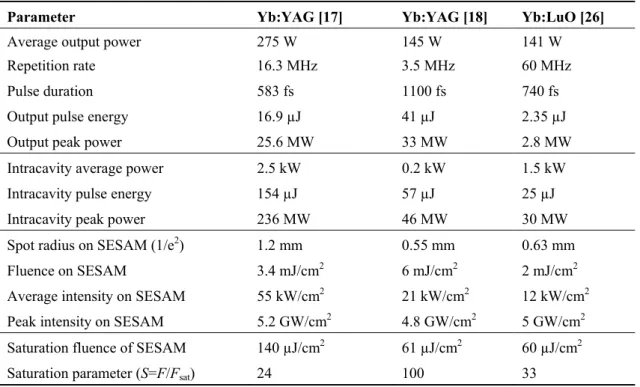
(3)Different elements in the cavity contribute to the total γfactor and the total nonlinear phase shift undergone by the pulses. In Table 1, the contribution of these different elements to the total nonlinear phase shift in state-of-the-art modelocked thin disk lasers is presented.
Table 1. Summary of performance and contribution of different cavity elements to nonlinear phase shift due to self-phase modulation (SPM) in state-of-the-art high-power TDLs.
Parameter Yb:YAG [32] Yb:YAG [17] Yb:YAG [18] Yb:LuO [26]
Average output power 44 W 275 W 145 W 141 W Repetition rate 4 MHz 16.3 MHz 3.5 MHz 60 MHz Pulse duration 791 fs 583 fs 1100 fs 740 fs Output pulse energy 11.3 µJ 16.9 µJ 41 µJ 2.35 µJ Output peak power 12.6 MW 25.6 MW 33 MW 2.8 MW Intracavity average power 450 W 2.5 kW 0.2 kW 1.5 kW Intracavity pulse energy 113 µJ 154 µJ 57 µJ 25 µJ Intracavity peak power 127 MW 236 MW 46 MW 30 MW Nonlinear phase shift environment Фenv helium 108 mrad vacuum 8 mrad air 1725 mrad air 44 mrad
Nonlinear phase shift
Brewster plate ФBP 95 mrad 17 mrad - -
Nonlinear phase shift disk Фdisk 19 mrad 3 mrad - 4 mrad
Other nonlinear phase shifts Фother - 45 mrad - -
Total nonlinear phase shift Фcav 222 mrad 75 mrad 1725 mrad 48 mrad GDD per roundtrip −20,000 fs2 −8,100 fs2 −346,500 fs2 −9,900 fs2
Gain material:
The SPM from the disk can typically be neglected as the laser mode size on the disk is large and the pulse passes only through very little material.
Brewster plate:
The influence of the Brewster plate can be controlled by the choice of the thickness, the material and the mode size at the location in the cavity where it is placed. Usually, the presence of a Brewster plate is beneficial as it offers control over the total amount of SPM when placed at a position in the cavity close to a focus, and ensures linear polarization of the laser output. In cavities where a fine control of the SPM can be achieved otherwise (for example with the air pressure, when the oscillator is operated in a vacuum chamber) a thin-film polarizer can be chosen instead of a Brewster plate to select the polarization.
Cavity optics:
The nonlinearity introduced by the coatings of different cavity optics has been, until now, always considered negligible. However, in simple cavities where a low number of passes through the gain medium is chosen, they can become an important contribution to the total soliton phase shift at extreme intracavity peak powers.
Air atmosphere:
The contribution of the air atmosphere was initially ignored, since the nonlinear refractive index n2,atm is orders of magnitude smaller than the refractive index of, for example, a fused-silica
Brewster plate. However, typical MHz TDLs have cavity lengths in the order of several meters to several tens of meters. Furthermore, in most modelocked TDLs, the intracavity peak power is substantially higher than the output peak power and can exceed 100 MW [17,32]. Therefore, intracavity SPM introduced by the ambient air in the cavity can become the main contribution to the total soliton phase shift [33]. In order to compensate for this phase shift and obtain stable soliton modelocking, large amounts of negative GDD are required. If this phase shift becomes excessive (typically larger than some hundred mrad), modelocked operation is destabilized [28,34]. Different approaches have been suggested in the past years to overcome this limitation:
- Helium flooding
Helium has a nonlinear refractive index n2 that is approximately 8 times smaller than air
(n2,air ≈ 3·10−23 m2/W, [35] and n2,He ≈ 0.4·10−23 m2/W [36]). Therefore, replacing the air in the
cavity by helium enabled the demonstration of the 10 µJ pulse energy milestone in 2008. In this result, 11 µJ were obtained at an average power of 44 W from a SESAM modelocked TDL based on Yb:YAG [32]. In this oscillator, the disk was used in a single-pass configuration, resulting in a high intracavity pulse energy of >110 µJ. The required dispersion to generate the 791-fs pulses was, in this case, −20,000 fs².
- Multiple gain passes through the same disk
Another approach to lower the SPM in the cavity is to reduce the intracavity peak power by using a higher output coupler transmission. An important advantage of this approach is that the fluence on the SESAM and the thermal load on all components inside the laser cavity are reduced. Efficient laser operation with a higher output coupling transmission is only possible if the gain per cavity round trip is increased accordingly. This can be achieved by multiplying
the number of passes through the same gain disk, which results in an increased overall gain per cavity roundtrip. This geometry, most commonly referred to as “active multi-pass cell” in a modelocked TDL, was introduced by Neuhaus et al. [37,38]. Using this approach, 145 W of average power were demonstrated with a pulse energy of 41 µJ using a 72% output coupling transmission and 11 passes through the Yb:YAG thin disk [18]. In this case, the intracavity pulse energy was below 60 µJ and operation in air was possible with a total GDD of −236,000 fs2. In addition to the large amounts of negative GDD required in this approach, a large amount of passes through the thin disk significantly increases the demands on the disk quality, since the cavity stability zones shrink significantly with the number of passes [27]. Another potential disadvantage is the reduced Q-factor of the cavity, resulting in a higher intrinsic noise level. Furthermore, a larger gain per roundtrip results in longer minimum achievable pulse duration [28,29]. This is not an issue in industrial applications such as high-speed micromachining, where obtaining short pulse duration is not of critical importance. In the case of scientific applications, shorter pulse durations are more critical, in particular since it simplifies further pulse compression schemes.
- Multiple gain passes through different disks
The combination of several laser heads in one cavity has already been demonstrated [12], but not in the context of modelocked TDLs. In this case the main difficulty is to achieve fundamental mode operation, as each disk can show a different thermal lensing behavior. - Vacuum environment
Operating the oscillator in vacuum by placing it in a vacuum chamber allows for a reduction of the nonlinearity of the ambient environment by several orders of magnitude, since the nonlinear refractive index n2 parameter varies linearly with air pressure for medium vacuum
levels [39]. In addition to a minimal nonlinear phase shift at very high intracavity peak power levels, the advantages of operating the oscillator in vacuum are many-fold:
- Fine adjustment of the air pressure inside the cavity enables one to tune the nonlinear phase shift and minimize the pulse duration at a given output power. This eliminates the need for a moving Brewster plate in the cavity that can introduce aberrations and small losses.
- The low amount of nonlinearities allows one to operate in simple oscillator geometries with low gain per cavity round-trip (one or two passes on the disk used as a folding mirror in the cavity).
- Only small amounts on negative GDD are required to compensate for the small nonlinear phase shifts even at high intracavity peak powers. This results in lower parasitic losses and thermal effects that can occur in the dispersive mirrors.
- Turbulences of air and related pointing instabilities are minimized.
- Operating in a moderate vacuum environment allows for keeping the oscillator optics clean, which is critical at high intracavity powers.
- In addition to the above-mentioned points, developing robust vacuum oscillator technology will facilitate future intracavity HHG experiments, for which operation in
vacuum is essential to avoid UV-light absorption by air. Furthermore, for other nonlinear experiments, one could consider flooding the chamber with other gases. On the other hand, heat convection due to air is nearly completely eliminated by operating the oscillator in vacuum. In our experiment, we observed increased thermal effects in critical optics such as the dispersive mirrors when the oscillator was operated in vacuum. Nevertheless, using thermally improved mirrors and/or actively cooling these critical elements in the cavity (in the same way the disk or the SESAM are cooled) can solve these issues.
The advantages of this promising new approach were recently confirmed for the first time with the demonstration of a thin disk oscillator with 275 W [17]. In the next paragraph, we will summarize this recently achieved power scaling result which paves the way to even higher average output powers and pulse energies from such ultrafast oscillators.
2.2. State-of-the Art Modelocked Thin-Disk Laser with 275 W of Average Power 2.2.1. Experimental Setup and Results
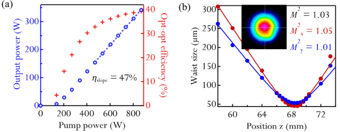
The gain element used was a commercial Yb:YAG thin disk glued on a water-cooled diamond heatsink (TRUMPF GmbH). The disk was ≈100 μm thick. The thin-disk head was arranged for 24 pump passes through the disk and a pump spot diameter of 4.7 mm. The disk was pumped at its broad absorption line at 940 nm. The measurement of the thermal lensing of this disk showed no significant thermal lensing over the whole pump power range used throughout the experiment, which allowed for robust fundamental transverse mode operation. We used an outcoupling rate of 11.4% for the modelocking experiment, and obtained up to 340 W of cw power at an optical-to-optical efficiency of 39.2% with a diffraction-limited beam (M2 < 1.05) (Figure 3).
Figure 3. (a) cw fundamental transverse-mode operation with the same output coupler as for the modelocking experiment, using only highly reflective mirrors as cavity mirrors and without polarization control of the laser; (b) M2 measurement at the maximum power of 340 W. Inset: Picture of the laser mode at the maximum cw output power.
(a) (b)
A set of five dispersive mirrors in the cavity introduced approximately −8100 fs2 of negative GDD per roundtrip, required for soliton modelocking. A fused silica plate with a thickness of 700 µm was inserted at Brewster’s angle for polarization selection. It was introduced at a fixed position in the
cavity where the beam had a large radius of ≈1.3 mm. This controls the laser polarization with minimal SPM. Fine control of the total SPM was achieved by changing the pressure in the vacuum chamber by introducing small amounts of nitrogen.
The SESAM used in this experiment was designed for high damage threshold and high-power modelocking following the guidelines presented in reference [19] and summarized in paragraph 2.3 of this paper. Special attention was paid during fabrication to obtain a large homogeneous sample for future spot size scaling (Figure 4). It consists of a distributed Bragg reflector (DBR) and three 10-nm InGaAs quantum wells (QWs) as absorbers in an antiresonant configuration. A dielectric topcoating that consists of 3 quarter-wave pairs of SiO2/Si3N4 was deposited by plasma enhanced chemical vapor
deposition (PECVD). Nonlinear reflectivity and recovery measurements of this sample yielded a saturation fluence Fsat = 140 μJ/cm2, a modulation depth ΔR = 0.95%, nonsaturable losses ΔRns = 0.1%
and a recovery time τ1/e=67 ps. The vacuum chamber (Figure 4) was operated at a constant air pressure
of 0.5 mbar, which was the lowest value that could be obtained in our setup and with the available vacuum pump.
Stable cw modelocking was obtained for average powers ranging from 135 W to 275 W (Figure 5d). When trying to reach higher power levels, the optical-to-optical efficiency decreased but no modelocking instabilities were observed. In order to avoid possible damage of the thin disk, the pump power was not further increased. At the maximum power of 275 W, the pulse duration was 583 fs (Figure 5a). The optical-to-optical efficiency was 32.4%, corresponding to an incident pump power of 839 W. The pulses had a time bandwidth product of 0.329 (ideal sech2 0.315), determined with the measured spectral bandwidth of 2 nm (Figure 5b). The repetition rate of the pulses was 16.3 MHz (Figure 5c), resulting in a pulse energy of 16.9 μJ. The corresponding peak power of the pulses is 25.6 MW. Operation with a single pulse circulating in the cavity was confirmed using a fast photodiode (25 GHz) and a sampling oscilloscope. Furthermore, the delay of the autocorrelator (80 ps) was scanned in search for cross-correlations of potential parasitic pulses with the main pulse. The beam at the maximum modelocked average power level was nearly diffraction limited with an M2 < 1.05.
Figure 4. Vacuum chamber where the oscillator was built and schematic setup of the 16.3 MHz pulse repetition rate fundamental transverse mode cavity used for the high-power modelocking experiment. Inset: Picture of large scale SESAM used for this experiment.
1.6 m
0.9 m
HR OC SESAM DM to diagnostics
Figure 5. (a) Autocorrelation trace of the pulses at the maximum average output power of 275 W; (b) Optical spectrum of the pulses; (c) Radio frequency spectrum of the pulses, with a resolution bandwidth of 30 kHz; (d) Output power and optical-to-optical efficiency in modelocked operation as a function of pump power. The points before modelocking were not measured in order to avoid damage of intracavity components during the Q-switched modelocking (QML) regime that occurs before modelocked operation.
(a)
(b)
(c)
300 250 200 150 100 Out put powe r (W ) 800 700 600 500 Pump power (W) 30 20 10 0 O pt-o pt ef ficienc y ( % )(d)
2.2.2. DiscussionInside the oscillator, the circulating pulses had an energy of 146 μJ, and a peak power of 220 MW. In contrast to previous high-power modelocked TDLs, the nonlinearity of the ambient environment was not the main contribution to the total SPM phase shift (Table 1). Assuming soliton pulses, the dispersion introduced in our cavity compensates for a nonlinear phase shift of approximately 75 mrad at the maximum power and for the obtained pulse duration. The atmosphere in the cavity only contributes ≈8 mrad to this total phase shift, assuming a linear behavior of the nonlinear refractive index of air with the pressure in the vacuum chamber [35,39]. The Brewster plate accounts for ≈17 mrad and the thin disk for ≈3 mrad. The remaining phase shift (≈47 mrad) seems to originate from nonlinearities due the high intensities on the different cavity mirrors. In our current layout, some of the dielectric mirrors used in the cavity withstand intensities >50 GW/cm2. At these high peak intensities, even a small penetration depth can lead to a significant phase shift. However, in order to precisely evaluate
the contribution of each mirror to the total phase shift, the exact structure and material composition of these commercial mirrors needs to be precisely known. This point is currently being investigated.
In spite of these very high intracavity intensities, no damage was observed on the SESAM. The main limitation to higher average powers in our current configuration was thermal effects and even damage that occurred in the dispersive mirrors. Improved dispersive mirror designs with better thermal properties will allow for higher average power in the future.
2.3. SESAMs for High-Power Femtosecond Modelocking 2.3.1. SESAMs in High-Power Ultrafast Oscillators
As we mentioned in the previous paragraph, SESAMs with high-damage threshold and appropriate macroscopic parameters are one of the key points for power scaling of ultrafast oscillators. A specific investigation of damage and lifetime of SESAMs designed for high-power oscillators is therefore crucial. Previous investigations on optimized SESAM designs mostly focused on the realization of low saturation fluences [40,41], which is key for high repetition rates and stable modelocking of semiconductor lasers [34]. A recent investigation carried out in the context of high-energy modelocked TDLs focused on studying the influence of nitrogen incorporation on the carrier dynamics of SESAMs, but damage was not investigated [42].
SESAMs for high-power ultrafast TDLs operate in a regime in which pulse energies and average power levels are several orders of magnitude higher than in standard low-power femtosecond oscillators. In Table 2, we present typical SESAM operation parameters in recently demonstrated high-power thin-disk oscillators. We notice that SESAMs in such oscillators operate at kilowatt intracavity power levels, peak intensities of gigawatts per square centimeter, and fluences above the millijoule per square centimeter level. The saturation parameter (S-parameter, S = F/Fsat) is a useful
parameter to describe operation of a SESAM in a laser cavity. Typical SESAM modelocked lasers operate at S = 3–10 [29], but, as we can see from Table 2, stable operation with S parameters larger than 20 is common in high-energy oscillators. Operation at high S-parameters makes multi-pulsing instabilities a critical issue in TDLs. In particular, the additional absorption observed at high fluences caused by induced absorption (IA) causes a “rollover” in reflectivity. Operating the SESAM close to this rollover can lead to multi-pulsing instabilities [43–45] because in this case multiple pulses with lower pulse energy can have a gain advantage compared to single pulses.
Therefore, the most crucial parameters of SESAMs for high-power oscillators are:
- large saturation fluences to operate at moderate saturation parameters and with small spot sizes, which relaxes cavity sensitivity to alignment and possible thermal lensing,
- high damage thresholds,
- low nonsaturable losses to avoid thermal effects,
- reduced induced absorption (IA), which is responsible for the reflectivity rollover at high fluences and can lead to multi-pulsing instabilities [43–45].
The study presented in [19] focuses on how to tailor and combine suitable parameters for high-power operation and high-damage thresholds. As we have mentioned in paragraph 2.2, the latest average-power scaling step was made possible thanks to the guidelines established during this investigation.
Table 2. Typical operation parameters of SESAMs in state-of-the-art high-power TDLs.
Parameter Yb:YAG [17] Yb:YAG [18] Yb:LuO [26]
Average output power 275 W 145 W 141 W Repetition rate 16.3 MHz 3.5 MHz 60 MHz Pulse duration 583 fs 1100 fs 740 fs Output pulse energy 16.9 µJ 41 µJ 2.35 µJ Output peak power 25.6 MW 33 MW 2.8 MW Intracavity average power 2.5 kW 0.2 kW 1.5 kW Intracavity pulse energy 154 µJ 57 µJ 25 µJ Intracavity peak power 236 MW 46 MW 30 MW Spot radius on SESAM (1/e2) 1.2 mm 0.55 mm 0.63 mm
Fluence on SESAM 3.4 mJ/cm2 6 mJ/cm2 2 mJ/cm2
Average intensity on SESAM 55 kW/cm2 21 kW/cm2 12 kW/cm2
Peak intensity on SESAM 5.2 GW/cm2 4.8 GW/cm2 5 GW/cm2
Saturation fluence of SESAM 140 µJ/cm2 61 µJ/cm2 60 µJ/cm2
Saturation parameter (S=F/Fsat) 24 100 33 2.3.2. Experimental Setup and Measurement Procedure
In order to reach the high fluences necessary to carry out this study, we used a high-energy SESAM modelocked Yb:YAG TDL seeding a high-precision nonlinear reflectivity measurement setup to characterize nonlinear reflectivity, IA, and damage of our SESAMs. The experimental setup is presented in Figure 6, and in more detail in reference [46]. The SESAM modelocked Yb:YAG TDL delivers 15 W of average power at a repetition rate of 10.7 MHz, corresponding to a pulse energy of 1.4 μJ in 1-ps pulses, which allowed testing SESAMs up to an unprecedentedly high fluence of 0.21 J/cm2.
Figure 6. (a) Experimental setup used for the nonlinear reflectivity characterization and damage measurements; (b) Typical measurement of nonlinear reflectivity measured using this setup, and important macroscopic parameters extracted using a least-squares fitting procedure [47].
Formula (4) describes the fluence-dependent SESAM reflectivity R(F) for a flat-top-shaped beam profile [47]: R(F)Rns ln 1Rlin Rns e F Fsat1 F Fsat e F F2 (4)
A typical measurement and the important extracted macroscopic parameters using this formula with a numerical correction for a Gaussian beam profile are presented in Figure 6. These parameters are:
- The modulation depth ΔR, which represents the maximum achievable change in reflectivity. - The nonsaturable losses ΔRns represent the unsaturable fraction of the reflectivity which
originate from defect absorption, scattering, free-carrier absorption, carrier heating, etc. - The saturation fluence Fsat represents, in the case of moderate modulation depths (up to
approximately 10%), the fluence at which 1/e of the modulation depth has been saturated. - The IA coefficient F2, which characterizes the strength of the reflectivity rollover that occurs
at high fluences. In the case of femtosecond pulses, two-photon absorption (TPA) is the main cause of IA [19,45]. However, for longer pulse durations, studies show that the measured rollover is stronger than predicted by TPA only, indicating that other effects need to be considered, such as free-carrier absorption, or hot-carrier generation [43,45,48].
In addition to the nonlinear reflectivity parameters, this setup was used to measure the damage fluence and lifetime of different representative SESAMs. In this study, damage was defined as an irreversible change in the structure resulting in a dramatic drop in the measured reflectivity. The damage fluence threshold Fd is then defined as the minimum fluence where this irreversible reflectivity
drop occurs in <1 s. In order to measure the damage fluence and the time-to-damage of a sample we use the same setup described in the first section for nonlinear reflectivity measurements. We set the fluence to a constant value and track reflectivity of the sample versus time. In this way, we can measure the lifetime of different samples by evaluating the time-to-damage at fluences lower than the damage fluence.
2.3.3. Studied Structures and Obtained Results
A common approach to increase the saturation fluence of a SESAM consists of growing a top mirror on the structure to increase its finesse. In this way, the electric field in the absorber layers is reduced and the fluence required to saturate the sample is increased. As we increase the saturation fluence, we reduce the modulation depth of the sample by the same factor, since Fsat·ΔR = Ft with Ft
the transparency fluence of the absorber. The product Fsat·ΔR remains constant for a given absorber
section since the transparency fluence only depends on intrinsic material properties [19,49]. This means that the samples to topcoat need to have a large enough modulation depth in addition to the basic requirements (i.e., low nonsaturable losses and an initially large saturation fluence). With multiple QWs, we can adjust the modulation depth without changing the saturation fluence of the samples.
The design of the non-topcoated SESAM (NTC) used for this study consists of a 30-pair GaAs/AlAs DBR and three 10-nm InGaAs QWs as absorber layers in an antiresonant configuration.
The QWs of this sample were grown at T ≈ 400 °C, resulting in a recovery time at 1/e of τ1/e ≈ 200 ps and low nonsaturable losses <0.1%.
Three different topcoatings were grown on this structure. In the first case, a semiconductor topcoating was chosen with four pairs of quarter-wave GaAs/AlAs layers (semiconductor topcoating (SCTC), see Figure 7b) grown by molecular beam epitaxy (MBE). In this design, the field enhancement in the absorber is reduced by a factor of ≈4 compared to the uncoated sample (see Figure 7d). Therefore the same increase of the saturation fluence is expected. For the other cases, a dielectric SiO2/Si3N4
topcoating deposited by plasma-enhanced chemical vapor deposition (PECVD) was chosen. Two sets of samples were coated with two and three pairs of quarter-wave layers (DTC2 and DTC3, see Figure 7c). In this case, we expect an increase of the saturation fluence by a factor of 3 and 5, respectively Figure 7d. The dielectric topcoating can be applied after MBE growth, which allows for additional flexibility in terms of finesse change of the structure. From a material point of view, SiO2 and Si3N4 are dielectric
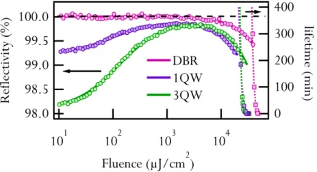
materials, and therefore exhibit negligible TPA compared to GaAs [50], which results in reduced IA. Figure 7. Different SESAM structures used for the damage studies (a) SESAM design with 3 QWs and no topcoating (NTC); (b) same SESAM but with a 4-quarter-wave-pair GaAs/AlAs semiconductor topcoating (SCTC); (c) same SESAM but with a 3-quarter-wave pair SiO2/Si3N4 dielectric topcoating (DTC3); (d) field enhancement in the absorber section.
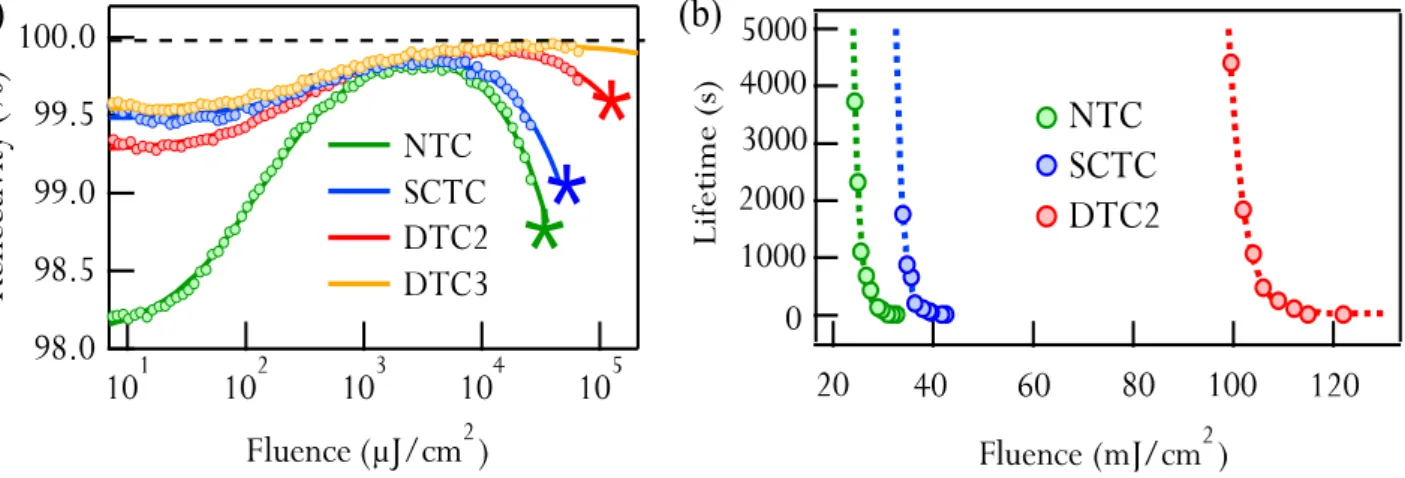
Figure 8. (a) Damage threshold (indicated with a star) of the different tested SESAMs together with their nonlinear reflectivity measurement; (b) Lifetime curves of different representative SESAMs, where one can see a large shift of the lifetime of the sample with a dielectric topcoating to higher fluences. The sample with a 3-pair dielectric topcoating (DTC3) could not be damaged at the maximum available fluence in our setup of 0.21 J/cm2.
(a)
(b)
The nonlinear reflectivity measurements and corresponding extracted parameters are presented together with the measured damage thresholds in Figure 8a, and Table 3. We can clearly see the effect of the different topcoatings on the saturation parameters of the samples: as the saturation fluence increases, the modulation depth decreases by a similar factor. The saturation fluences of all the topcoated samples are larger than 150 μJ/cm2 and their modulation depths are between 0.4% and 0.8%. The 3-QW non-topcoated sample with 2% modulation depth is ideally suited for topcoatings designed for a saturation fluence increase of 3–5. All SESAMs have negligible nonsaturable losses <0.1% and therefore minimal thermal load.
Table 3. Damage thresholds of the different representative SESAMS together with their saturation parameters. The samples with a 3-pair dielectric topcoating did not show damage up to the maximum available fluence in our setup of 0.21 J/cm2.
Sample Fsat (μJ/cm2) ΔR (%) ΔRns (%) F2 (mJ/cm2) Fd (mJ/cm 2) S d = Fd/Fsat NTC 72 2.05 <0.1 3200 32.6 450 SCTC 279 0.52 <0.1 5500 44.1 158 DTC2 168 0.71 <0.1 31700 122 726 DTC3 247 0.43 <0.1 346000 >210 >850
In terms of IA, all topcoated SESAMs have increased F2 coefficients compared to that of the
non-topcoated sample. However, the semiconductor topcoated SESAM (SCTC) shows only a small increase compared to the dielectric topcoated samples (DTC2 and DTC3). Although the field in the DBR structure and the absorber section is reduced in all samples, the GaAs/AlAs topsection experiences a strong electric field, and GaAs has a strong TPA coefficient. In the case of the dielectric topcoating, both materials have a negligible TPA coefficient compared to GaAs. Therefore, SESAMs with similar saturation parameters (similar electric field distributions in the DBR and the absorber region) but different topcoatings have different IA responses.
The topcoated SESAMs show, in all cases, higher damage fluences than without a topcoating. The damage fluences for the dielectric topcoated SESAMs (DTC2 and DTC3) are much higher than for the semiconductor topcoated SESAM (SCTC) with similar saturation parameters. It is interesting to note that regardless of the sample, instantaneous damage occurs at fluences deep in the rollover regime, where SESAM modelocked lasers would not operate in a stable regime (e.g., saturation parameters larger than 150). However, the higher damage threshold is beneficial to overcome the Q-switched modelocking (QML) regime usually observed before modelocking [51], regime where peak powers can be significantly larger than in stable cw-modelocking. Furthermore, the lifetime of these samples is longer, which is of interest for long-term operation. For our sample with 3 quarter-wave pairs dielectric topcoating (DTC3), damage was not observed even at the maximum available fluence in our setup of 0.21 J/cm2. This particular sample was tested at this maximum fluence level for several hours and no damage was observed.
Lifetime curves were measured in this high-fluence regime (Figure 8b), showing a clear exponential behavior for all samples. This suggests lifetimes of several 10,000 hours at standard operation parameters. However, it is likely that other mechanisms need to be taken into account to correctly evaluate the lifetime at much lower fluences.
2.3.4. Damage Mechanism
The damage fluence measurements presented in the previous paragraph suggest a damage mechanism related to the absorbed energy due to IA. It is interesting to note that in the case of the sample with 3 QWs and a two-pair dielectric topcoating (DTC2) where F2 is greatly increased, the damage curve is
also shifted to higher values. In order to confirm this point, the damage behavior of a SESAM with a single QW absorber, one with 3 QWs, and a DBR mirror (without absorber section) were compared (Figure 9 and Table 4). This is crucial to evaluate if the damage threshold is dependent on the absorber geometry. All the samples have no topcoating, and were grown in an antiresonant configuration.
Figure 9. Nonlinear reflectivity and lifetime measurements for a (distributed Bragg reflector) (DBR), a SESAM with 1 QW as an absorber and a similar SESAM with 3 QWs as absorbers.
Table 4. Relevant parameters and damage thresholds of the samples with different absorber sections.
Sample Fsat (μJ/cm2) F2 (mJ/cm2) Fd (mJ/cm2) Sd = Fd/Fsat
DBR - 7400 48 -
1 QW 57 2600 32.1 560
3 QW 72 3200 32.6 453
We can see (Figure 9 and Table 4) that the damage behavior of a DBR is similar to that of the characterized SESAMs. Damage occurs deep in the rollover regime, and this rollover occurs at comparable fluence levels as for all tested SESAMs. The measurements confirm that the damage mechanism is related to the absorbed energy due to IA. This fraction of absorbed energy per area Fabs
due to the IA can be evaluated at in incident fluence F taking into account a number of approximations [19] by:
FabsF2
F2 (5)
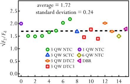
Therefore, the damage fluence Fd for all SESAMs should scale proportionally to √F2. In order to
illustrate this dependence, we plotted the ratio √F2/Fd for 16 different samples for which we were able
to measure the damage fluence (Figure 10).
Figure 10. Ratio √F2/Fd for different samples for which we measured the damage
threshold, including samples with different absorber sections and a DBR mirror.
The data seems to confirm that the main contribution to IA and damage originates in the field in the DBR and spacer layers and not by the absorber section itself. This gives a clear indication of the damage behavior of such SESAMs, suggesting that catastrophic damage occurs due to heating of the lattice by energy absorbed by the IA process. It also indicates how to shift the damage fluence to higher values by simply increasing F2.
2.3.5. Influence of Growth Temperature
In some specific cases, additional requirements on the SESAM parameters can be beneficial to push the oscillator performance to its limits. For example, in the case of TDLs where short pulses are targeted and a large fraction of the bandwidth needs to be exploited, a somewhat higher modulation depth and faster recovery time are beneficial [20,28,29]. Achieving shorter recovery times is straightforward with low-temperature (LT) growth [52]. The results presented in the previous paragraph indicate that growing the QWs at lower temperature should only have a small influence on the damage threshold of the samples, since the damage threshold is nearly independent of the absorber section. However, an experimental verification of this point is crucial, in particular given the higher nonsaturable losses expected from such LT-grown QW-SESAMs. In this paragraph, we will present measurements that confirm that the growth temperature of the QWs has only a small influence on the damage threshold, indicating that the guidelines presented in the previous paragraph can also be applied to fast samples with non-negligible nonsaturable losses.
Experimental Setup
In order to carry out this study, we measured the nonlinear reflectivity, damage threshold and recovery parameters of a set of representative samples. For the nonlinear reflectivity and the damage threshold measurements, we used the same setup and experimental procedure described in 2.3.2. To measure the recovery time of the samples, we used a standard pump-probe setup (Figure 11) seeded by a bulk Yb:YAG laser delivering 1-ps long pulses at a repetition rate of 38 MHz and 150 mW of average power. The laser operates at a central wavelength of 1030 nm. For the study of the influence of the absorber growth temperature, we used samples with a larger number of QWs than in the damage and lifetime investigation presented in the previous paragraph in order to reach an initially larger modulation depth. The structure consists of a standard DBR and four InGaAs QW absorbers embedded in GaAs. The absorbers were placed two-by-two in two consecutive antinodes of the electric field pattern to optimize their absorption. This resulted in samples with more than 3% modulation depth, which can be further coated to decrease their modulation depth. The QW absorbers of the four samples used for this study were grown at different temperatures (245 °C, 270 °C, 300 °C, 385 °C). The samples were designed for an operation wavelength of 1030 nm.
Results
In Figure 12a, pump-probe measurements of these samples are shown, confirming as expected that samples grown at lower temperatures have faster recovery times [52]. In Figure 12b, we plot the characteristic decay time to 1/e (τ1/e) as a function of QW growth temperature. The
observed behavior confirms previous studies carried out with LT-grown GaAs [52]. Although the parameter τ1/e is not sufficient to fully characterize the dynamics of the absorber, it is an
appropriate simplified parameter to compare the recovery of the absorber in a passively modelocked solid-state laser. In Figure 12c, we plot nonsaturable losses and damage threshold of these samples as a function of the growth temperature. The total nonsaturable losses of the samples decrease exponentially with the growth temperature, which also confirms the observations made in reference [52]. It is interesting to point out that even for our fastest sample with a
recovery time of ≈2 ps the nonsaturable losses stay low in comparison to the modulation depth of the sample (1.2% nonsaturable losses for 3.9% modulation depth). For use in most common TDLs, lower modulation depth is required. Therefore a dielectric topcoating that will reduce the field in the absorber will be applied, further reducing the nonsaturable losses. The measured increase in damage threshold with growth temperature is relatively small compared to the decrease in the recovery time of the absorber (we observe a decrease of 40% in damage threshold, for a 12-fold decrease of the nonsaturable losses). Heating of the absorbers due to the additional defects most likely causes this small decrease in the damage threshold of the samples.
Figure 11. Pump-probe setup used for measuring the recovery dynamics of the different SESAMs. AOM: Acousto-optic modulator.
Figure 12. (a) Pump-probe measurements of samples with the same structure, but with the absorbers grown at different temperatures; (b) Dependence recovery time at 1/e on absorber growth temperature; (c) Dependence of damage threshold (green) and nonsaturable losses (red) on QW growth temperature.
(a) (b) (c)
1/e
These measurements indicate that the nonsaturable losses introduced by the additional defects in the absorbers also contribute to the damage mechanism. However, this influence is small relative to the change in the recovery time of the samples. Furthermore, even for our fastest samples, damage occurs at fluence levels where modelocked lasers do not operate in a stable configuration.
2.3.6. Guidelines and Outlook
Guidelines for high-damage threshold SESAMs
In this study, important elements concerning the catastrophic damage of SESAMs that occurs at high fluences were identified. On the one hand, damage originates in the amount of energy deposited by IA on the sample. Therefore, damage threshold scales proportionally to √F2. In our
study, we used 1-ps long pulses. The dominant mechanism involved in the IA (and therefore damage) at this pulse duration is TPA [45]. On the other hand, the damage threshold was shown to be nearly independent of the absorber section, since a DBR showed a comparable damage threshold and lifetime behavior to those of the different tested SESAMs. As a result, we can give guidelines to develop SESAMs for operation in high-power oscillators:
- Multiple QWs allow for tuning of the modulation depth of the samples without changing their saturation fluence. This is required to have an initially large ΔR without topcoating, since the top mirror will reduce this modulation depth. When a relatively low number of QWs is used, the absorbers can be placed simultaneously in one antinode of the electric field. In this case, the absorbers have only a small influence on the damage threshold, mostly because of the additional GaAs spacer layers commonly used as barrier material. When a larger number of QW is used, the amount of material to add becomes significant. In this case, one could also consider using another material with lower βTPA (for instance
AlAs) for such QW barrier layers. Without GaAs barrier layers, we expect uncoated SESAM samples to have an almost identical damage behavior to that of a DBR mirror. - Dielectric topcoatings are preferred over semiconductor topcoatings to increase the
saturation fluence. The topsection of a SESAM is critical because it experiences a very strong electric field and therefore contributes strongly to the IA and to the damage. With a dielectric material, we achieve larger values for F2 and, consequently, higher damage
fluences.
- The absorber section of the samples used for the damage and lifetime study was grown at T ≈ 400 °C leading to recovery times in the order of ≈200 ps and negligible nonsaturable losses. Lower growth temperatures result in shorter recovery times but also in a larger growth defect densities and higher nonsaturable losses. Additional measurements show that the growth temperature only has a small influence on the damage threshold, which confirms the mechanism identified in this study.
Future SESAM designs
- More QWs, more topcoating layers
The simple guidelines developed in this study indicate that multiplying the number of QWs and the number of dielectric layers results in high-damage threshold samples with reduced IA and high saturation fluences, which are all crucial parameters for high-power oscillators. However, the limits of this approach for example in terms of maximum amount of QWs and/or dielectric top layers were not investigated.
Concerning the dielectric topcoating, we chose the pair SiO2/Si3N4 simply because the
depositions were performed at 300 °C in order to achieve high optical quality layers. However, this deposition method has limits in terms of the number of layers that can be applied.
o Stress: Given the high growth temperature of the PECVD topcoating, a large number of layers can result in significant stress of the coating at room temperature, which can lead to fracture. The limit in terms of number of layers can be increased up to some extent by reducing the deposition temperature, for example to 120 °C, at the expense of a slight degradation of the optical quality of the deposited coating. However, for a large number of layers, the use of other stress-less deposition techniques such as sputtering or evaporation should be considered.
o Materials: Different dielectric material pairs with a higher refractive index contrast are beneficial to reduce the necessary number of layers to achieve a given field enhancement in the absorbers. Some examples are SiO2/Ta2O5 (which is already
commonly used as a topsection for SESAMs [32]), SiO2/HfO2 or SiO2/TiO2.
Using the maximum possible number of QWs in one antinode of the electric field is preferred to limit the amount of material used in the structure. However, the QWs need to be separated by a large enough distance such that they do not interact between each other. This sets a limit to the number of QWs in one antinode for achieving efficient absorption. Furthermore, the fabrication of SESAMs with large amount of QWs is challenging due to stress resulting from the difference in lattice constants of the absorbers and the spacer layers. Although the exact consequences of this stress on SESAM properties have not been studied in detail, strain-compensation methods might be necessary to maintain the losses in the sample low.
- Upside-down growth of large-scale SESAMs for improved thermal management
Until now, thermal effects in SESAMs have not been the main limitation for power scaling of modelocked TDLs. Deposited heat in such structures is very low and is mainly due to the residual low nonsaturable losses of the samples. However, in future kW level oscillators, this small fraction of absorbed power can become significant, and lead to thermal aberrations and beam degradation [53]. The modelocked TDL power-scaling concept relies on increasing the spot sizes both on the disk and on the SESAM. Although for SESAMs we have the additional design freedom of increasing the saturation fluence to keep the saturation level constant, spot sizes will most likely also become larger as we move towards several kW of intracavity powers. One important consequence is that possible thermal lensing of the SESAM will then become a critical issue. Therefore, the design of large (several centimeters squared) SESAMs with improved thermal capabilities is a key point in this direction.
One possible improvement for better thermal management of SESAMs is substrate removal. In standard SESAMs, the DBR and the absorber section are grown in this order on a GaAs substrate. In this case, the GaAs substrate plays no optical role, and only limits heat transport due to its low thermal conductivity (κGaAs ≈ 44 W·m−1·K−1). A common approach to improve the heat removal of the sample
conductivity (for example diamond κdiamond ≈ 2200 W·m−1·K−1) and remove the substrate. This technique is usually referred to as “flip-chip” bonding, and is most commonly used for power scaling of VECSELs [54–57], where the very high pump absorption makes this a more critical issue. In this way, heatsinks with better heat removal properties such as copper or diamond can be chosen. The resulting structure is very thin (typically a few µm thick) and can be very efficiently cooled. This technique is illustrated in Figure 13 for a metal heatsink (typically copper).
Figure 13. Schematic of the fabrication steps of future generation upside-down high-power SESAMs.
metalization
(substrate
and sample)
etching of
GaAs wafer
upside-down
MBE growth,
choice of
substrate
contacting
etching of
etch-stop
topcoating
Using large-scale upside-down SESAMs will then be the key to limit thermal distortions of the SESAM and achieve stable modelocking in future kW-level modelocked TDLs.
2.4. Conclusion and Outlook
Further average power scaling of modelocked TDLs will require larger laser spot sizes on the disk and on the SESAM. Power scaling in fundamental-mode operation with larger spot sizes on the thin disk is feasible by using state-of-the-art contacting methods and standard gain materials such as Yb:YAG. However, we believe these power-scaling capabilities will be extended and most likely outperformed in the near future by novel materials such as Yb:LuO, when contacting methods and growth are perfected.
Following the guidelines for high-damage threshold SESAMs presented here, using larger spot sizes on the SESAM should be straightforward. In particular, the suggested upside-down SESAMs with improved thermal management will be ideally suited for future multi-kW level intracavity average powers.
Currently, the main limitation to higher average powers is thermal effects and even thermal damage observed on intracavity components, in particular in the dispersive mirrors required to achieve stable modelocking. Designs with improved substrates and higher damage threshold material composition for better heat removal will be an important step towards reaching the next milestones in average power and pulse energy.
Given the advantages discussed in paragraph 2.1 and latest power scaling results, it seems likely that the next step in power and energy scaling of modelocked TDLs will be achieved by operating the oscillator in a vacuum environment (Figure 14).
Figure 14. Intracavity peak power of modelocked TDLs demonstrated to date, showing the crucial advantage of operating such oscillators in a vacuum environment. The different colors indicate different gain materials that have already been modelocked in the thin-disk geometry. 200 150 100 50 0 In tr acavi ty pea k powe r (M W) 8 9 100 2 3 4 5 6 7 8 91000 Pulse duration (fs) AIR VACUUM HELIUM
YAG air, single pass YAG air, multipass YAG helium, single pass YAG vacuum, single pass YAG Kerr-lens modelocked
LuO SSO KLuW CALGO LuScO ScYLO KYW YCOB
With the suggested improvements, we expect further average power scaling in the near future. Furthermore, reaching pulse energies in the 100 μJ range already appears feasible by increasing the length of the resonator using a Herriott-type passive multi-pass cell [32,58].
3. New Pulse Duration Limits of Modelocked Thin-Disk Lasers
Most scientific applications targeted by the development of novel high-power ultrafast sources require high peak powers in combination with short pulse durations (typically sub-100 fs), and benefit from repetition rates in the MHz range, resulting in increasing needs for high peak power sources with high average power. Current state-of-the-art ultrafast TDLs that combine high peak power and high average power are restricted in this aspect to pulse durations longer than 500 fs. Extending the high-power capabilities of TDLs to the sub-100 fs regime is, therefore, a major milestone, which is intimately linked to the development of novel broadband gain materials suitable for this geometry. In this paragraph, we will focus on the main challenges of combining high average power and short pulse durations, followed by a review of the latest achievements. We will mainly focus on recent experiments in which record-short pulse durations were achieved with TDLs based on the promising family of cubic sesquioxide gain materials. In particular, the recent demonstration of a modelocked TDL with sub-100-fs pulse duration based on the mixed sesquioxide material Yb:LuScO represents a promising first step [21]. These are the shortest pulses ever demonstrated from a TDL to date, reaching for the first time the sub-100 fs milestone. This proof-of-principle experiment shows that such oscillators are suitable to access this regime. Furthermore, preliminary power scaling experiments indicate that much higher powers are within reach. In addition, the progress in terms of pulse duration enabled the first measurement of the carrier envelope offset (CEO) frequency of a TDL, which is a first step towards full stabilization of such high-power unamplified oscillators for use in frequency comb applications.
3.1. Challenges
One of the most challenging points to obtain short pulse durations and high-power levels from modelocked TDLs is finding broadband materials that combine a high mechanical strength and excellent spectroscopic properties, suitable for high-power operation and short pulse generation in the thin-disk geometry [20]. Many Yb-doped materials have been modelocked in the past years in this geometry (Figure 15). Typically, Yb-doped broadband materials exhibit a disordered lattice structure that in turn limits their thermal properties [59]. Nevertheless, the excellent heat removal capability of TDLs is suitable to overcome these limitations, and extend high-power operation to the sub-100-fs regime.
Figure 15. (a) Peak power of modelocked TDLs demonstrated to date using different gain materials versus their pulse duration; (b) Average power of modelocked TDLs demonstrated to date using different gain materials versus their pulse duration. The different results presented here and the corresponding references are listed in Table 5.
2 4 1 2 4 10 2 4 Peak pow er ( M W ) 7 8 9 100 2 3 4 5 6 7 8 91000 Pulse duration (fs) (a) (b) 1 2 4 10 2 4 100 2 4 A ve rage p ow er (W ) 7 8 9 100 2 3 4 5 6 7 8 91000 Pulse duration (fs) YAG YAG (helium) (multipass) (vacuum)
Table 5. Summary of results obtained with modelocked TDLs to date. Unless otherwise indicated, the oscillators were operated in air.
Material Remarks Pav Ep τ frep P Ref.
Yb:YAG vacuum 275 W 17 μJ 583 fs 16.3 MHz 26 MW [17] 145 W 41.3 μJ 1.1 ps 3.5 MHz 35 MW [18] 80 W 1.5 μJ 705 fs 57 MHz 1.7 MW [60] 76 W 26 μJ 960 fs 2.9 MHz 25 MW [38] Yb:YAG helium 44 W 11 μJ 791 fs 4 MHz 12.5 MW [38] 63 W 5.1 μJ 796 fs 12 MHz 5.7 MW [33] 60 W 1.7 μJ 810 fs 34 MHz 1.9 MW [44] 16 W 0.5 μJ 730 fs 34 MHz 0.6 MW [16]
Table 5. Cont.
Material Remarks Pav Ep τ frep P Ref.
Yb:YAG Kerr Lens Modelocking (KLM) 17 W 0.4 μJ 200 fs 40 MHz 1.9 MW [61] KLM 45 W 1.1 μJ 270 fs 40 MHz 3.7 MW [61] KLM + Positive dispersion regime 17 W 0.4 μJ 1.7 ps 40 MHz 0.2 MW [62] Yb:LuO 141 W 2.3 μJ 738 fs 60 MHz 2.8 MW [26] 63 W 0.8 μJ 535 fs 81 MHz 1.3 MW [63] 40 W 0.5 μJ 329 fs 81 MHz 1.3 MW [63] 7 W 0.1 μJ 142 fs 64 MHz 0.7 MW [22] 25 W 0.4 μJ 185 fs 66 MHz 1.8 MW [64] Yb:KLuW 21 W 0.6 μJ 440 fs 35 MHz 1.2 MW [65] Yb:KYW 22 W 0.9 μJ 240 fs 25 MHz 3.3 MW [66] Yb:ScYLO 3.9 W 0.1 μJ 236 fs 36 MHz 0.4 MW [67] 4.6 W 0.1 μJ 101 fs 70 MHz 0.6 MW - Yb:SSO 28 W 1 μJ 298 fs 27 MHz 3.5 MW [68] Yb:CALGO 28 W 1.3 μJ 300 fs 21 MHz 3.8 MW [69] 20 W 0.9 μJ 197 fs 21 MHz 4 MW [69] 1.3 W 0.03 μJ 135 fs 45 MHZ 0.2 MW [69] Yb:YCOB 2 W 0.1 μJ 270 fs 20 MHz 0.3 MW [70] 4.7 W 0.2 μJ 455 fs 24 MHz 0.4 MW [70] Yb:LuScO 7 W 0.1 μJ 227 fs 66 MHz 0.4 MW [71] 23 W 0.3 μJ 235 fs 70 MHz 1.2 MW [72] 9.5 W 0.1 μJ 195 fs 70 MHz 0.6 MW [72] 5 W 0.1 μJ 96 fs 77 MHz 0.6 MW [21]
Another critical point is the maximum tolerable phase shift for soliton modelocking, which was discussed in 2.1. At a given intracavity average power, the intracavity peak power is significantly higher for shorter pulses. This sets a lower limit to the achievable average output power, which is lower than in the case of somewhat longer pulses (Figure 15, left). In addition, typical TDLs aiming for short pulse durations operate with low outcoupling rates: on the one hand because a low overall gain per roundtrip is beneficial to obtain short pulses in the soliton modelocking regime [28,29]; on the other hand, because the gain spectrum of most Yb-doped materials usually becomes smoother at low inversion levels β (corresponding to low output coupling rates). In Figure 16, we illustrate the effect of the inversion level on the gain spectrum in the absence of other intracavity spectrally dependent losses. As a consequence, TDLs with short pulses usually operate at a high ratio of intracavity versus output power, further limiting the achievable output peak power (Figure 15, right).
Furthermore, specific SESAM parameters are required to generate high power levels and short pulses from TDLs based on gain media with moderate gain bandwidths. The main challenges are in this case:
- A somewhat higher modulation depth compared to what is typically used in high-power TDLs is beneficial to push the pulse duration to the bandwidth limit [28,29]. This contributes to a higher QML threshold [51]. In addition, typical gain cross-sections of broadband materials are moderate, which further contributes to a higher QML threshold. During this regime, peak powers can become significantly larger than in cw modelocked regime.
- At short pulse durations (<200 fs), the SESAM rollover in reflectivity can already occur at moderate pulse fluences due to TPA. As we discussed in 2.3.1, this can lead to multi-pulsing instabilities at moderate pulse energy and can be one of the main limiting factors.
- SESAMs with short recovery times are beneficial to push the pulse duration limits of such sources [28,29]. A common way of tailoring the recovery time of the absorber is to grow the QW absorbers at low-temperature (LT). LT-growth introduces additional defects in the lattice that result in fast nonradiative decay times [73–75]. However, this results in extra nonsaturable losses, which can lead to increased thermal effects [52,74].
Although these requirements represent additional challenges, we believe that current state-of-the-art SESAMs, based on the guidelines presented in the paragraph 2.3.6 are already suitable for the next power-scaling step with sub-100 fs pulse duration.
Figure 16. Left: Gain cross section of Yb:LuO for different inversion levels of the gain medium; Right: Gain cross section of Yb: LuScO for different inversion levels of the gain medium.
3.2. State-of-the Art and Recent Experimental Results
Table 5 summarizes laser results achieved to date from modelocked TDLs. These results can also be found in Figure 15. A more general overview of different Yb-doped materials for the generation of ultrashort pulses can be found in [59]. In addition, a specific overview of broadband materials for TDLs is given in reference [20].
The most widely-used gain material for TDLs is Yb:YAG [76]. It is grown with excellent quality and in large sizes. Furthermore, it has a good thermal conductivity of ≈6.6 W·m−1·K−1 for an Yb3+