HAL Id: hal-02954378
https://hal.archives-ouvertes.fr/hal-02954378
Submitted on 1 Oct 2020
HAL is a multi-disciplinary open access
archive for the deposit and dissemination of
sci-entific research documents, whether they are
pub-lished or not. The documents may come from
teaching and research institutions in France or
abroad, or from public or private research centers.
L’archive ouverte pluridisciplinaire HAL, est
destinée au dépôt et à la diffusion de documents
scientifiques de niveau recherche, publiés ou non,
émanant des établissements d’enseignement et de
recherche français ou étrangers, des laboratoires
publics ou privés.
Tunneling magnetoresistance and induced domain
structure in Al 2 O 3 -based junctions
M Hehn, O Lenoble, D Lacour, C Féry, M Piécuch, C Tiusan, K Ounadjela
To cite this version:
M Hehn, O Lenoble, D Lacour, C Féry, M Piécuch, et al.. Tunneling magnetoresistance and induced
domain structure in Al 2 O 3 -based junctions. Physical Review B, American Physical Society, 2000,
61 (17), pp.11643. �10.1103/PhysRevB.61.11643�. �hal-02954378�
Tunneling magnetoresistance and induced domain structure in Al
2O
3-based junctions
M. Hehn, O. Lenoble, D. Lacour, C. Fe´ry, and M. Pie´cuch
Laboratoire de Physique des Mate´riaux, UMR CNRS 7556, Universite´ H. Poincare´–Nancy 1, Boıˆte Postale 239, 54506 Vandoeuvre Les Nancy Cedex, France
C. Tiusan and K. Ounadjela
Institut de Physique et de Chimie des Mate´riaux de Strasbourg, 23 rue du Loess, F-67037 Strasbourg Cedex, France 共Received 1 July 1999; revised manuscript received 30 November 1999兲
Magnetization reversal in sputtered Co and oxidized Co共CoOx兲 layers are studied using transport measure-ments and magneto-optic Kerr effect. When associated in a magnetic tunnel junction, the two magnetic layers show a strong ferromagnetic coupling. Using the tunnel magnetoresistive effect as a probe for micromagnetic studies, we show the existence of an unexpected domain structure in the soft Co layer. This domain structure originates from the duplication of the domain structure of the hard CoOx magnetic layer template into the soft Co layer via the ferromagnetic coupling.
I. INTRODUCTION
Since the discovery of a tunnel magnetoresistance共TMR兲 effect at room temperature in oxide barrier based magnetic tunnel junctions, this research area is the subject of intense developments with many possible application prospects. The numerous studies devoted to different aspects of this topic permit to get a better understanding of the fundamentals of spin polarized tunneling transport. Up to now, much atten-tion has been paid on the study of the tunnel barrier proper-ties and their optimization during the fabrication procedure. Indeed, this part of the junction is subjected to many diseases and some of them have been already addressed: natural1 or artificial2defects, roughness of the barrier,3,4depth chemical homogeneity5and under or over oxidation of the barrier.6In contrast, since the forerunner model proposed by Jullie`re7 which predicts the dependence of the TMR signal with the magnetic electrode polarization and its experimental proof, less attention has been concentrated on topics related to the use of magnetic electrodes. However, many other effects such as magnetization reversal processes, domain formation and implication of the domain structure in each magnetic layer in contact with the tunnel barrier on the TMR signal height have not been considered so far or have only recently emerged.8–10 For instance, it has been shown that the exis-tence of a domain structure in hard magnetic layers may induce extra current channels in TMR junctions due to the current perpendicular to plane 共CPP兲 geometry.10 The amount of shortened tunnel current, directly dependent on the domain structure, may rule out any potential applications as memory or heads applications.
In this paper, we report the relationship between tunnel transport and magnetic domain structure which occurs during the reversal of the magnetic layers in Co共10 nm兲/AlOx/ CoOx共10 nm兲 tunnel junctions. Tunnel junctions appear to be good candidates to study the magnetization reversal or the domain structure of ferromagnetic layers 共FL’s兲 in contact with the barrier because of the large sensitivity of the spin dependent tunnel current to nanoscale magnetic fluctuations. When the reversal of either the soft layer or the hard layer is
known, it allows to extract the magnetic behavior of the other magnetic layer. From the measurements of the TMR curves in Co共10 nm兲/AlOx/CoOx共10 nm兲 tunnel junctions, an unexpected domain structure in the soft cobalt 共Co兲 layer has been evidenced. This domain structure is induced from the hard oxidized Co共CoOx兲 magnetic layer template via a strong indirect ferromagnetic coupling.
II. EXPERIMENTAL PROCEDURES
Single films and junctions are deposited onto float-glass substrates maintained at room temperature in an Alcatel SCM
650 automated sputtering apparatus. 99.95% pure Co and
aluminum 共Al兲 targets are mounted on respectively 10 cm diameter rf and dc magnetron cathodes. The substrate-to-target distance is set to 10 cm. The base pressure is less than 5⫻10⫺7 mbar and 99.999% purified argon is introduced into the chamber through a pressure-regulated valve up to an operating pressure fixed to 5⫻10⫺3 mbar. All films are de-posited in the dynamic mode: the substrate is scanned over the cathodes at 2 rpm in the case of Co and 4 rpm in the case of Al. The power applied by the generator to the target is chosen to have 3.0 Å/scan deposition rate for both Co and Al. To obtain the oxidized Al共AlOx兲 barrier and CoOx elec-trode, the oxidation is realized just after deposition of the metallic Al or Co layer using a dc glow discharge under a pure 10⫺1 mbar O2plasma in the sputtering load-lock. The
samples are transferred to this chamber without breaking the vacuum.
To prepare junctions suitable for current perpendicular to plane共CPP兲 transport geometry measurements, we have used contact masks made in a 100 m thick CuBe foil which allow us to prepare 16 junctions at each run on a sample. The patterning of the CuBe foil is achieved by a standard chemi-cal etching technique with a path width of 200 m. In the first place, Cr/Au contacts are evaporated onto each 20
⫻20 mm2float-glass substrate. Then, the masks are
sequen-tially set close to the substrate. Samples are transferred back to the load-lock for each ex situ contact mask change. Then, the load-lock is quickly vented with nitrogen, the mask is
PRB 61
changed and the load-lock is pumped down so that, the air exposure is less than 2 min. Details on the junction geometry can be found elsewhere.11 Electrical resistivity and magne-toresistance are measured with a standard two-probe dc tech-nique. Magnetization curves of the single magnetic films and the junctions are recorded at room temperature with a magneto-optic Kerr effect共MOKE兲 apparatus operating with a 6328 Å He-Ne laser in the longitudinal geometry.
III. MAGNETIZATION CURVES AND REVERSAL IN THE SOFT AND HARD MAGNETIC ELECTRODES
Tunnel magnetoresistance relates to the fact that the tun-neling probability of electrons in a hybrid ferromagnetic/ insulator/ferromagnetic layered structure depends on the relative orientation of the two FL magnetizations. This im-plies a pair of FL’s for which the orientation of each mag-netization can be reversed independently. For this purpose, we take advantage of the experimental setup used to grow our samples. Initially used to get films with uniform thick-ness, substrates are scanned over the cathodes in a dynamic mode in order to induce a small morphological uniaxial an-isotropy (HA). This first step leads to FL with square Kerr
magnetization curves (⫺H curves兲 when measured along the easy axis with a coercive field (Hc) around 30 Oe. In a
second step, the hard layer 共the topmost in the three layers structure兲, grown in the same conditions, is 1 min oxidized using the experimental conditions and setup optimized to make up the tunnel barriers. After this oxidation, Hc
in-creases drastically to values around 110 Oe at room tempera-ture and the ⫺H curves keep a squarelike shape, rounded for applied fields around Hc. The oxidation has then two
effects on the magnetization reversal;共i兲 the switching of the magnetic layer is less abrupt and occurs in a field range of several tens of oersteds while the magnetization remanence ( Mr/ Ms) maintains a high value共about 95%), and 共ii兲 the
coercive field is increased by a factor of 4. These changes could not be explained by simple arguments.12
The origin of the Co layer hardening after oxidation and the change in the magnetization reversal mechanism have been addressed using magnetic force microscopy with an in
situ applied field and anisotropy magnetoresistance 共AMR兲
measurements.
In this last case, measurements have been performed on the junction electrodes individually probed using the typical cross architecture of the junction. Since both electrodes have parallel easy axis and the junction has a cross geometry, the Co共respectively CoOx兲 electrode has its easy magnetization axis perpendicular共respectively parallel兲 to its length. As far as the pure Co layer is concerned 共bottom electrode兲, no evidence of a magnetization component perpendicular to HA
is observed during the reversal when the field is applied along the easy axis关Fig. 1共a兲, ⫺䊊⫺兴. Considering the low value of Hcand the squareness of the⫺H curve, the
mag-netization reverses its direction by nucleation and propaga-tion of domain walls.
The reversal of the top electrode appears to be substan-tially different after oxidation of the Co layer. The AMR response shown in Fig. 1共b兲 with the magnetic field parallel (⫺䊊⫺) and perpendicular (⫺䊉⫺) to HAis consistent with a reversal occurring through the appearance of ripples
do-main structures.13 When the value of the field applied along the easy axis is reduced from positive saturation to zero, magnetization rotates continuously in the film plane in a re-versible process and a component perpendicular to HA
ap-pears. The magnetic moments are then aligned within an angle bisected by the direction of the positive saturation field. On a microscopic scale, the sense of rotation is defined by the angle between the local effective magnetocrystalline anisotropy and the external applied field imposing that re-gions distributed over the whole sample may rotate clock-wise or counterclockclock-wise. When the applied field is reversed in the negative direction, regions with the lowest local effec-tive anisotropy switch first their magnetization in a direction close to the one of the negative applied field. This reversal leads undoubtedly to reversals of other regions coupled ei-ther by exchange or by dipolar interactions. This generates regions with main magnetization oriented in the negative di-rection which coexist with regions with main magnetization oriented in the positive field direction. Increasing the nega-tive applied field increases the proportion of reversed mag-netized regions until negative saturation is reached.
This reversal mechanism was supported using magnetic force microscopy with an in situ applied field.10,14In the field range of interest 共from 0 to ⫺300 Oe after positive satura-tion兲, no correlated walls could be observed during the mag-netization reversal, only small dipolar contrasts compatible with small leakage fields. The MFM pattern is mainly com-posed of lines without contrast directed in the applied field direction and a white and black checkerboard, the position of each contrast depending on the applied field. These last con-trasts are due to the lateral fluctuation of the magnetization
FIG. 1. Anisotropy of magnetoresistance measurements per-formed on the Co 共a兲 and CoOx 共b兲 junction electrodes. The Co
共respectively CoOx兲 electrode has its easy axis of magnetization
perpendicular共respectively parallel兲 to its length. Measurements are made with the field applied parallel (⫺䊊⫺) and perpendicular (⫺䊉⫺) to the easy axis of magnetization.
component perpendicular to HA and their analysis will be
published elsewhere.15 The modification of the reversal mechanism must be directly related to the oxidation process. Indeed, the diffusion of oxygen in the grain boundaries dur-ing the oxidation process weakens the exchange coupldur-ing between grains and therefore reduces the averaging of the randomly directed anisotropy fields of various grains. This fact has been shown by Berkov et al.16to be at the origin of the appearance of a ripple domain structure which leads to the increase of Hc and the decrease of Mr/ Ms.
IV. MAGNETIZATION CURVE AND REVERSAL IN THE SOFT AND HARD MAGNETIC ELECTRODES SEPARATED BY A THIN TUNNEL BARRIER—TMR
IN THESE JUNCTIONS
The next section of the paper is devoted to the analysis of the magnetization reversal of the two FL’s when they are used as electrodes in a magnetic tunnel junction. Therefore, a complete ⫺H curve measured along HA directly on a
200 m lateral size junction is presented in Fig. 2. It ap-pears clearly that the coercive field of the Co layer is in-creased up to 45 Oe while the Hc of the CoOx layer is
decreased down to 90 Oe. In fact, the intrinsic Hcof each FL
has not changed but the reversals of the FL’s are mutually influenced due to their proximity. This is exemplified by the minor loop shown in Fig. 2. As can be seen on the branch which extends from ⫺75 Oe to positive saturation, the re-versal of the soft Co layer occurs for an applied field of⫹25 Oe. The loop corresponding to the reversal of the soft Co layer is shifted by a bias field of⫺10 Oe corresponding to a ferromagnetic coupling with the hard CoOx layer. This cou-pling can be attributed to the orange-peel effect originating in a coherent corrugation of the top and bottom interfaces of the barrier.17 As it will be shown in the following, this fer-romagnetic coupling has a strong influence on the magneti-zation reversal of the soft Co detection layer when the hard CoOx layer includes a domain structure.
The magnetotransport properties of Co(10 nm)/ Al(tAlnm, toxmn)/Co(10 nm, ox 1 mn兲 have been studied
as a function of tAl, the deposited Al thickness, and tox, the
oxidation time. Since the TMR signal is known to be
strongly dependent on the under and overoxidation of the Al layer, an optimum tAl is expected for a given tox. For our
oxidation technique and toxequal to 1 mn 30 s, the optimum
Al thickness is 15 Å for which the TMR signal18 at room temperature is equal to 9% and the mean junction resistance to 120 k⍀. On the one hand, when tAlis increased to 18 Å,
the resistance shows a slight increase 共of about 15%) while the TMR signal decreases to 7%. On the other hand, when
tAlis decreased to 12 Å, the TMR signal and the resistance
drop to about 5% and 40 k⍀, respectively. The TMR signal shows the well known decrease with the applied voltage with a characteristic兩V1/2兩, the applied voltage for which the TMR
signal is reduced by a factor of two, of 0.2 to 0.4 V depend-ing on the polarity of the junction. Brinkman’s theory of tunneling19 was applied to estimate the effective barrier height, ⌽, and thickness, teff. No clear correlation could be
observed between⌽, with values above 0.8 eV and less than 1.2 eV, and tox but the fitted teff are always in good
agree-ment with tAl. Junctions with the best magnetotransport
properties have been measured at low temperature, down to 4.2 K. Their resistance increases linearly as temperature T is decreased and saturates for T less than 75 K at a value two times larger than at room temperature. In a same manner, the TMR signal shows an increase of 30% and reached 12% for
tAl⫽15 Å.
V. EFFECT OF THE FERROMAGNETIC COUPLING BETWEEN THE ELECTRODES ON THE TMR SIGNAL
The following aims to show how the ferromagnetic cou-pling between two electrodes strongly influences the magne-tization reversal of the soft Co layer when the hard CoOx layer includes a domain structure. Since tunneling current decreases exponentially with the distance through the barrier, the preferential conduction channels are the shortest paths for electrons to travel across the insulator. Therefore, the most important factor which determines the magnitude of the spin polarized tunneling current is the relative local orientation of the ferromagnetic moments directly across the barrier. We use this large sensitivity to local magnetization fluctuations of the spin dependent tunnel current and the knowledge of the reversal of the hard magnetic layer to infer the induced domain structure in the soft pure Co layer.
Complete (⫺) and minor (⫺䊊⫺) characteristic TMR loops are shown in Fig. 3 measured on a Co共10 nm兲/Al共1.8 nm, ox 1 mn兲/Co共10 nm, ox 1 mn兲 tunnel junction with 200 m lateral size. The features appearing in the minor loop are reproducible 关measured on several Co共10 nm兲/ Al共1.8 nm, ox 1 mn兲/Co共10 nm, ox 1 mn兲 junctions兴 but dependent on tAl and tox.15 After saturation at 500 Oe, the
applied field is decreased down to ⫺500 Oe 共complete cycle兲 or to Hrev 共minor cycle兲. The resistance jumps,
⌬R„Hc(Co)…, occurring at the effective Hc of the soft Co
layer, Hc(Co), are equal in both cases. By reversing the
ap-plied field and increasing its value from ⫺500 Oe or from
Hrevtowards 500 Oe, the two cycles appear to be completely
different. In the case of the complete negative saturation
共major cycle兲, the cycle is symmetric and therefore holds two
resistance jumps. As far as the minor loop is concerned, three resistance jumps with different signs appear at some fields named H1,H2 and H3, which are different than Hc(Co), FIG. 2. Complete (⫺) and minor (⫺䊊⫺) magnetization loops
measured by longitudinal Kerr effect directly on a Co共10 nm兲/ Al共1.5 nm, ox 1 mn, 45 s兲/Co共10 nm, ox 1 mn兲 tunnel junction with 200 m lateral size. The shift of the minor loop towards the nega-tive applied fields exemplifies the ferromagnetic coupling between the magnetic electrodes.
Hcint(Co)—the intrinsic Hcof the Co layer—or than the
ef-fective Hc of the hard CoOx layer, Hc(CoOx).
In order to shed light on the phenomena responsible for the additional jump, the magnitudes of the different resis-tance jumps have been studied as a function of Hrev, the
value at which the applied field, H, is reversed. The variation of the resistance jump amplitudes for the previous defined applied fields Hc(Co) (⫺䊉⫺), H1(⫺䊐⫺), and H2
共filled black square兲 are reported in Fig. 4. The last curve
(⫺䊊⫺) added to the plot is the sum of the absolute values of the resistance jumps at H1, ⌬R(H1), and at H2, ⌬R(H2).
Several trends can be extracted from this figure. When兩Hrev兩
is between 45 and 85 Oe关between Hc(Co) and Hc(CoOx)兴,
only one resistance jump is observed with value equal or slightly less than⌬R„Hc(Co)…. This jump is easily attributed to the own reversal of the soft Co layer. As Hrev decreases
towards negative fields, ⌬R(H1) decreases while ⌬R(H2)
increases. Their variations appear to be correlated since their sum remains constant, 15% lower than⌬R„Hc(Co)…. When
兩Hrev兩 exceeds 165 Oe, ⌬R(H1) is reduced to zero and
re-mains constant while ⌬R(H2), H2, and H3 continuously
converge towards ⌬R„Hc(Co)…, Hc(Co), and Hc(CoOx),
respectively.
Particularly interesting is the fact that for applied fields between H1and H2, the resistance of the junction is close to
the one measured when the magnetizations of the two mag-netic electrodes are in a parallel configuration. Therefore, directly across the barrier, the magnetization of the two mag-netic electrodes are locally parallel even if the hard magmag-netic layer is far from magnetic saturation. As a consequence, the domain structure of the hard CoOx layer is duplicated in the soft pure Co layer. An evidence of the perturbation of the soft Co electrode reversal is given in Fig. 5 where a minor tunnel magnetoresistance loop (⫺䊉⫺) and a minor magne-tization loop measured on a tunnel junction (⫺䊊⫺) are compared. The reduction of resistance for applied fields be-tween 22 and 34 Oe is correlated to the appearance of a plateau in the magnetization reversal of the soft Co layer in the minor magnetization loop. This plateau corresponds to a field window for which the duplicated domain structure is stable in the soft Co layer while it disappears on the com-plete magnetization loop as exemplified in Fig. 2. The exis-tence of such domain structure in the soft layer creates low resistance paths which partially shorten the tunnel current and hence reduces the overall TMR ratio.
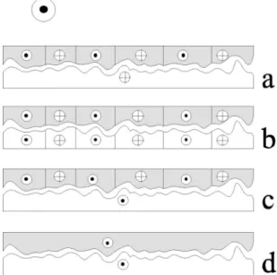
A model of domain structure is sketched in Fig. 6 to ex-plain the main features of the minor TMR curves observed experimentally. It relays on the knowledge of the reversal of the hard magnetic CoOx layer and the strength of the ferro-magnetic coupling between the two electrodes. As described in a previous section, when H, directed along HA in the
direction opposite to the positive saturating field, has values around⫺Hc(CoOx)共in the case of the present MTJ between
⫺85 Oe and ⫺160 Oe兲 a domain structure exists in the
CoOx electrode while the soft Co layer is saturated in the negative field direction. This domain structure consists of regions with main magnetization oriented in the negative field direction created when兩H兩 exceeds 85 Oe which coex-ist with regions with main magnetization oriented in the positive field direction 关Fig. 6共a兲兴. As mentioned above, in-creasing the negative applied field increases the density of reversed magnetized regions until negative domain satura-tion is reached at兩H兩 around 160 Oe.
FIG. 3. Complete (⫺) and minor (⫺䊊⫺) tunnel magnetoresis-tance loops measured on a Co共10 nm兲/Al共1.8 nm, ox 1 mn兲/Co
共10 nm, ox 1 mn兲 tunnel junction with 200 m lateral size. By
reversing the negative applied field at some Hrevon the minor loop, three jumps with different signs appear at some fields H1, H2, and H3.
FIG. 4. Variation of the amplitude of the resistance jumps mea-sured for an applied field Hc(Co)(䊉), H1(䊐), and H2共filled black square兲 as a function of the reversing negative applied field Hrev. The last curve (䊊) is a plot of the sum of the absolute value of the resistance jumps at H1and H2.
FIG. 5. Comparison between a minor tunnel magnetoresistance loop (⫺䊉⫺) and a minor magnetization loop measured by longi-tudinal Kerr effect directly on a Co共10 nm兲/Al共1.8 nm, ox 1 mn 30 s兲/Co共10 nm, ox 1 mn兲 tunnel junction with 200 m lateral size (⫺䊊⫺). The reduction of resistance for applied fields between 22 and 34 Oe is correlated to the appearance of a plateau in the minor magnetization loop. This plateau disappears on the complete mag-netization loop as exemplified in Fig. 2.
As H is reversed from Hrev towards the positive fields,
regions of the soft layer which are located over domains in the CoOx layer with main magnetization oriented in the posi-tive field direction experience a local field equal to H⫹Hf,
where Hf represents the ferromagnetic field coupling
be-tween the two electrodes. Therefore, these regions will rotate first for an applied field of approximately Hcint(Co)⫺Hf. In
fact, the reversal field is slightly higher due to the energy needed to include domain walls in the soft Co layer. After reversal and as exemplified in Fig. 6共b兲, the two magnetic electrodes hold the same domain structure. A part from the magnetization inside the walls, locally in both layers, mag-netizations are parallel. Therefore, the junction resistance de-creases with a jump of⌬R(H1) and is nearly minimal. This
correlated domain structure can be observed in these samples because the energy spend to create domain walls is less than the gain in energy linked to regions ferromagnetically aligned. A further increase of H leads to the reversal of re-gions of the soft layer which are located over domains in the CoOx layer with main magnetization oriented in the negative field direction and experience a local field equal to H⫺Hf.
Indeed, these regions will switch for an applied field of ap-proximately Hcint(Co)⫹Hf. In fact, the reversal field is slightly smaller due to the gain in energy arising from the disappearance of walls in the Co layer. After reversal and as exemplified in Fig. 6共c兲, the soft layer is in a single domain
state while the domain structure remains in the hard layer. Locally in both layers, magnetizations are either parallel or antiparallel and this last magnetic configuration contributes to the increase of the junction resistance⌬R(H2). A further increase of H leads finally to the saturation of the CoOx magnetization关Fig. 6共d兲兴. Here again, locally in both layers, magnetizations are parallel and walls have disappeared. Therefore, resistance decreases and reaches its value at satu-ration. The magnitude of this last resistance jump⌬R(H3) is
close to the difference R„Hc(Co)…⫺R(Hrev), where
R„Hc(Co)… and R(Hrev) are the resistances measured at
Hc(Co) and Hrev, respectively, indicating that the domain
structure present in the CoOx layer remains approximately constant when the applied magnetic field increases from Hrev up to H3.
In the light of this model, the behavior of⌬R(Hi) (i⫽1,
2 and 3兲 as a function of Hrev can be explained. As men-tioned above, when Hrevis between⫺85 and ⫺160 Oe and
when its value decreases, the density of reversed magnetized regions increases in the CoOx electrode. Therefore, R(Hrev)
decreases and consequently ⌬R(H1) also decreases. The
gain in resistance at H2is directly proportional to the density
of domains in the CoOx layer with negative main magneti-zation. By increasing兩Hrev兩, their density increases and
con-sequently ⌬R(H2) decreases too. Finally, increasing 兩Hrev兩
up to 160 Oe, H1 and H2 get close to Hc(Co) and H3 gets
close to Hc(CoOx).
VI. CONCLUSIONS
In this paper, we present results on the magnetic proper-ties of Co and CoOx electrodes and on the magnetotransport properties of Co共10 nm兲/AlOx/CoOx共10 nm兲 tunnel junc-tions. We have demonstrated that the oxidation of the Co electrode leads to a drastic change of its reversal mechanism and to the appearance of a ripple domain structure which induces an increase of the coercive field. When a junction is constituted with these two electrodes separated by an AlOx layer, a dipolar interaction takes place leading to a decrease of the difference between both coercive fields. The main pur-pose of this paper is to report, for the first time, on induced domain structure in the soft magnetic layer duplicated from the hard magnetic layer template by a ferromagnetic type coupling. Then, we characterized magnetotransport proper-ties of these junctions in order to study the magnetization reversal of the soft Co electrode. In fact, spin dependent tunneling current is severely affected by local magnetization fluctuations and the knowledge of the magnetic structure in one electrode共the hard electrode兲 must conduct to the under-standing on the magnetization reversal of the second elec-trode共the soft electrode兲.
ACKNOWLEDGMENTS
The authors thank J.-F. Bobo, M. Demand, J. Latriche, L. Moreau, J.-G. Mussot, and C. Senet for their technical sup-port, and C. Bellouard, G. Marchal, A. Schuhl, and R. L. Stamps for many fruitful discussions and for help with the experiments.
FIG. 6. Sketch showing the evolution of the domain structure in each magnetic layer, the soft Co layer共bottom layer, white兲 and the hard CoOx layer 共top layer, gray scale兲. The symbols 䉺 and 丢 represent the main magnetization in each domain共oriented perpen-dicular to the paper sheet兲 respectively opposite and along the posi-tive saturating field共represented by the big 䉺 outside the sketch兲. After a positive saturation, the applied field is decreased and re-versed until Hrevis reached. At this field, the soft Co layer is satu-rated and a domain structure remains in the hard CoOx layer共a兲. Reversing the field in the positive direction, the reversal of the soft Co layer occurs in two steps. First, the magnetization of regions located under domains in the hard CoOx layer with magnetization oriented in the positive saturating field direction reverses at a field
H1 共b兲. Then, at H2, the Co layer reaches its positive saturation state 共c兲. Finally, the CoOx layer saturates at H3 for which the resistance is minimal共d兲.
1C.H. Shang, J. Nowak, R. Jansen, and J.S. Moodera, Phys. Rev. B
58, R2917共1998兲.
2R. Jansen and J.S. Moodera, J. Appl. Phys. 83, 6682共1998兲. 3
F. Bardou, Europhys. Lett. 39, 239共1997兲.
4V. Da Costa, F. Bardou, C. Bal, Y. Henry, J.-P. Bucher, and K. Ounadjela, J. Appl. Phys. 83, 6703共1998兲.
5R.C. Sousa, J.J. Sun, V. Soares, P.P. Freitas, A. Kling, M.F. da Silva, and J.C. Soares, Appl. Phys. Lett. 73, 3288共1998兲. 6J.S. Moodera, E.F. Gallagher, K. Robinson, and J. Nowak, Appl.
Phys. Lett. 70, 3050共1997兲.
7M. Jullie`re, Phys. Lett. 54A, 225共1975兲.
8C.L. Platt, B. Dieny, and A.E. Berkowitz, J. Appl. Phys. 81, 5523
共1997兲.
9R.E. Dunin-Borkowski, M.R. McCartney, D.J. Smith, S. Gider, B.U. Runge, and S.S. Parkin, J. Appl. Phys. 85, 4815共1999兲. 10C. Tiusan, T. Dimopoulos, M. Hehn, V. Da Costa, Y. Henry, H.
A. M. van den Berg, and K. Ounadjela, Phys. Rev. B 61, 580
共2000兲.
11Ch. Fe´ry, L. Hennet, O. Lenoble, M. Piecuch, E. Snoeck, and J.F. Bobo, J. Phys.: Condens. Matter 10, 6629共1998兲.
12This increase in H
ccannot be explained only by the reduction of
the magnetic effective layer thickness. Indeed, even if an in-crease of 50% in Hc is observed as the thickness of a
nonoxi-dized Co layer is decreased from 10 to 5 nm, another mechanism must be invoked. Therefore, we have studied the magnetic sus-ceptibility of the CoOx layer as a function of temperature. The Ne´el and blocking temperatures of this thin layer appear to be below 80 K. So, at room temperature, an eventual antiferromag-netic CoOx layer cannot be called to explain the Hc increase.
13K.D. Leaver, Thin Solid Films 2, 149共1968兲. 14
C. Tiusan and M. Hehn共private communication兲. 15
M. Hehn, O. Lenoble, D. Lacour, A. Schuhl, C. Tiusan and K. Ounadjela共unpublished兲.
16D.V. Berkov and N.L. Gorn, Phys. Rev. B 57, 14 332共1998兲. 17L. Ne´el, C. R. Acad. Sci. URSS 255, 1676共1962兲.
18In this article, the TMR signal is defined as the ratio of the dif-ference of resistance in the parallel and antiparallel magnetiza-tion configuramagnetiza-tions and the resistance in the antiparallel magne-tization configuration.
19W.F. Brinkman, R.C. Dynes, and J.M. Rowell, J. Appl. Phys. 41, 1915共1971兲.