HAL Id: hal-01989533
https://hal.uca.fr/hal-01989533
Submitted on 22 Jan 2019
HAL is a multi-disciplinary open access
archive for the deposit and dissemination of
sci-entific research documents, whether they are
pub-lished or not. The documents may come from
teaching and research institutions in France or
abroad, or from public or private research centers.
L’archive ouverte pluridisciplinaire HAL, est
destinée au dépôt et à la diffusion de documents
scientifiques de niveau recherche, publiés ou non,
émanant des établissements d’enseignement et de
recherche français ou étrangers, des laboratoires
publics ou privés.
Gateway Selection for Downlink Communication in
LoRaWAN
Samira Abboud, Nancy El Rachkidy, Alexandre Guitton, Haidar Safa
To cite this version:
Samira Abboud, Nancy El Rachkidy, Alexandre Guitton, Haidar Safa. Gateway Selection for Downlink
Communication in LoRaWAN. IEEE WCNC 2019 (IEEE Wireless Communications and Networking
Conference 2019), Apr 2019, Marrakech, Morocco. �hal-01989533�
Gateway Selection for Downlink Communication in
LoRaWAN
S
AMIRAA
BBOUD(1, 2), N
ANCYE
LR
ACHKIDY(1), A
LEXANDREG
UITTON(1), H
AIDARS
AFA(2)(1) Universit´e Clermont Auvergne, CNRS, LIMOS, F-63000 Clermont-Ferrand, France (2) American University of Beirut
[email protected], nancy.el [email protected], [email protected], [email protected]
Abstract—The Long Range Wide Area Network (LoRaWAN) standard was mainly developed to meet the requirements of many emerging Internet of Things (IoT) applications as it provides low power and low cost connectivity over long distances. In LoRaWAN, when an end-device transmits an uplink message, gateways that receive this message transmit it to the network server, which, in turn, selects a single gateway to reply to the end-device. LoRaWAN does not specify how to select the gateway. In this paper, we focus on the gateway selection for downlink communications in LoRaWAN in order to improve the throughput of the network. We aim to present and evaluate several algorithms for selecting the best gateway for downlink while increasing LoRaWAN throughput for different types of gateway deployment. We show that the system throughput depends on this deployment and that balancing the number of end-devices per gateway improves the performance compared to choosing the gateway with the highest signal quality.
I. INTRODUCTION
Low-Power Wide Area Networks (LPWANs) are based on long-range communications with low-power consumption at a low cost. LPWANs are suitable for several Internet of Things (IoT) applications such as smart cities, smart homes, smart parking, smart buildings, transport, industry, agriculture, consumers electronics [1], [2], leak detection or environment monitoring [3], city wide meter reading collection [4]. One of the main LPWAN technologies is LoRaWAN [5] (Long Range Wide Area Network), which is an open-standard.
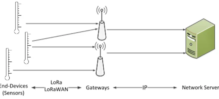
In LoRaWAN, end-devices send data to the network server through gateways as shown in Fig. 1: end-devices and gate-ways communicate using LoRa while gategate-ways and the net-work server communicate over an IP netnet-work. LoRaWAN en-ables uplink communications from end-device to the network server, and downlink communications from the network server to the end-device.
When an end-device transmits an uplink message, all gate-ways that receive this message transmit it to the network server which removes duplicates. When the network server has a frame to send to an end-device, it selects a single gateway to relay this frame. However, LoRaWAN does not specify how to select the gateway.
In this paper, we focus on the gateway selection for down-link communications in LoRaWAN in order to improve the throughput of the network. We aim to present and evaluate several algorithms for selecting the best gateway for downlink communications while increasing LoRaWAN throughput for different types of gateway deployment. Our contributions are
End-Devices
(Sensors) Gateways IP Network Server LoRa
LoRaWAN
Fig. 1. In LoRaWAN architecture, end-devices communicate to the network server through gateways.
three-fold. First, we study three types of gateway deployment and we show that the system throughput depends on this deployment. Second, we show that balancing the number of end-devices per gateway (also known as load) improves the performance compared to choosing the gateway with the highest signal quality. Third, we show that combining load and signal quality does not further improve the throughput.
The rest of the paper is organized as follows. Section II describes LoRaWAN and presents some related work. Sec-tion III illustrates three scenarios for gateway deployment and describes three gateway selection algorithms. Section IV analyzes our simulation results. Finally, Sect. V concludes this paper.
II. STATEOFTHEART
In the following, we first describe the media access control (MAC) protocol LoRaWAN, and then we present some of the related work.
A. The LoRaWAN protocol
LoRaWAN is an open standard protocol which defines the MAC layer for LPWAN technology. LoRaWAN is designed by the LoRa Alliance [6] on top of LoRa, which is a proprietary wireless physical layer developed by Semtech [7].
LoRaWAN enables three classes of operation for devices: class A, class B, and class C. In class A, end-devices send data based on ALOHA mechanism and wait for a reply from the network server. Then, they switch to sleep mode to save energy until the next transmission. In class
B, which is optional, end-devices have additional scheduled receive periods to allow downlink communications with a bounded delay. In class C, which is also optional, end-devices are always active.
LoRaWAN specifies how the end-devices connect to LoRa gateways using unlicensed radio spectrum in the Sub-GHz Industrial, Scientific and Medical (ISM) bands. The gateways are then connected to the network server through an IP network. End-devices shall apply restricted transmissions in accordance with the requirements of the ISM band. For this, channels are grouped into sub-bands. When an end-device transmits a frame on a band, it can not reuse this sub-band before Tof f = Tair(dc1 − 1) seconds, where Tair is the
time on air or the frame transmission time and dc is the duty cycle for the sub-band (usually dc < 1%).
In this paper, we concentrate on downlink communications in class A. The details of class A are as follows. After each transmission, the end-device opens two receive windows RX1 and RX2 during which the end-device listens for possible downlink traffic. RX1 is opened one second after the end of the transmission. By default, RX1 uses the same frequency channel and data rate (DR) as the transmission. RX2 is opened two seconds after the end of the transmission when the end-device did not receive a frame during RX1. RX2 uses a fixed frequency and data rate. For Europe, the default parameters are 869.525 MHz with DR0 [5]. In class A, downlink traffic can not be transmitted until a successful uplink transmission is decoded by the gateway.
The data rate translates into the LoRa spreading factor (SF), which ranges from SF7 to SF12 and denotes the number of chirps used to encode a symbol. SF provides a tradeoff between data rate and range. The lower the SF, the higher the data rate but the lower the immunity to interference thus the smaller the range.
B. Related Work
The performance, features and limits of LoRaWAN based networks have been studied in many recent papers [3],[8], [9], [4], [10], [11].
An overview of LoRaWAN capabilities and limitations was provided in [3]. This overview matches LoRaWAN capabilities to application use cases. A LoRaWAN deployment must be carefully dimensioned to meet the requirements of each use case. Thus, the combination of the number of end-devices, the selected SFs and the number of channels determine if the LoRaWAN ALOHA based access and the maximum duty-cycle regulation fit each use case. For instance, it was observed that deterministic monitoring, such as industrial automation, critical infrastructure monitoring and actuation, require real time operation, and therefore cannot be guaranteed with cur-rent LoRaWAN state of the art.
The coverage of LPWANs and especially LoRa was studied in [8], where experiments have been conducted in Finland. The measurements were executed for cases when an end-device located on ground or on water sends data to a single base
station. Results show that the maximum communication range is over 15 km on ground and close to 30 km on water.
The usage of LoRa in indoor environments was studied in [9]. Measurements were conducted in the main campus of the University of Oulu, Finland. Results indicate that with the largest spreading factor of 12 and 14 dBm transmit power, the whole campus area can be covered by a single base station. The average measured packet success delivery ratio for this case was 96.7%, even with no acknowledgements and retransmissions used. The campus was covered also with lower spreading factors with 2 dBm transmit power, but considerably more packets were lost.
Many experiments were conducted in [4] to estimate the in-fluence of concurrent transmissions. Authors demonstrate how concurrent non-destructive transmissions and carrier detection can be employed. Their deployment experiment demonstrates that 6 LoRa nodes can form a network covering 1.5 ha in a built-up environment, achieving a potential life-time of 2 year on 2 AA batteries and delivering data within 5 s and reliability of 80%. Moreover, a new MAC protocol, LoRaBlink, was developed to enable direct connection of end-devices without using LoRaWAN.
Researchers have identified that the gateway selection is an important issue in LoRaWAN. Both [10] and [11] state that the network server needs to select the best gateway among all candidates when replying in donwlink communications to each end-device. To the best of our knowledge, there is no relevant work that provides information on this selection, nor studies the impact of this selection on LoRaWAN throughput.
III. PROPOSITIONS
In this section, we present our contributions. First, we classify the gateway deployments into three scenarios. Then, we study the existing algorithms for gateway selection.
A. Scenarios of gateway deployment
In this subsection, we classify the gateway deployment into three scenarios: urban scenario, environmental scenario, and hybrid scenario. To do this, we consider a 2-dimensional space where end-devices and gateways are deployed.
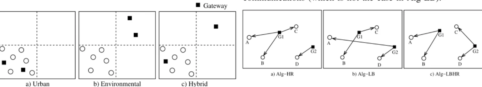
Urban scenario is mostly used for monitoring applica-tions such as smart cities with smart parkings and smart buildings [1], [2]. In this deployment, all end-devices are in communication range with all gateways. Figure 2.a) shows an example of urban deployment covering a city divided into four quarters. In this example, all devices are deployed in the bottom-left quarter.
Environmental scenario is moslty used for monitoring ap-plications such as volcanos, forests, and lakes [3]. In this deployment, end-devices are deployed in the critical zone and send data to gateways that are localized far away from the monitoring area. Figure 2.b) shows an example of environmen-tal deployment on a volcano. In this example, we consider that end-devices are covering a part of the volcano which is located in the bottom-left quarter of the figure. However, gateways
are deployed in a distant city which is located in the top-right quarter of the same figure. We refer to this scenario as ENV. Hybrid scenario can be used for the same monitoring applications as in urban and environmental scenarios. In this deployment, end-devices are not equidistant from the gate-ways. Indeed, Fig. 2.c) shows that one gateway is in the vicinity of all end-devices, and that the remaining gateways are further away from these end-devices.
End−device Gateway
a) Urban b) Environmental c) Hybrid
Fig. 2. Example of the three scenarios of gateway deployment.
B. Algorithms for gateway selection
In this subsection, we identify three classes of algorithms that the network server might use in order to select the suitable gateway for each end-device in downlink communications.
The first algorithm is based on the received signal strength indicator (RSSI). The goal of this algorithm is to increase the link quality and the throughput. In the following, we refer to this algorithm as Alg-HR. Using Alg-HR, the network server selects, among all gateways that are in communication range with an end-device, the gateway receiving frames from the end-device with the highest RSSI. Figure 3.a) shows an example of Alg-HR selection. In this example, we consider four devices and two gateways. We assume that all end-devices are in communication range with both gateways. As end-devices A, B, and C are closer to gateway G1 than to gateway G2, the network server selects G1 to communicate with end-devices A, B, and C. End-device D is closer to G2 than to G1. Thus, the network server selects G2 to communicate with D.
The second algorithm balances the number of end-devices per gateway. The goal of this algorithm is to reduce the load of a gateway, and to balance the number of ACKs that can be sent by this gateway. In the following, we refer to this algorithm as Alg-LB. Using Alg-LB, the network server selects, among all gateways that are in communication range with an end-device, the gateway with the lowest load (i.e the lowest number of end-devices), in order to communicate with this end-device. Figure 3.b) shows an example of Alg-LB selection. In this example, G1 and G2 have the same load. End-devices A and D are thus connected to G2 while end-devices B and C are connected to G1.
The third algorithm is a combination of HR and Alg-LB. In the following, we refer to this algorithm as Alg-LBHR. Using Alg-LBHR, the network server selects a gateway among all gateways that are in communication range with an end-device. The selected gateway is a gateway that has not reached
the maximum load yet. If there are several such gateways, the one with the highest RSSI is selected. Figure 3.c) shows an example of Alg-LBHR. In this example, G1 and G2 have the same load as in Fig. 3.b). However, the assignment of gateways for each end-device is different as the selection is also based on the RSSI with each end-device. Thus, each gateway might have the same number of end-devices and the end-devices are closer to the gateway from which they have downlink communications (which is not the case in Alg-LB).
D B D
a) Alg−HR b) Alg−LB c) Alg−LBHR G2 G1 G2 G2 G1 C G1 C C A A B B D A
Fig. 3. Example of the gateway selection algorithms.
IV. SIMULATIONS AND RESULTS
In this section, we study the performance of gateway selection on the different scenarios of gateway deployment.
A. Parameter settings and guidelines
Simulations are carried out using our own simulator de-veloped in JAVA and following the LoRaWAN specification [5]. We consider that transmissions for all SFs and channels are orthogonal, and that uplink and downlink transmissions do not interfere with each other. We consider the capture effect conditions where a frame is decoded if the received signal is > 6dB than the sum of all interferers. We consider the following: for urban scenario, end-devices and gateways are deployed in an area size of 2 ∗ 2km2. For ENV scenario, end-devices are deployed in an area size of 2 ∗ 2km2, and gateways are deployed in an area size of 2∗2km2but which is distant from the area of the end-devices. For hybrid scenario, end-devices and one gateway are deployed in an area size of 2 ∗ 2km2, and the remaining gateways are deployed in a distant area of 2 ∗ 2km2(Fig. 2.). We computed the number of collided frames in uplink communications, the load per gate-way and the number of received acknowledgments (ACKs) for confirmed frames in downlink communications. Afterwards, the throughput and the network capacity of LoRaWAN are analyzed and discussed based on the obtained results. We set some parameters and followed some guidelines as listed below. 1) For the gateway deployment, we consider a network composed of g gateways with N end-devices. The maximum communication range between end-devices and gateways is about R = 4 km. We ensure that each end-device is in communication range with at least one gateway.
2) The RSSI for an end-device is measured using the Hata-Okumura [12], [13] propagation model for medium-sized cities, with a default transmission power of 14 dBm.
3) We only use the three mandatory 125-kHz chan-nels from the 868-MHz band for data communica-tions in LoRaWAN. The channel used by each end-device is randomly chosen from the following set {868.1, 868.3, 868.5} and the duty cycle of 1% is re-spected.
Simulation results are obtained by averaging over ten thousand samples.
B. Collision behavior and interference measurements When two LoRa transmissions overlap at the receiver, several conditions determine whether the receiver can decode the frames. These conditions depend on channel, spreading factor (SF), power and timing. As LoRa is a form of frequency modulation, it presents the capture effect that occurs when two signals are present at the receiver and the weaker signal is suppressed by the stronger one. Therefore, frame x collides with frame y when Px− Py < PT hreshold [14], where Px
is the received signal strength of transmission x, Py is the
received signal strength of transmission y, and PT hreshold is
the power threshold equal to 6 dB.
We analyze the results of the simulations based on the model described previously. Figure 4 shows the number of transmit-ted and collided frames per second for uplink communications with g = 4 gateways in terms of the number of end-devices in the network. Obviously, the number of transmitted and collided frames increases with the increase of the number of end-devices . In this figure, the percentage of collided frames increases from 5% with 50 devices to 15% with 150 end-devices. Therefore, adding more end-devices greatly increases the collision probability.
0 2 4 6 8 10 12 50 100 150 Number of f rames per second Number of end-devices TransmittedFrames CollidedFrames
Fig. 4. Number of transmitted and collided frames per second for uplink communications increases with the size of the network.
C. Gateway load for downlink communications
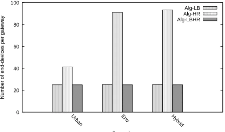
Figure 5 shows the average load per gateway for each algorithm in each scenario. We used g = 4 gateways and N = 100 end-devices. We observe that in Alg-HR, the average load per gateway is greater than that in LB and Alg-LBHR. This is because in Alg-LB and Alg-LBHR, the load is distributed almost equally between the gateways (i.e we are
balancing the load between gateways), which is not the case in Alg-HR. Furthermore, we observe that in ENV and hybrid scenarios, the gateway load for Alg-HR is greater than that in urban scenario. This is due to the gateway deployment, since in ENV and hybrid scenarios, one gateway is closer to the end-devices than the other gateways, which yields a high load compared to other gateways.
0 20 40 60 80 100 Urban Env Hybrid Number of end-devices per gat eway Scenario Alg-LB Alg-HR Alg-LBHR
Fig. 5. Average load per gateway with g = 4 gateways and N = 100 end-devices in downlink communications.
D. Confirmed Throughput
If no collision occurs for an uplink, the frame is acknowl-edged by the gateway. After each uplink frame transmission, the end-device waits for an ACK from a gateway. For class A end-devices, LoRaWAN acknowledgments can be received either during RX1 or RX2.
More simulations were run to study the throughput by extending the previously described simulations to incorporate frame confirmations. We assume the confirmation is a message without a payload that has the ACK bit set to 1 and a length of 1 byte (short frame). We consider the following model of class A: after the reception of a frame, the gateway tries to send an ACK in RX1. If RX1 is busy, the gateway tries to send an ACK in RX2. If RX2 is also busy, the ACK is not sent. Then we compare the number of received acknowledged frames (i.e the ACK frames) in each of the three aforementioned algorithms for the three scenarios1 .
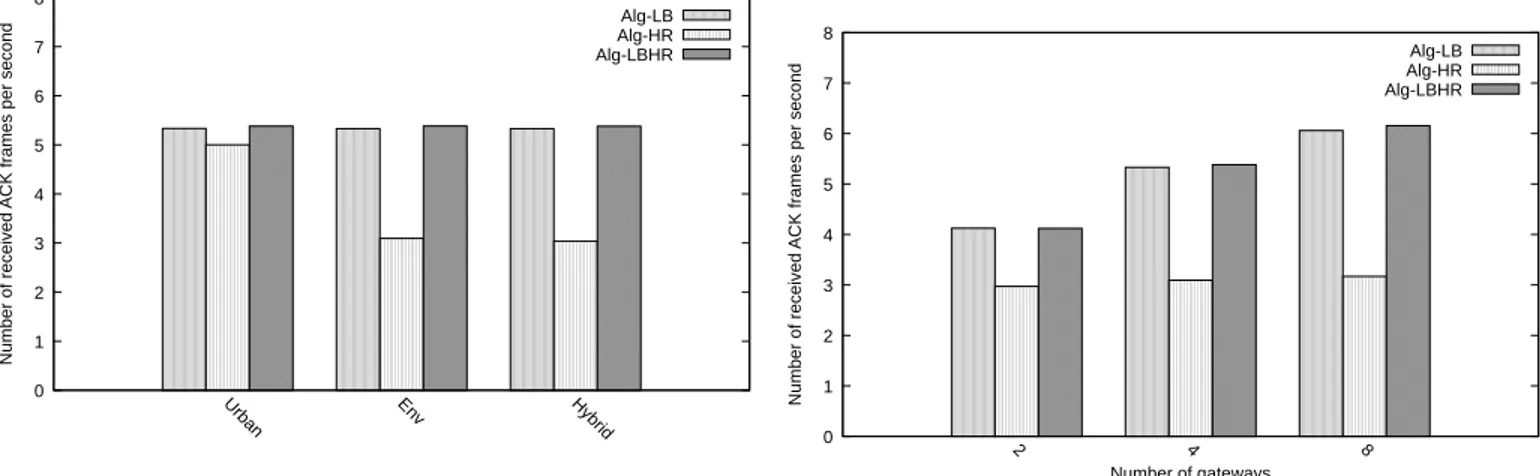
Figure 6 depicts the number of received ACKs for confirmed uplink with g = 4 gateways and N = 100 end-devices. We observe that the Alg-HR is the worst compared to Alg-LB and Alg-LBHR. This is due to the largest load per gateway in Alg-HR (Fig.5). Indeed, when the load per gateway increases, the number of received ACKs decreases as collisions increase. Additionally, we observe that the throughput is almost the same in Alg-LB and Alg-LBHR. Hence, we found that com-bining both the load and the signal quality (as for Alg-LBHR), does not improve further the throughput. For example, results show that for urban scenario, 84.1% of the frames have been acknowledged by the gateway in Alg-LB, compared to 78.9%
in Alg-HR; for ENV scenario, 84.1% of the frames have been acknowledged by the gateway in Alg-LB, compared to 48.9% in Alg-HR; and finally for hybrid scenario, 84.1% of the frames have been acknowledged by the gateway in Alg-LB, compared to 48% in Alg-HR. 0 1 2 3 4 5 6 7 8 Urban Env Hybrid Number of received A CK f rames per second Alg-LB Alg-HR Alg-LBHR
Fig. 6. Number of received ACK frames with N = 100 end-devices and g = 4 gateways for the three algorithms in each scenario.
Figure 7 shows the number of received ACK frames per second in terms of the number of end-devices for the ENV sce-nario. We notice that the number of received ACKs decreases with the increase in the number of end-devices. This is due to the fact that the number of collisions in uplink communications increases, leading to a decrease in the number of successful frames, and hence to a decrease in the network throughput. Therefore, we notice that LoRaWAN does not scale with the number of end-devices. For example, results show that in Alg-LB 90% of the ACKs were received with 50 end-devices, while 64% of the ACKs were received with 150 end-devices.
0 2 4 6 8 10 50 100 150 Number of received A CK f rames per second Number of end-devices Alg-LB Alg-HR Alg-LBHR
Fig. 7. Number of received ACK frames according to the number of end-devices with g = 4 gateways for ENV scenario.
Figure 8 shows the number of received ACK frames per second in terms of the number of gateways for the ENV sce-nario. We observe that the number of received ACKs increases significantly for both Alg-LB and Alg-LBHR, while it remains almost the same for Alg-HR. This is due to the fact that in
Alg-LB and Alg-LBHR, the load per gateway decreases when increasing the number of gateways in the network, leading to an increase in the number of received ACKs. Results show that the increase in the number of gateways clearly improves the throughput which reaches, when using 8 gateways, a gain of 45% for Alg-LB and Alg-LBHR compared to Alg-HR.
0 1 2 3 4 5 6 7 8 2 4 8 Number of received A CK f rames per second Number of gateways Alg-LB Alg-HR Alg-LBHR
Fig. 8. Number of received ACK frames according to the number of gateways with N = 100 end-devices for ENV scenario.
V. CONCLUSION
In this paper, we presented and evaluated three algorithms for selecting the best gateway for downlink communications while increasing LoRaWAN throughput for three types of gateway deployment. First, we show that the system through-put depends on this deployment. For instance, ENV and hybrid scenarios have the worst throughput compared to urban scenario. Second, we show that balancing the load per gateway improves the performance compared to the increase in the signal quality. Finally, we show that combining both the load and the signal quality does not improve further the throughput. Furthermore, we studied the number of frame collisions and ACK receptions that might arise under heavy load of end-devices, and explored the impact of the number of gateways on LoRaWAN network. In order to maximize the utilization of LoRaWAN while increasing the throughput, parameters like the number of end-devices, the number of gateways, the sce-nario of gateway deployment, and the algorithm for gateway selection should be known in advance. Thus, the combination of these four parameters determines the LoRaWAN throughput for downlink communications. In our future work, we aim to propose an optimal algorithm based on ILP, and a heuristic based on our analyses in order to find the optimal gateway placement.
REFERENCES
[1] Bouleogeorgos, Alexandros-Apostolos A and Diamantoulakis, Panagi-otis D and Karagiannidis, George K, “Low power wide area networks (LPWANs) for internet of things (IoT) applications: Research challenges and future trends,” arXiv preprint arXiv:1611.07449, 2016.
[2] U. Noreen, A. Bounceur, and L. Clavier, “A study of LoRa low power and wide area network technology,” in Advanced Technologies for Signal and Image Processing (ATSIP), 2017 International Conference on, pp. 1–6, IEEE, 2017.
[3] F. Adelantado, X. Vilajosana, P. Tuset-Peiro, B. Martinez, J. Melia-Segui, and T. Watteyne, “Understanding the limits of LoRaWAN,” IEEE Communications Magazine, vol. 55, no. 9, pp. 34–40, 2017.
[4] M. Bor, J. E. Vidler, and U. Roedig, “LoRa for the internet of things,” 2016.
[5] N. Sornin, M. Luis, T. Eirich, T. Kramp, and O. Hersent, “LoRaWAN Specification,” Standard V1.0, LoRa Alliance, 2015.
[6] LoRa alliance. https://www.lora-alliance.org/.
[7] Semtech, “LoRa Modem Design Guide, rev.1,” July 2013.
[8] J. Petajajarvi, K. Mikhaylov, A. Roivainen, T. Hanninen, and M. Pet-tissalo, “On the coverage of LPWANs: range evaluation and channel attenuation model for LoRa technology,” in ITS Telecommunications (ITST), 2015 14th International Conference on, pp. 55–59, IEEE, 2015. [9] J. Pet¨aj¨aj¨arvi, K. Mikhaylov, M. H¨am¨al¨ainen, and J. Iinatti, “Evaluation of LoRa LPWAN technology for remote health and wellbeing monitor-ing,” in Medical Information and Communication Technology (ISMICT), 2016 10th International Symposium on, pp. 1–5, IEEE, 2016. [10] A. Augustin, J. Yi, T. Clausen, and W. M. Townsley, “A study of LoRa:
Long range & low power networks for the internet of things,” Sensors, vol. 16, no. 9, p. 1466, 2016.
[11] J. So, D. Kim, H. Kim, H. Lee, and S. Park, “Loracloud: LoRa platform on openstack,” in NetSoft Conference and Workshops (NetSoft), 2016 IEEE, pp. 431–434, IEEE, 2016.
[12] Y. Okumura, “Field strength and its variability in vhf and uhf land-mobile radio service,” Rev. Electr. Commun. Lab., vol. 16, pp. 825–873, 1968.
[13] M. Hata, “Empirical formula for propagation loss in land mobile radio services,” IEEE transactions on Vehicular Technology, vol. 29, no. 3, pp. 317–325, 1980.
[14] M. C. Bor, U. Roedig, T. Voigt, and J. M. Alonso, “Do LoRa low-power wide-area networks scale?,” in Proceedings of the 19th ACM International Conference on Modeling, Analysis and Simulation of Wireless and Mobile Systems, pp. 59–67, ACM, 2016.