ISSN: 2602-3199
- This is an Open Access article distributed under the terms of the Creative Commons Attribution-Noncommercial 4.0 Unported License, permitting all non-commercial use, distribution, and reproduction in any medium, provided the original work is properly cited.
- Selection and peer-review under responsibility of the Organizing Committee of the Conference
The Eurasia Proceedings of Science, Technology, Engineering & Mathematics (EPSTEM), 2018
Volume 4, Pages 35-42
IConTES 2018: International Conference on Technology, Engineering and Science
Numerical Analysis of the Behavior of Structures Damaged by Fatigue and
Repaired by Composite Patch
Habib ACHACHE
Oran2 Mohamed Ben Ahmed University
Djaafar AITKACI Djilali Liabes University Abdelmajid MOULGADA
Ibn-Khaldoun University
Abstract
: In this paper, a numerical study of the behavior of fatigue cracks of damaged composite repaired aeronautical structures was presented. Various parameters have been highlighted such as effect of the dimensions and mechanical properties of the patch as well as the orientation of the fibers and the effect of the dimensions and mechanical properties of the adhesive. Two geometrical models have been proposed in order to see the influence of the crack position and the overall failure behavior under fatigue stress of the damaged structure. The results on the different geometric models of cracked plates and fissure plates from nicks show that composite patch repair is an effective technique for increasing plate strength, decreasing stress concentration and prolonging their service life.Keywords: Composite patch, Fatigue, Fiber orientation, Life time and propagation
Introduction
Patch repair is a very effective method used to strengthen or repair damaged structures. This technique has had wide use in the aeronautical sector, especially military aircraft. In addition to environmental conditions, aeronautical structures are exposed to cyclic loadings over time during their service life, from which the control and maintenance of these structures becomes indispensable.
Composite materials in advanced engineering structures have gained great popularity over the past decades because of their high strength/weight ratios and high damping capacity (Içten et al. 2002). The use of composite materials to repair damaged structures has evolved rapidly in different fields. Compared to mechanically fastened joints, adhesively bonded joints have many advantages such as load distribution over larger area due to absence of holes, no damage to composite material due to hole machining, no increment of weight due to the fasteners weight and no stress concentrations due to the presence of holes (Elhannani et al. 2016, Benchiha et al. 2015, 2016). However, stress concentrations always occur at the edge of adhesive layer in adhesively bonded joints (Erdogan et al. 1971, Costa Mattos et al. 2012). Therefore, adhesively bonded joints are more preferable to mechanical joints in joining composite materials (Içten et al. 2002).
Based on the technique, several authors (H. Fekirini et al., 2008 ; B Bachir Bouiadjra et al., 2008) showed that the stress intensity factor for patched crack exhibits an asymptotic behaviour as the crack length increases. This is due to the stress transfer toward the composite patch throughout the adhesive layer. The analysis of the effects of the geometrical properties of the composite on the repair performance was retained great interest in the literature. Heller and Kaye (M. Heller and R. Kaye.,2002) used the genetic algorithm to optimise the patch shape. Kaddouri et al,.2008, Ouinas et al.,2009 , analysed numerically the performance of the octagonal, circular and elliptical shape of the patch. They showed that the patch shape has a significant effect on the value of the stress intensity factor at the crack tip. In addition, the use of appropriate patch shape can reduce the level of the
thermal residual stresses due to the adhesive curing (B. Bachir Bouiadjra et al.,2007) ,analysed the effect of the patch thickness, they showed that the patch thickness must also be optimised. The comparison between the double symmetric patch and the single was analysed by several authors (M. Belhouari et al.,2004; B. Bachir Bouiadjra et al.,2010). All these authors showed that the use of double symmetric patch improves the fatigue life of the repaired structures. This improvement is due to the double stress transfer in the double patch configuration. In addition, the double symmetric patch annuls the bending effect due to the eccentricity of the composite patch in the case of single sided patch. The double symmetric patch has two main disadvantages: the first is the difficulty to follow the crack propagation and the second is the relatively higher levels of the thermal residual stresses because of the double adhesive curing. The objective of this study is to analyze the distribution of the stress intensity factor along the crack front for repaired crack with bonded composite patch. The effect of the thickness of the repaired plate is specially analyzed in order to show the difference of the repair performance for thick and thin plates.
The purpose of this study is to analyze by numerical simulation the fatigue test on damaged structures repaired by composite patch. A notch in an aluminum plate causes high localized stresses near the notch leading to a high stress rate. These constraints can be significantly reduced by the application of a composite repair patch. These stress values will be considered as critical values to ensure the role of each of the repair materials in order to validate the design of the repair part. The constraints on the aluminum plate, the adhesive and the composite patch must be studied individually to establish the strength, longevity and effectiveness of the repair.
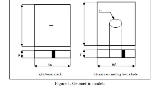
Geometric Models
In our study, two geometric models were chosen to study crack propagation in several positions (figure 1). Numerical modeling of the fatigue test was performed on a 2024-T3 aluminum plate using the Afgrow calculation code. The dimensions of the plate and notch are shown in Table 1.
Figure 1. Geometric models
Table 1. Dimensions of notched and cracked plates H Length [mm] W Width [mm] E Thickness [mm] D Diameter [mm] C
Length of the crack [mm]
200 100 2 10 2
These models are then reinforced by a composite patch whose dimensions vary according to our study.
Properties of the Patch
Stacking Sequence of the Patch
The composite used for the repair is a graphite-epoxy type laminate composed of graphite fibers and an epoxy resin. The laminate consists of 14 plies of a unidirectional composite material or the thickness of each ply is
37
The graphite fiber used here is the HR fiber, belonging to the group of high strength fibers.
Rigidity of the Patch
Calculation of the rigidity of the patch is essential for it to have a good transfer of the load of the damaged plate to the patch. First, we must size this patch for it to be effective. The stiffness ratio, S, between the composite repair patch and the damaged structure should be between 1.0 <S <1.5
For our case, we have a composite graphite / epoxy composed of 14 folds of different orientations, its longitudinal Young's modulus is equal to 110909.843 MPa and a thickness of 1.85 mm, against for the damaged structure the Young's modulus is of 73084.4 MPa and a thickness of 2mm, so we can calculate the stiffness S:
S=
1
.
4
x2
4
.
73084
7x1.85
110909.843
p p r re
E
e
E
Parameters of the Test
For our case, the applied constraints used, such as σmax = 50MPa and σmin = 5MPa, in order to compare the results between an unrepaired and repaired structure. The number of cycles at break as well as the size of the corresponding crack will be calculated using the Nasgro equation.
Analysis and Results
Influence of Patch DimensionsThe geometry of the patch plays an important role in the number of cycles at break. To analyze the effect of the patch size on the failure behavior of a cracked plate and a cracked plaque from a repaired notch, we chose a rectangular patch of different sizes. The results obtained illustrate the influence of patch and adhesive parameters on the service life of damaged and repaired structures.
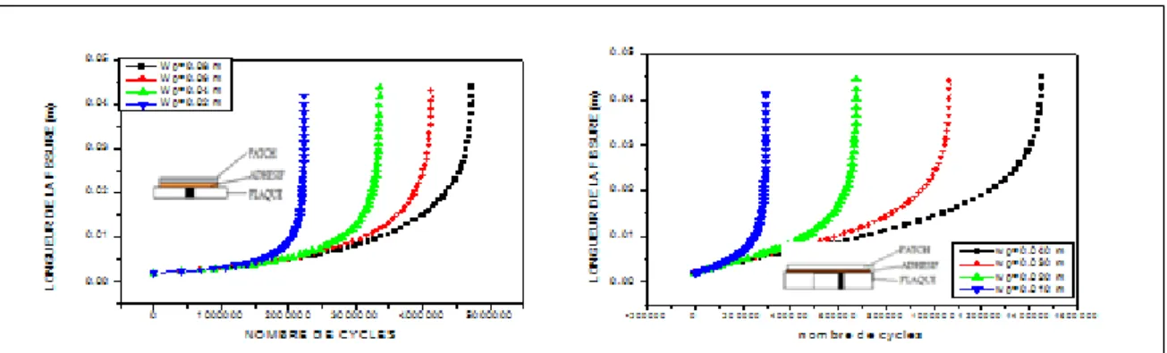
Influence of the Width of the Composite
To study the influence of the width of the patch on the propagation of cracks, we chose a fissured plate and another plate with crack emanating from central circular notch of diameter 10 mm, repaired by patch length Lp = 100mm and width Wp = 100mm.
Figure 2. Evolution of crack length versus number of cycles at break for different patch widths for both geometric models
The width of the composite is an important parameter to size the patch so that it brings more resistance to the damaged structure. If the width of the patch is important plus the overlap section is important so the patch covers more section of the plate, resulting in a considerable reduction of stresses in the damaged area (figure 2). It is therefore better to choose a rather large patch and more important than the length of the crack.
For smaller patches, once the crack exceeds the edge of the patch, the crack spreads rapidly to the free edge of the patch. For both geometric models, it is noted that the percentage of gain in life depends on the width of the patch and the position of the crack. In the presence of a notch, the gain is less considerable in lifetime.
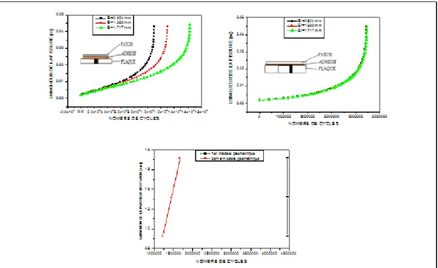
Influence of the Length of the Composite
Figure 3. Influence of the length of the composite
From the two curves in Figure 3, the length of the patch does not have a great influence on the strength of the damaged and repaired structure. Several studies have shown that there is an optimum length from which the increase in length has no influence on the strength and the life of the structure.
Effect of the Thickness of the Patch
The thickness is an important parameter to optimize the patch to bring a high resistance to the damaged structure. The increase in the thickness of the patch causes an increase in the rigidity of the structure.
Figure 4. Effect of patch thickness
From Figure 4, it can be seen that increasing the thickness increases the strength of the repaired structure as well as its life, but it is important to choose a thickness of the patch as thin as possible to ensure a shape. aerodynamic structure; in addition to avoiding a more resistant patch than the plate, this causes a great heterogeneity of the distribution of stresses in the damaged structure which causes a deformation of the plate. The gain in life of the
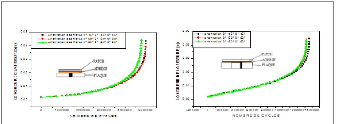
39 Effect of Fiber Orientation
The choice of fiber orientation of the composite is essential to absorb more stress from the plate through the adhesive. In addition, it is inadvisable to choose a patch with the same fiber orientation in all layers because usually the patch will be exposed to normal shear, peel, and stress. Also, the fibers oriented at 0 ° along the axis of loading are efficient in the absorption of the constraints of the plate, that is why we chose the orientation of the first fold: 0 °.
To highlight the effect of fiber orientation of the composite material, we considered three cases. fiber orientation (0 ° 45 ° 0 ° -45 ° 0 ° 45 °), (0 ° 60 ° 0 ° -60 ° 0 ° 60 °), (0 ° 90 ° 0 ° -90 ° 0 ° 90 °) .
Figure 5. Effect of fiber orientation of the patch
It is noted that the choice of fiber orientation is essential to have a long service life of the structure and also a great reduction of the stresses in the damaged plate.
Influence of the Properties of the Adhesive
To see the influence of the parameters of the adhesive on the fatigue strength of the damaged and repaired structures, we chose as a reference the adhesive FM 73 of shear modulus Gxy of 413.685 MPa and a thickness of 0.15 mm
Influence of the Thickness of the Glue (adhesive)
The thickness of the adhesive is the most important geometrical parameter in a bonding of two substrates, tensile tests show for joints with single overlap joints, a very fast growth of the resistance from very thin thickness (0.005 mm <eglue <O.2mm) followed by a decrease which tends to diminish as the thickness becomes important (0.005mm <eglue <O.2mm) more breaks become more and more adhesive when the thickness increases.
Indeed the joint strength increases rapidly for small thicknesses (a few hundredths of a millimeter) passes through an optimum then decreases.
Figure 6. Influence of glue thickness (adhesive)
It can be seen from figure 6 that increasing the thickness of the adhesive considerably reduces the strength of the damaged and repaired structure, since the greater the thickness of the adhesive, the more structural defects such as porosity, micro cavity, crack etc.
On the other hand, the lower the thickness of the adhesive is the load transfer from the plate to the patch, so it is best to optimize the thickness of the adhesive.
It is also noted that the number of cycles at break is inversely proportional to the thickness of the adhesive. The percentage of life loss of the structure depends on the thickness of the adhesive and the position of the crack (geometric model).
It is noted that the life of the plates increases as the thickness of the adhesive decreases.
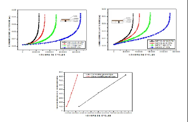
Influence of the Shear Modulus of the Adhesive
A study has shown that a good adhesive is characterized by its low shear modulus, this allows the reduction of the tensions transmitted to the adhesive. In the case of repaired cracks, the objective is to transfer the maximum of stresses to the adhesive and consequently to the patch in order to reduce the energy at crack point. Theoretically, it is preferable to use adhesives with a high shear modulus (poor adhesive quality) for the repair of cracks and defects.
To verify this behavior, we studied the effect of shear modulus on damaged repaired plates as shown in Figures 7.
41
Figure 7.Influence of the shear modulus
Note that the higher the value of the shear modulus, the greater the resistance of the assembly. But, it is important not to exceed an optimal shear modulus, because several investigations have shown that the best adhesives which ensures a good charge transfer are the adhesives whose Young's modulus does not exceed 3000 MPa, otherwise, we will be able to have a hard adhesive that behaves like a third material, so a bad charge transfer. The percentage of gain in the life of the structure depends on the modulus value of the selected shear and geometric model.
Conclusion
The objective of our study is to analyze by numerical simulation the influence of the patch repair technique on the duration of the damaged and repaired structures under the effect of the different geometrical and mechanical parameters of the plates, adhesive and patch in composite.
The effectiveness of patch repair is clearly shown on all our results. Note that the presence of the repair patch increases the mechanical characteristics of resistance of the damaged plates. The number of cycles in patches repaired by patches is greater than that of an unrepaired plate.
The presence of the repair patch absorbs the stresses of the damaged area through the adhesive, thereby reducing stress at the crack and increasing the mechanical strength properties of the structure. It can be said that the patch significantly increases the strength of the plate and its rigidity to ensure a long life of the structure in fatigue and delays the progression of cracks for long use.
The larger the width of the patch compared to the length of the crack, the longer the life of the structure is important.The greater the thickness of the patch, the higher the resistance of the structure, but it is necessary to optimize this thickness in order not to have a high rigidity.
Also, it is necessary to optimize the thickness of the adhesive so that there is a good transfer of the load of the damaged area to the patch.If the modulus of the shear of the adhesive is very high, the adhesive behaves as a third material, therefore no charge transfer and it can be in many cases the breaking of the adhesive under light load.
References
Içten, B.M. and Karakuzu, R. (2002), The Effect of Composite Patches on the Failure of Adhesively-Bonded
Joints Under Bending Moment. Compos. Sci. Technol., 62, 1259-1271.
Elhannani, M., Madani, K., Mokhtari, M., Touzain, S., Feaugas, X. and Cohendoz, S. (2016), “A new analytical approach for optimization design of adhesively bonded single-lap joint”, Struct. Eng. Mech., 59(2), 313-326.
Benchiha, A. and Madani, K. (2015), “Influence of the presence of defects on the stresses shear distribution in the adhesive layer for the single-lap bonded joint”, Struct. Eng. Mech., 53(5), 1017-1030.
Benchiha, A., Madani, K., Touzain, S., Feaugas, X. and Ratwani, M. (2016), “Numerical analysis of the influence of the presence of disbond region in adhesive layer on the stress intensity factors (SIF) and crack opening displacement (COD) in plates repaired with a composite patch”, Steel Compos. Struct., 20(4), 951-962.
Erdogan, F. and Ratwani, M. (1971), “Stress distribution in bonded joints”, J. Compos. Mater., 5(3), 378- 393.
Costa, T.R.F. Serrano, A.M., Atman, A.P.F., Loguercio, A.D. and Reis, A. (2012), “Durability of composite repair using different surface treatments”, J. Dentist., 40(6), 513-521.
Fekirini, H.; Bachir Bouiadjra , B.; Belhouari, M.; Boutabout, B.; Serier, B. (2008), Numerical analysis of the performances of bonded composite repair with two adhesive bands in aircraft structures, Composite structures, 82:84-89
Bachir Bouiadjra, B.B.; Fekirini, H.; Serir, B.; Belhouari, M.; and Benguediab, M. (2008), Energy Release Rate for Repaired Inclined Cracks with Bonded Composite Patch Having Two Adhesive Bands in Aircraft Structures, Journal of reinforced plastic and composites, 28:1135-1146.
Heller, M.; Kaye, R. (2002); Shape Optimisation for Bonded Repairs, Advances in the Bonded Composite
Repair of Metallic Aircraft Structure, Pages 269-315
Kaddouri, K.; Ouinas, D.; Bachir Bouiadjra, B. (2008); FE analysis of the behaviour of octagonal bonded composite repair in aircraft structures, Computational Materials Science, 43:1109-1111
Ouinas, D.; Hebbar, A.; Bachir Bouiadjra, B.; Belhouari, M.; Serier, B. (2009); Numerical analysis of the stress intensity factors for repaired cracks from a notch with bonded composite semicircular patch,
Composites Part B: Engineering, 40: 804-810
Bachir Bouiadjra, B.; Fekirini, H.; Serier, B.; and Benguediab, M. (2007); SIF for Inclined Cracks Repaired with Double and Single Composite Patch, Mechanics of Advanced Materials and Structures, 14:303–308 Belhouari, M.; Bachir Bouiadjra, B.; Megueni, A.; Kaddouri, K. (2004); Comparison of double and single
bonded repairs to symmetric composite structures: a numerical analysis, Composite Structures, 65: 47-53
Bachir Bouiadjra, B.; Achour, T.; Berrahou, M.; Ouinas, D.; Feaugas, X (2010).; Numerical estimation of the mass gain between double symmetric and single bonded composite repairs in aircraft structures,
Materials & Design, 31: 3073-3077
Author Information
Habib AchacheOran2 Mohamed Ben Ahmed University (IMSI), Department of Electromechanics,
BP 1505 El M’naouar 31000 Oran / Algeria
Contact E-mail: [email protected]
Djaafar Ait Kaci
Djilali Liabes University, Department of Mechanical Engineering, BP89 22000 Sidi Bel
Abbes / Algeria
Abdelmadjid Moulgada Ibn-Khaldoun University BP P78 zaâroura 14000 Tiaret / Algeria.