Architecting Mobile Enterprise App
A Modeling Approach to Adapt Enterprise Applications to the Mobile
Philippe Dugerdil
Geneva School of Business Administration Univ. of Applied Sciences of Western Switzerland
7 route de Drize, CH-1227 Geneva, Switzerland
Abstract
Mobile business applications have become the trend of the day. However, studies suggest that most of the mobile business appli-cations so far are lightweight, consisting of a few thousand lines of code. Indeed, most of these mobile business apps are nothing more than specialized information query engines relying on the backend server to process the queries. However, we now see a trend toward making enterprise-size apps mobile1. But if the
“design while coding” approach may have worked for limited size applications, this is clearly not enough for enterprise-size apps. Indeed, such applications will encounter the same maintenance problems as traditional applications. In this paper we propose an agile architecting approach to adapt the enterprise apps to the mobile. This approach promotes the code understandability Quali-ty Attribute to lower the future maintenance cost of the applica-tion.
Categories and Subject Descriptors 1.2.10 [Software Engi-neering]: Software Architectures – Languages, Patterns
General Terms Documentation, Design, Theory
Keywords Robustness diagram, Architecture patterns, Quality Atributes, Tactics, Mobile enterprise app design.
1. Introduction
According to several surveys, mobile business applications are the trend of the day, although not all surveys agree on the strength of the trend [3][15] [29]. However, studies suggest that most of the mobile business apps are lightweight, consisting of a few thou-sand lines of code [27][15]. Indeed, first generation mobile busi-ness apps were little more than specialized information query engines relying on the backend server to process the queries. With the growing interest in B2B and B2E mobile apps [15], mobile development becomes mainstream.
1 Such as the IBM’s Mobile First initiative.
But, if the “design while coding” approach may have worked for first generation mobile apps, this is clearly not enough for the new generation of enterprise-size apps. Indeed, such application will likely encounter the same maintenance problems as traditional distributed application, with a few more specific problems due to mobility. Therefore, time is right for the adoption of a more for-mal, but agile, development process such as Scrum [9] that was lacking so far. The challenge is really to “scale up” mobile devel-opment [27]. Although many issues must be resolved, in this paper we concentrate on the architectural issues of migrating enterprise apps to the mobile device, while keeping the system “understandable” to lower the cost of maintenance2. Again, this
architecting phase must be compatible with an agile methodology. This is why we introduce a pattern-based technique supported by the well-known Robustness Diagrams of UML [22][1]. Both these approaches are not new, but we found them especially adapted to the agile architecting of mobile applications. It is worth mention-ing that some researchers do believe in the MDD/MDE approach as a solution to the “code once deploy everywhere” paradigm [5] [21]. However, this approach is controversial since it only speeds up a tiny part of the software development lifecycle, namely code generation [10]. Moreover the detailed models required to gener-ate the code are not compatible with the agile approach.
In section 2, we present the challenges of the migration of an enterprise application to the mobile platform. In section 3 we provide a small reminder of the robustness diagram concepts. In section 4 we show how the semantics of the software components can be specified using the robustness objects and the CRC cards. In section 5 we elaborate on the development of distributed and mobile applications. In section 6 we present the way the mobile and server part of the application architecture can be modeled using the robustness diagram. Section 7 addresses some important quality attributes of the mobile version of the application. Finally section 8 concludes the paper.
2. Migrating enterprise applications
Enterprises have developed hundreds of applications over the years. When an enterprise application must go mobile, the engi-neering question is [24]: “How do I transform my existing enter-prise application to be mobile enabled”. What people want to achieve is to offer the same services on the mobile platform as on the desktop and to allow the users to be immediately comfortable
2 Nowadays it is widely known that the maintenance part of the software
lifecycle amounts to about 60%-80% of the total cost [25], among which code understanding is estimated to take the the lion’s share (about 50%).
Permission to make digital or hard copies of all or part of this work for personal or classroom use is granted without fee provided that copies are not made or distributed for profit or commercial advantage and that copies bear this notice and the full citation on the first page. Copyrights for components of this work owned by others than ACM must be honored. Abstracting with credit is permitted. To copy otherwise, or republish, to post on servers or to redistribute to lists, requires prior specific permission and/or a fee. Request permissions from [email protected]. MobileDeLi’13, October 28, 2013, Indianapolis, Indiana, USA.
Copyright © 2013 ACM 978-1-4503-2603-2/13/10…$15.00. http://dx.doi.org/10.1145/2542128.2542131.
Published in MobileDeLi '13 Proceedings of the 2013 ACM workshop on Mobile
development lifecycle, pp.9-14 which should be cited to refer to this work.
with the mobile version. Some researchers addressed the chal-lenge of producing mobile app for several mobile platforms while minimizing the re-development effort through a Model Driven Development approach [21] [5][19][13][24]. But we targeted another challenge: how to build the mobile version of an existing enterprise application while maximizing its understandability. To support this goal, we propose a new tactic [4] for the Under-standability Quality Attribute that we call “Mimic Architecture”:
the best way to make some software artifact understandable by a maintenance engineer is to build it similarly to some other artifact the maintenance engineer already understands. Consequently we
propose to mimic, on the mobile, the architecture of the client-server version of the application (below, we call it the desktop
version since the front-end is a desktop machine). Of course
plat-form constraints will somewhat impact the final design of the technical architecture on the mobile. But our tactic will allow the maintenance engineer to be comfortable with the mobile version of the application while enabling him to adapt it to the specifics of the platform. Now what we need is an agile way to model the architecture. We found the Robustness Diagrams of UML [22] (also called the Analysis Diagram) to be a perfect fit for the task, targeting the right level of detail. The use of the robustness dia-gram could appear old-fashioned compared with modern software architecture languages. But Rosenberg et al. wrote [23] in the context of the Iconix methodology p.41 : “Robustness diagrams: We “rescued” these from Jacobson’s Objectory work because we discovered that use case–driven development simply worked better with these diagrams than without them”. We could say the same in our context. Hence, starting from a scenario-based archi-tecting process using the robustness diagram, we show how the application of well-known patterns helps the mobile application designer to represent the key design elements. Finally it must be highlighted that robustness modeling is independent of any specif-ic implementation technique and operating system.
3. Background : Robustness Diagrams
The Robustness diagram emerged from the work of Ivar Jacobson in the early 90’s [16]. It is included in UML (the analysis dia-gram3) and is one of the models of the Unified Process (UP).
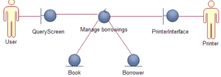
Some agile development methodologies have embraced the ro-bustness diagram as the first (or even the only) step in the building of the architecture of an application (see for example Agile Mod-eling [2] and Iconix [23]). Robustness diagrams use 3 UML stere-otypes called the Boundary, the Controller (or Control Object) and the Entity which have their own specific icon. They represent the three fundamental roles software elements could play in a system: communicating with the outside world (Boundary), stor-ing information (Entity) and processstor-ing information (Controller). The latter also coordinates the work of the other two elements (Boundary and Entity) to implement a use-case. Each use-case could be assigned either a single Controller to manage all the activities in the use-case or several Controllers to manage each individual subtasks in the use-case [1]. To represent the external entities (user or device) with which our own system must com-municate, UML uses the Actor modeling element. Although Ja-cobson initially recommended using one Boundary per actor [16], the trend today for human actors is rather to use one Boundary per screen or per interaction mode. In figure 1, we present the exam-ple of a robustness diagram for the Borrow Book use-case of a
3 Robustness diagram are supported in Rational Software Architect when
applying the UML profile : “RUP Analysis” to a model
simple library management system. User and Printer are actors.
QueryScreen and PrinterInterface are Boundary objects, Manage borrowings is a Controller and finally Book and Borrower are
both Entity objects. The links between the object represent collab-orations (as identified in the CRC cards [28] of each object).
Figure 1. Robustness diagram
These five objects represent the high level roles of the software elements required to implement the use-case. It is important to highlight that Boundaries are only interfaces to communicate with the actors. If the communication with an actor is complex, the handshake must be processed by a specific Controller [16]. In the example above, if the communication with the Printer is complex we could add a specific Controller to manage it. This diagram is well suited to the description of architectures at the communica-tion, data access and processing element level. This is indeed the right level of description to design distributed application archi-tectures, without delving into technical details that would hide the key elements’ responsibilities.
Use case analysis is basically conducted in three phases. First: identify the candidate objects to implement the use-case:
Identify the actors and assign one Boundary object for each actor (one per screen or interaction mode for human actors). Identify the information sources accessed in the use-case
and create one Entity object per source.
Identify the subtasks in the use-case and assign a Controller to each of them. Also, assign a Controller to each complex communication with an actor.
Second: analyze each step of the use-case and assign responsibili-ties to each of the robustness objects involved in the step. The result of this analysis can be documented using CRC cards [28]. Third, verify that the collaboration of all the analyzed robustness objects do implement the behavior specified by the use-case. Sequence diagram are sometimes used to perform this validation. The integrity rules for robustness diagrams are simple [22]:
Actors can only communicate with Boundaries. Boundaries can only communicate with Controllers. Entities can communicate with Controllers and Entities. Controllers can communicate with all objects.
This technique works well to represent the responsibilities of the components of a distributed application [18]. When an application is split in two or more subsystems distributed over a network, each subsystem sees the other subsystems it must collaborate with as actors (Figure 2).
Boundaries are therefore used to communicate with these actors. Following the same idea, from a mobile device the server system it must collaborate with is considered as an actor. The same is true for the mobile device seen from the server.
4. Component’s functional semantics
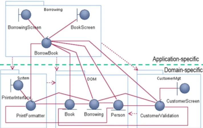
When designing the large grain logical architecture of an applica-tion, which is done early in a project, one key step is to identify the components and assign them responsibilities. This is challeng-ing since the components’ responsibilities come from the con-tained implementation classes which are unknown at this stage. However, the robustness diagram can help. Indeed, by assigning robustness objects to a component we simultaneously define its functional semantics. The latter will be derived from the contained robustness objects’ responsibilities. The size of the components (the number and kind of robustness objects contained) is decided based on the coupling, cohesion and reuse potential of the compo-nent. Cohesion and coupling can be determined from the collabo-ration among the robustness objects that is described in their CRC cards [28]. In figure 3 we present the way the semantics is as-signed to a component which comes from the responsibilities of the contained robustness objects. As we can observe, the
Custom-erMgt component contains two robustness objects. Its
responsibil-ities are therefore those described in the contained objects’ CRC card. In the CustomerValidation CRC card we see that the Con-troller must collaborate with the Entities Person, Book and
Bor-rowing located in another component. Therefore this creates some
coupling between both components.
Figure 3. Component semantics
As the next step in the design of a logical architecture, the com-ponents can be arranged in layers to reflect their reuse potential. Figure 4 presents the logical architecture of our simple library application. We only present the borrow book service which uses the customer validation service. In the application-specific layer we place the Borrowing component which represents an end-user service specified by a use-case. This component uses the
Custom-erValidation component whose responsibility is to validate the
information about the customer (display of the customer’s infor-mation, validate the number of books borrowable simultaneous-ly,…). Since the latter is potentially reusable by some other appli-cation-specific component, it is located in the domain-specific layer. The DOM component (Domain Object Model) contains the access to the information data sources, in particular the infor-mation on users, books and borrowings. Finally the System com-ponent is responsible for the printing services. It contains the printer interface (Boundary) and a Controller used to manage the
communication with the printer which is supposed to be complex. In particular, this Conroller would format information before sending it to the printer.
Figure 4. Logical architecture of a simple library system
5. Distributed vs mobile computing
Traditionally, applications get distributed to satisfy several quality attributes such as performance, reliability, security, etc [26]. The implementation is usually distributed among several powerful server machines in well monitored environments. But in the case of the mobile version of an enterprise application the situation is quite different. The motivation is to make information more ac-cessible by adding a new information distribution channel. But the mobile devices are neither as powerful nor as seamlessly connect-ed as the server machines. In particular, when information is stored both on the mobile and on the server, intermittent network access may lead to a partition [6]. Therefore, the quality attributes to address with the mobile version of the enterprise application are
1. Usability 2. Performance 3. Maintainability
4. Consistency of application’s data 5. Availability of service
6. Partition tolerance
Although usability and performance have probably been properly addressed when building the desktop version of the enterprise application, they must be reworked to adapt it to the mobile de-vice’s environment (screen size, specific input devices, low com-munication bandwidth,…). Maintainability must also be ad-dressed because it is highly desirable not to worsen the maintaina-bility of the application when moving it to the mobile. The last three quality attributes are closely interdependent through the famous CAP theorem [6]. When the mobile device is disconnect-ed from the network, users of the enterprise app should nonethe-less be able to continue working with the device. In this case, the challenge is to manage the partition explicitly by properly detect-ing it and recoverdetect-ing it [6]. For example this challenge has been faced by the designers of Agropedia [20], a big agricultural knowledge base and social media in India, when moving to the mobile. Indeed, when working in a rural location in India, the network may not be available at all but the users must nonetheless be able to work with the application4. In order to cope with the
problem, the first step to architect the mobile version of the appli-cation is to assess the desired value for each quality attribute. Next the application must be architected to comply with these quality attribute values [4]. It is worth mentioning that the Mobile Cloud Computing approach is not an answer to the network availability problem since it requires all computation and data storage be localized in the cloud [11]. This supposes accessibility to the Mobile Network services. As far as application architecture is concerned, to enhance maintainability all these constraints and challenges must explicitly be dealt with in the design. This is an instance of the Designers’ Paradox [14]: “If you want to be flexi-ble and independent of something, it must be explicitly covered in the design; otherwise you risk an implicit coupling that resists change”. These design constraints will therefore be explicitly represented in the robustness model and the responsibilities ob-jects.
6. Robustness diagram for mobile computing
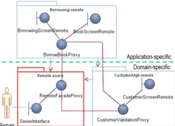
When moving an application to a distributed architecture, a few concepts from the Pattern community are helpful. First and fore-most the Proxy pattern followed by the Façade pattern [7][12]. However, to optimize the understandability of the mobile version of an enterprise app we apply the Mimic Architecture tactic i.e. we build, on the mobile, a component topology similar to that of the client-server version and add the communication components on both sides (on the mobile device and on the enterprise server). Next, we carefully adapt this logical architecture to account for the desired quality attributes while trying to maintain the under-standability of the resulting architecture. Let us consider again the example of the simple library system architecture (Fig.4). On the server side we must first add the component that will manage the remote access from the mobile device (Fig.5, highlighted).Figure 5. Logical architecture of the desktop version with remote access
At this level of granularity, the mobile device is modeled as an Actor connected to a specific Boundary (MobileInerface). Since the communication is complex, we must manage it explicitly. This is represented by the Controller object called RemoteFacade. Indeed this represents a Façade because all the services offered by the enterprise server will be access through this object. The com-munication component must be located in the application specific layer because it will expose services implemented by objects in the same layer and the layer below (BorrowBook and
Customer-Validation). Therefore it cannot be located in the domain specific
layer to comply with the strict top-down access principle among the layers. Now we must model the mobile device’s logical archi-tecture. We start with the same architecture as the desktop version but replace the Controllers with Controller proxies. At this level of design, proxies must be understood as responsibility proxies. Indeed they have the same responsibilities as their server’s coun-terpart but will actually forward some or all of the responsibility requests to them. The choice of the request to process locally or to forward to the server will depend on the desired quality attributes (availability, performance, consistency of data, partition toler-ance). Finally we must also add an extra component that will manage the remote access to the server (Fig.6, highlighted)
Figure 6. Mobile’s logical application architecture All the Boundaries but ServerInterface represent the UI on the mobile device and are therefore specific to the device. The
Bor-rowBookProxy and CustomerValidationProxy Controllers expose
the same services as their server counterpart. They process the requests issued from the screens either locally or by forwarding the request to their server’s counterpart. However, these proxies do not communicate with the remote server directly but through the communication component which contains the
RemoteFa-cadeProxy, the counterpart of the RemoteFacade on the server
The former is the single point of communication with the server. The RemoteAccess component on the mobile is not located in the application-specific layer but in the domain-specific layer since it must be accessible from the component in this very layer too (for example the CustomerValidation-remote component). This is the only topological dissymmetry between the logical architectures in the mobile and in the desktop versions. It must be highlighted that the mobile application architecture is “lighter” than the desktop version since most of the processing and data are located on the server and accessed through the proxies. But the topology remains globally the same which promotes better understanding by the maintenance engineer (provided that he knows the desktop ver-sion of course). The main specific parts in the mobile verver-sion of the application are the user interfaces represented by the bounda-ries in the Borrowing-remote and CustomerValidation-remote components. They must optimize the usability quality attribute (QA) through the relevant use of the UI tools of the device. The following figure (Fig.7) shows the communication path from a request issued through the BookScreenRemote on the mobile device to the book information source which contains the infor-mation to be displayed (the detailed inforinfor-mation on a book). Although this architecture is simple and optimizes the
under-standability QA hence the maintainability QA, it may not satisfy some of the other QA’s. In particular, performance may be heavi-ly impacted in case of poor network connection.
Figure 7. Communication path from the mobile to the server
7. Improving Performance Consistency &
Avalability
In the design presented above, a low network bandwidth will affect the Performance QA of the mobile application while an intermittent access to the network will impact its Availability QA.
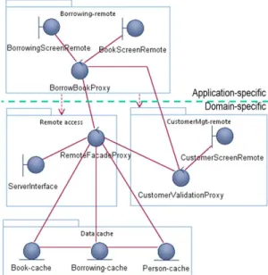
Figure 8. Mobile’s logical architecture with data cache To improve these QAs, one must add some extra responsibility to the proxies. To improve performance problems due to slow
net-work connections, we could implement a data cache managed by the RemoteFacadeProxy on the mobile device (Cache Proxy pattern [7]), see figure 8. If however the network connection may not be available all the time, we may decide to copy parts of the database on the device which will then lead to a partition. In this case the logical architecture on the mobile will even be closer to that of the desktop version (compare with figure 4). Hence, some of the services of the server application will be replicated to the corresponding proxies on the mobile, which will therefore become
semi-proxies. The choice of the services to replicate depends on
the required levels of the Performance, Consistency, Availability and Partition Tolerance QAs. Figure 9 presents such an option.
Figure 9. Mobile’s logical architecture with DB replication A new Controller (ReplicationMgr) has been introduced in the
DOM-remote component to manage the replication of data from
the server to the mobile device. Finally, on the server side the multiple accesses from several mobile devices could be controlled by the RemoteFacade to implement different synchronization strategies using for example the Proactor pattern [26]. This be-havior will consequently be documented in the CRC card of the
RemoteFacade object.
8. Conclusion
In this paper we present an approach to model the high level logical architecture of mobile enterprise applications. We applied it to the problem of the migration of a desktop-based client server enterprise application to the mobile. The technique is based on a well-known modeling technique: the UML Robustness Diagram, supplemented by architectural patterns. We have showed how this diagram can help the designers to address and document the key architectural decision in the process, without delving into tech-nical details. We found this technique to be at the adequate granu-larity level to let the designer select the fundamental architectural options while staying agile. In particular, the distribution of pro-cessing and data can easily be represented. In contrast with the approaches based on MDE, our proposal represents a higher level of abstraction and does not target the same issue. Rather than trying to generate code from a model, then requiring this model to include all the specifications to the finest level of logical details, we stay at a higher level of abstraction to represent only the large grain options. To increase the software architecture understanda-bility, we propose a new tactic for the migration of enterprise applications to the mobile: Mimic Architecture. This tactic sug-gests that the software on the mobile be architected similarly to
that of the desktop version. Therefore, the maintenance engineers will be able to immediately understand the role and responsibili-ties of the components on the mobile since they are supposed to know already the architecture of the desktop version. Our contri-bution is therefore:
1. To show how the robustness objects can be used to specify the functional semantics of the components of some logical software architecture.
2. To show how the robustness diagram can help with the ar-chitecting of the mobile part of an enterprise application. 3. The proposal of a new tactic, Mimic Architecture, to
im-prove the understandability hence the maintainability of mobile enterprise apps.
9. State of the art
Although research papers abound in the domain of code writing and generation for the mobile platform, there are almost no refer-ences on the migration of enterprise app to the mobile and on the high level modeling of such applications. For example Parada and de Brisolara [21] present and MDE approach for android which target the very detailed level of application architecture. The same is true to the approach of Balagtas-Fernandez [5], Khambati et al. [19], Heitkötter et al. [13] or Roychoudhury and Kulkarni [24]. The proposal of Bowen and Hinze [8] also target the generation of code from models but the latters are much more formal than in our approach. Indeed the generated code can be inputted to a device emulator of their own. Again, in all these approaches, the models required to generate the code are very detailed and obfuscate the key decision to satisfy the QAs. Moreover this level of model design is not very compatible with the agile processes.
Acknowledgement
The author would like to express his gratitude to Prof. T.V. Prab-hakar from IIT Kanpur, India, for very helpful discussion on the mobile version of the Agropedia system [20].
References
[1] Ambler S. Robustness Diagrams. http://www.agilemodeling.com/ artifacts/robustnessDiagram.htm. (Accessed in August 2013). [2] Ambler S. Agile Modeling: Effective Practices for eXtreme
Pro-gramming and the Unified Process. Wiley (2002).
[3] Appcelerator/IDC Q2 2013 Mobile Developer report.
www.appcelerator.com.s3.amazonaws.com/pdf/developer-survey-Q2-2013.pdf. (Accessed in August 2013).
[4] Bass L., Clements P., Kazman R. Software Architecture in Practice
3rd edition. Addison-Wesley (2013).
[5] Balagtas-Fernandez F.T. Model-Driven Development of Mobile Applications. Proc. 23rd IEEE/ACM Int. Conf. on Automated
Soft-ware Engineering (2008).
[6] Brewer E. CAP Twelve Years Later: How the “Rules” Have Changed. IEEE Computer 45(2) (Feb 2012).
[7] Buschmann F., Meunier R., Rohnert H., Sommerlad P., Stal M
Pattern-Oriented Software Architecture Volume 1: A System of Pat-terns. Wiley (1996).
[8] Bowen J., Hinze A. Supporting Mobile Application Development with Model-Driven Emulation. Proc. of the Fourth
International-Workshop on Formal Methods for Interactive Systems (2011).
[9] Cohn M. Succeeding with agile: software development using
Scrum. Addison-Wesley (2010).
[10] den Haan J. Why there is no future for Model Driven Development. www.theenterprisearchitect.eu/archive/2011/01/25/why-there-is-no-future-for-model-driven-development (Accessed in August 2013). [11] Dinh H.T., Lee C., Niyato D., Wang P. A survey of mobile cloud
computing: architecture, applications, and approaches. Wireless
Communications and Mobile Computing. wileyonlinelibrary.com, (Accessed in August 2013).
[12] Gamma E., Helm R., Johnson R., Vlisside J. Design Patterns:
Ele-ments of Reusable Object-Oriented Software. Addison-Wesley
(1995)
[13] Heitkötter H., Majchrzak T.A., Kuchen H. Cross-Platform Model-Driven Development of Mobile Applications with MD2. Proc of the
ACM Symposium on Applied Computing (SAC) (2013).
[14] Hubert R. - Convergent Architecture: Building Model-Driven J2EE
Systems with UML. Wiley (2002).
[15] IDC Predictions 2013: Competing on the 3rd Platform. www.idc.com/research/Predictions13/downloadable/238044.pdf (Accessed in August 2013).
[16] InfoQ Survey: The State of Mobile Development in Q3 2013. www.infoq.com/news/2013/07/state-mobile-2013. (Accessed in August 2013).
[17] Jacobson I. Object Oriented Software Engineering: A Use Case
Driven Approach. Addison-Wesley (1992).
[18] Jacobson I., Griss M., Jonsson P. Software Reuse. Addison-Wesley (1997).
[19] Khambati A., Grundy J., Warren J., Hosking J. Model-driven De-velopment of Mobile Personal Health Care Applications. Proc.
IEEE Int. Conf. of Automated Software Engineering (ASE) (2008).
[20] Pappu N., Sarkar R., T.V. Prabhakar. Agropedia: Humanization of Agricultural Knowledge. IEEE Internet Computing 14(5). (Sept.-Oct. 2010).
[21] Parada A.G., de Brisolara L.B. A model driven approach for An-droid applications development. Proc. Brazilian Symposium on
Computing System Engineering (SBESC) (2012).
[22] Rosenberg D. Use Case Driven Object Modeling with UML : A
Practical Approach. Adison-Wesley (1999).
[23] Rosenberg, D., Stephens, M. & Collins-Cope, M. Agile
Develop-ment with ICONIX Process. Apress (2005).
[24] Roychoudhury S., Kulkarni V. Mobile Enabling Enterprise Busi-ness Applications Using Model driven Engineering Techniques.
Proc. 2nd Workshop on Software Engineering for Mobile Applica-tion Development MobiCase'11 (2011).
[25] Rugaber S. - Program Comprehension For Reverse Engineering.
Proc. AAAI Workshop on AI and Automated Program Understand-ing. (1992).
[26] Schmidt D., Stal M., Rohnert H., Buschmann F. Pattern-Oriented
Software Architecture Volume 2: Patterns for Concurrent and Net-worked Objects. Wiley (2000).
[27] Wasserman A.I. - Software Engineering Issues for Mobile Applica-tion Development. Proc. 2nd Workshop on Software Engineering
for Mobile Application Development MobiCase'11 (2011).
[28] Wirfs-Brock R., McKean A. Object Design: Roles, Responsibilities,
and Collaborations. Addison-Wesley (2003)
[29] Zend Developer Pulse Survey - Second Quarter 2013. http://static.zend.com/topics/Zend-Developer-Pulse-report-Q2-2013-0523-EN.pdf (Accessed in August 2013).