HAL Id: hal-00329765
https://hal.archives-ouvertes.fr/hal-00329765
Submitted on 5 Jun 2013
HAL is a multi-disciplinary open access
archive for the deposit and dissemination of
sci-entific research documents, whether they are
pub-lished or not. The documents may come from
teaching and research institutions in France or
abroad, or from public or private research centers.
L’archive ouverte pluridisciplinaire HAL, est
destinée au dépôt et à la diffusion de documents
scientifiques de niveau recherche, publiés ou non,
émanant des établissements d’enseignement et de
recherche français ou étrangers, des laboratoires
publics ou privés.
Benjamin Fournier, Maxime Sauzay, Christel Caës, Michel Noblecourt, Michel
Mottot, Annick Bougault, Véronique Rabeau, André Pineau
To cite this version:
Benjamin Fournier, Maxime Sauzay, Christel Caës, Michel Noblecourt, Michel Mottot, et al.. Lifetime
prediction of 9-12%Cr subjected to creep-fatigue at high temperature. ECF 17, Sep 2008, Brno, Czech
Republic. pp.1366-1372. �hal-00329765�
Lifetime prediction of 9-12%Cr subjected to creep-fatigue at
high temperature
B. Fournier
1,*, M. Sauzay
1, C. Caës
1, M. Noblecourt
1, M. Mottot
1, A
Bougault
1, V. Rabeau
1, A. Pineau
21
CEA Saclay, DEN/DANS/DMN/SRMA, bât 455, 91191 Gif sur Yvette Cedex, France
2
ENSMP, Centre des Matériaux P.-M. Fourt, UMR CNRS 7633, BP 87, 91003 Evry, France * corresponding author : benjamin.fournier@cea.fr
Keywords: Creep-fatigue, high temperature, martensitic steel, modelling, oxidation.
Abstract. Based on the experimental identification of the relevant damage mechanisms, a model is
proposed to predict the creep-fatigue lifetime of 9-12%Cr steels. Crack propagation tests are necessary to identify the parameters of the model. Even though the damage mechanisms were identified at 550°C, the model turns out to remain applicable between 20°C and 600°C in pure fatigue and between 500°C and 600°C in creep-fatigue.
Introduction
The 9-12%Cr martensitic steels are under study for several components of the generation IV nuclear reactors and fusion reactors. In these future applications, in addition to long holding periods (typically one month), cyclic loadings corresponding to start and stop-operations and maintenance must also be taken into account. Creep-fatigue lifetime must therefore be considered to design the corresponding components. As creep-fatigue tests with such long holding periods cannot be carried out in laboratory, the data must be extrapolated from short term tests.
The damage mechanisms of a modified 9Cr–1Mo martensitic steel (the exact chemical composition of the material under study is given in [1]) subjected to creep–fatigue loadings at high temperature were identified through detailed observations by optical and electronic microscopy mainly and reported previously [1,2]. The main conclusions of these observations were:
_ For all tested strain amplitudes, and for all test conditions (pure fatigue (PF), creep-fatigue (CF) and fatigue with stress relaxation (RF)) and durations of the holding period, damage is mainly transgranular. No intergranular cavitation could be observed, at least for holding periods shorter than 1h.
_ Oxidation is a key phenomenon to explain the cyclic lifetime.
_ All the tested samples can be separated into two categories, depending on the strain amplitude and on the duration of the holding period. These two categories correspond to two distinct types of damage mechanisms leading to fracture. Their main characteristics are reported below.
In type 1 damage, crack initiation proceeds by the usual mechanisms (fatigue extrusions/intrusions, surface defects, ...) although it is probably accelerated by the existence of an oxide layer. In this case only one main crack propagates and leads to final fracture.
In the domain where type 2 damage is observed, crack initiation occurs within the oxide layer, due to brittle fracture. The damaged oxide layer no longer prevents oxygen from penetrating inside the material. This oxygen penetration damages the microstructural boundaries (grain, block, lath and sub-grain boundaries), which facilitates the crack propagation. Moreover, the oxide scale cracking is repeated during the whole fatigue lifetime, therefore a large number of cracks initiate and then propagate, leading to crack coalescence.
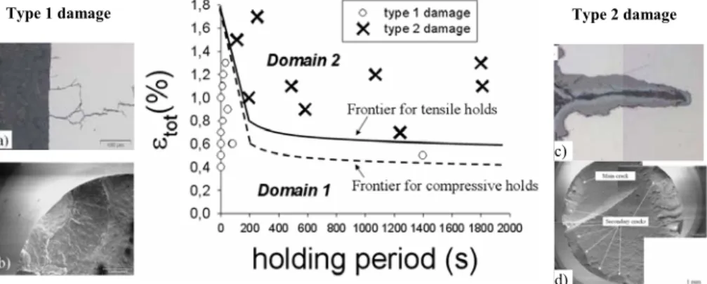
The most deleterious type of damage is named type 2. The range of loading conditions corresponding to each type to damage has been experimentally identified through detailed observations of numerous fractured specimens. These ranges depend on the holding direction (tension or compression), see Fig. 1. Two illustrative frontiers between type 1 and type 2 damage were plotted, stressing the fact that tests carried out with a compressive holding period lead more easily (for a lower applied strain) to type 2 damage than their tensile counterpart. This was explained in more details in [1,2].
Figure 1 - Type of damage (1 or 2) for CF tests carried out with a tensile holding period and located in a [εεεεtot
(=ΔεΔεΔεΔεfat+εεεεcreep), hold time] plane. The full line illustrates the frontier between the two domains of loadings for
tensile holding periods, whereas the dashed line presents the same frontier, but observed on specimens subjected to CF tests with a compressive hold. Crack morphologies and density are illustrated for the two types of damage
by the SEM observations of a longitudinal cross section (a and c) and the fracture surface (b and d).
A physically based-model of the previously identified damage mechanisms is first proposed. The crack propagation tests carried out to identify the parameters of the model are then described and the lifetime predictions are compared to the experimental values. The extrapolations of this model to other testing conditions are finally discussed.
Modelling
The creep-fatigue lifetime (Nf) is divided into an initiation (Ni) and a propagation (Np) part:
p i
f N N
N = + (1)
For type 1 damage, Ni is calculated through the Tanaka and Mura [3] model, since
extrusions/intrusions were observed both at room temperature [4-6] and at 550°C in vacuum [7]:
2 p i d N ε α Δ = (2)
Type 1 damage Type 2 damage
c)
Where Į is a temperature dependent constant, d is the grain size and ǻİpis the plastic strain range
applied per cycle.
For type 2 damage, crack initiation is considered to occur at the first cycle because of the brittle fracture of the oxide layer. Therefore the lifetime is only controlled by the crack propagation rate. For both types of damage, the crack propagation is modeled thanks to the Tomkins [8] formulation:
( )
¸¸¹ · ¨ ¨ © § ¸ ¹ · ¨ © § Δ + × × Δ Δ = 2 2 2 2 2 2 8 1 2 8 T a T dN da π εp σ π σ (3)With a the crack length, ǻı the stress range applied at Nf/2 and T standing for the residual tensile
strength of the material after a fatigue loading.
And =
³
ac a P dN da da N 0 (4)Where a0 is the crack length at crack initiation (arbitrarily set to 50µm ~ former austenitic grain
size) and ac is taken equal to the sample radius.
Coalescence is also roughly modeled by considering the propagation of 5 cracks for type 2 damage.
Material parameters identification
Even though numerous studies were dedicated to crack propagation rate measurements, most of them were made under elastic conditions [9-21]. Therefore dedicated crack propagation tests were carried out at 550°C in the low-cycle fatigue range of loading. An optical tracking device was used to measure the crack length during the test. The detailed experimental procedure is given in [22]. Fig. 2.a presents an example of the observations made during crack propagation tests. Figure 2.b presents the crack length measured during pure-fatigue and relaxation-fatigue (these tests were not necessary for the parameters identification, but they enabled us to check that a stress-relaxation holding period has only very little effect on the crack propagation rate) crack propagation tests. As suggested by the literature, the crack growth rate is roughly proportional to the crack length. This validates the choice of the Tomkins law to model crack propagation.
To identify the value of the parameter Į used in the crack initiation law, the experimental value of the pure fatigue lifetime, obtained at a strain range Δεfat = 0.4%, was used.
Results and discussion
Figure 2 - a) Observation made during a crack propagation test and b) crack length plotted as a function of the number of cycles. th stands for the holding period in stress relaxation.
Figure 3 - Comparison between experimental and predicted PF lifetimes. The Manson Coffin law fitted on the experimental lifetimes is shown in dashed line. The number of cycles to crack initiation Ni is also reported. The
values of the plastic deformation are measured at Nf/2. ΔεΔεΔεΔεp is the plastic strain range applied. N50 corresponds to
the number of cycles necessary to reach a 50% decrease of the stress, which is usually considered as the number of cycles to fracture.
Except for Δεvp§ 0.1 %(which corresponds to Δεfat = 0.4%) that was used during the parameters
identification procedure, all the other points are true validation points: the only informations given to the model are those necessary for equations 2 and 3. It shows that the model gives excellent agreement for Δεfat 0.4%. For lower strain range, the fully plastic assumption is not valid anymore.
Fig. 4 compares the predictions of the model with the experimental lifetimes for creep-fatigue tests. In Fig. 4.a, one can see that all predictions fall into the range [Nexp/2, 2Nexp] which is usually
considered as a reasonable error band in creep-fatigue. In addition, as shown in Fig. 4.b even complex phenomena are reproduced, such as the shorter lifetimes associated to compressive holding periods compared to tensile holding periods.
A detailed review of fatigue and creep-fatigue lifetime data on 9-12%Cr steels [23] showed that the damage mechanisms identified on this modified 9%Cr steel were relevant for all the other steels of this family. In addition, it was shown that whatever the temperature (between 20°C and 600°C), the pure fatigue lifetime was found to follow the same Manson-Coffin curve, meaning that the level of plastic strain applied is prevalent compared to oxidation effects in pure fatigue. Therefore the present model should also apply for other temperatures in pure fatigue. This is verified in Fig. 5
where the predicted fatigue lifetimes are compared to experimental values at 20°C and 400°C. Here
the T and the Į values had to be identified again, as explained in [22]. Except for the lowest strain
range (used for identification) the two other strain ranges are also validation points, showing that the proposed model is relevant for a large range of temperature.
For creep-fatigue lifetime, the model can be used as long as the oxidation effects remain comparable to those observed at 550°C, therefore one must be more careful in extrapolating test results, and the validity of the model can be safely extended between 500°C and 600°C. For other temperatures the damage mechanisms must be checked by direct observations.
Figure 4 – a) Comparison of experimental and predicted CF lifetimes, considering the propagation of 5 cracks for type 2 damage. The values of ǻİp and ǻı are measured at N50/2. The empty symbols correspond to type 2
damage whereas the filled symbols correspond to type 1 damage. Various creep strains were applied for each ǻİfat value. b) Creep-fatigue lifetime difference between tensile and compressive holding periods.
Figure 5 - Comparison of the predicted fatigue lifetimes with the experimental values at a) 20°C and b) 400°C. Δε
ΔεΔε
Δεp is the plastic strain range. Conclusions
Based on the damage mechanisms identified on creep-fatigue tests carried out at 550°C, a physically-based model is proposed to predict the creep-fatigue lifetime of 9-12%Cr steels. The following conclusions can be drawn from the present study:
• The proposed model is identified on a limited number of tests (four crack propagation tests and the mean lifetime in pure fatigue for only one strain range).
• It predicts accurately the pure fatigue lifetimes for Δεfat 0.4%
• If the crack density is taken into account, the model is able to predict the lifetime in the usual scatterband [Nexp/2, 2Nexp] for all the strain amplitudes and for all the holding
period durations tested experimentally in creep–fatigue and relaxation-fatigue.
• In pure fatigue the available results, in addition to literature data, suggest that the proposed model is valid for all temperatures between 20 °C and 600 °C.
References
[1] Fournier, B., Sauzay, M., Caës, C., Noblecourt, M., Mottot, M., Bougault, A., Rabeau, V., Pineau, A., Creep-Fatigue-Oxidation interactions in a 9Cr-1Mo martensitic steel, Part I: Effect of tensile holding period on fatigue lifetime, Int. J. Fat., 30, 649-662, (2008).
[2] Fournier, B., Sauzay, M., C. Caës, M. Noblecourt, M. Mottot, A. Bougault, V. Rabeau, A. Pineau, Creep-Fatigue-Oxidation interactions in a 9Cr-1Mo martensitic steel, Part II: Effect of compressive holding period on fatigue lifetime Int. J. Fat., 30, 663-676 (2008).
[3] Tanaka K, Mura T., J Appl Mech , 48, 97–103, (1981).
[4] Fournier B, Sauzay M, Caës C, Mottot M. Analysis of the hysteresis loops of a martensitic steel. Part I: study of the influence of strain amplitude and temperature under pure fatigue loadings using an enhanced stress partitioning method.Mater Sci Eng A, 437 (2006)
[5] Verleene A, Vogt J-B, Serre I, Legris A. Low cycle fatigue behaviour of T91 martensitic steel at 300 °C in air and in liquid lead bismuth eutectic. Int J Fatigue 28 (2006).
[6] Earthman JC, EggelerG, Ilschner B.Deformation and damage processes in a 12%Cr–Mo–V steel under high temperature low cycle fatigue conditions in air and vacuum.Mater Sci Eng A 110 (1989)
[7] Fournier B, Sauzay M, Caës C, Noblecourt M, Mottot M, Bougault A, et al. Durée de vie en fatigue-fluage à haute température des aciers martensitiques a 9%Cr: interactions fatigue/fluage/oxydation. In: Actes de congrès du colloque MECAMAT2007. Aussois, France (2007).
[8] Tomkins B., Philos Mag, 18, 1041–66 (1968).
[9] Ogata T, Yamamoto M. High-temperature fatigue crack propagation property of Mod.9Cr– 1Mo steel under vacuum and air conditions. JSME Int J, 40 (1997).
[10] Skelton RP. Cyclic crack growth properties of service-exposed ferritic steels for use in thermal fatigue assessments. Mater High Temp, 22 (2005).
[11] Nakamura H, Murali K, Minakawa K, McEvily AJ. Fatigue crack growth in ferritic steels as influenced by elevated temperature and environment. Microstruct Mech Behav Mater, 1, (1985).
[12] King JE, Cotterill PJ. Role of oxides in fatigue crack propagation. Mater Sci Technol, 6 (1990)
[13] Okamura H, Ohtani R, Saito K, Kimura K, Ishii R, Fujiyama K, et al. Basic investigation for life assessment technology of modified 9Cr–1Mo steel. Nucl Eng Des, 193 (1999).
[14] Ebi G, McEvily AJ. Effect of processing on the high temperature low cycle fatigue properties of modified 9Cr–1Mo ferritic steel. Fatigue Eng Mater Struct, 7 (1984).
[15] Kim S, Kohyama A, Yoon H. Fatigue crack growth behavior and microstructure of reduced activation ferritic/martensitic steel (JLF-1). Fusion Eng Des 81 (2006).
[16] Yoon H, Lee S, Min B, Kim S, Katoh Y, Kohyama A. Fatigue life and fatigue crack propagation behavior of JLF-1 steel. Fusion Eng Des, 61–62 (2002).
[17] Aktaa J, Lerch M. Near-threshold fatigue crack behaviour in EUROFER 97 at different temperatures. J Nucl Mater 333 (2006).
[18] Chaswal V, Sasikala G, Ray S, Mannan S, Raj B. Fatigue crack growth mechanism in aged 9Cr–1Mo steel: threshold and Paris regime. Mater Sci Eng A, 395 (2005).
[19] Filippini E. The martensitic steels 9Cr–1Mo modified types as possible candidate alloys for high temperature plants. ENEA, Contract RA1 CT/94/0239-IT; 1996.
[20] Haärkegard G, Denk J, Stärk K. Growth of naturally initiated fatigue cracks in ferritic gas turbine rotor steels. Int J Fatigue, 27 (2005).
[21] Maile K, Klenk A, Granacher J, Schellenberg G, Tramer M. Creep and creep–fatigue crack behavior of 1Cr- and 9Cr-steels. Key Eng Mater, 171–174 (2000)
[22] Fournier, B., Sauzay, M., Caes, C., Noblecourt, M. Mottot, M., Bougault, A., Rabeau, V., Man, J., Gillia, O., Lemoine, P., Pineau, A., Creep-Fatigue-Oxidation interactions in a 9Cr-1Mo martensitic steel, Part III: lifetime prediction, Int. J. Fat., in Press.
[23] Fournier, B., Creep-fatigue of 9-12%Cr steels: behaviour and damage, PhD Thesis, Ecole des Mines de Paris, France, 2007.