HAL Id: hal-02337249
https://hal.archives-ouvertes.fr/hal-02337249
Submitted on 29 Oct 2019
HAL is a multi-disciplinary open access
archive for the deposit and dissemination of
sci-entific research documents, whether they are
pub-lished or not. The documents may come from
teaching and research institutions in France or
abroad, or from public or private research centers.
L’archive ouverte pluridisciplinaire HAL, est
destinée au dépôt et à la diffusion de documents
scientifiques de niveau recherche, publiés ou non,
émanant des établissements d’enseignement et de
recherche français ou étrangers, des laboratoires
publics ou privés.
Advanced mechanical modeling of cyclically loaded
cable-in-conduit conductors for fusion magnets
Rebecca Riccioli, Alexandre Torre, Damien Durville, Marco Breschi, Frédéric
Lebon, V. Tronza
To cite this version:
Rebecca Riccioli, Alexandre Torre, Damien Durville, Marco Breschi, Frédéric Lebon, et al.. Advanced
mechanical modeling of cyclically loaded cable-in-conduit conductors for fusion magnets. 26th edition
of the International Conference on Magnet Technology, Sep 2019, Vancouver, Canada. �hal-02337249�
Advanced modeling of
electromagnetic loading of cable-in-conduit
conductors for fusion magnets
R. Riccioli, A. Torre, D. Durville, M. Breschi, F. Lebon, and V. Tronza
Abstract— The electrical performance degradation of Nb3Sn ca-bles in the Cable-in-Conduit Conductors CICC has been well doc-umented in literature. The Nb3Sn composite strands exhibit a criti-cal current density that strongly depends on the strain state of the superconducting filaments. During a fusion magnet operation, the conductors are submitted to several electromagnetic and thermal cycles affecting the Nb3Sn mechanical state and consequently the capacity of the conductors to transport current. Different studies based on both a macroscopic and microscopic approaches have been performed so far to identify the mechanisms determining the conductors’ behavior. Nevertheless, no theory permitting to predict the electrical performance of cyclically loaded conductors has been developed yet. Therefore, a solid electromechanical model able to tackle the analysis of CICC for fusion cables when they undergo thousands of cyclic loadings would be very useful.
In this paper an advanced mechanical model to study the me-chanical behavior of ITER TF CICC based on an improved ver-sion of the MULTIFIL finite element code is presented. A correc-tion is introduced to solve the problem of the non-homogenous strain distribution during the simulation of the thermal loading, encountered in a previous work. The model was adapted to take in-to account the Lorentz force cumulative effect of the other petals on the one under analysis.
An assessment of the electromagnetic behavior based on the me-chanical analysis is also presented.
Index Terms— CICC, Nb3Sn, Fusion, Superconducting Mag-net.
I. INTRODUCTION
okamak reactors enable fusion reactions thanks to ther-monuclear control. Very hot temperatures must be achieved and plasma has to be confined through intense mag-netic fields. Very high current conductors (~68 kA) are need-ed, imposing magnets made with superconductors to avoid
Manuscript received September 24, 2019.
R. Riccioli is with the CEA, Commissariat à l'énergie atomique et aux énergies alternatives, Cadarache, France and also with Aix-Marseille University and with Bologna University, Italy (e-mail: rebecca.riccioli@cea.fr).
A. Torre is with the CEA, Commissariat à l'énergie atomique et aux énergies alternatives, Cadarache, France (e-mail: alexandre.torre@cea.fr).
D. Durville is with MSSMat Laboratory (Mechanics of Soils, Structures and Materials), Centrale Supélec, CNRS UMR8579, Université Paris Saclay, France (e-mail: damien.durville@centralesupelec.fr).
M. Breschi is with the Department of Electrical, Electronic and Information Engineering, University of Bologna, Italy, Viale del Risorgimento 2, 40136 Bo-logna, Italy (e-mail: marco.breschi@unibo.it).
F. Lebon is with Aix-Marseille Université, CNRS, Centrale Marseille, LMA (Laboratoire de Mécanique et Acoustique), France (e-mail: flebon@lma.cnrs-mrs.fr).
V. Tronza is with IO (ITER Organization), France (e-mail: vladi-mir.tronza@iter.org).
huge electrical power dissipation. The critical current density of Nb3Sn based superconducting wires is not only function of
temperature and magnetic field, but also of the superconductor strain state [1]. Even though the critical current density varia-tion with magnetic field and temperature is well known for a superconducting wire [2], it is much more complex for a cable made of thousands of wires. In particular, the cable perfor-mance is tightly linked to the individual strands strain state, and to its evolution with operating loads [3].
Today, there is no method or tool, except full scale test campaigns, to foresee the impact of the mechanical state on the critical current density of the cable due to the mechanical loadings, and to anticipate the conductor electrical perfor-mances during its life in the tokamak.
II. MULTIFIL CODE
A. Introduction
This paper is a continuation of a previous work [4] having as a main goal to create an electromechanical model to simulate the behavior of a Cable-In-Conduit Conductor (CICC) in op-eration. The model is based on an upgraded version of the MULTIFIL code [5], which corrects the bias arising during the cool-down simulation that was creating artificially high compressive state at the cable ends [4].
B. Improvements in the taking into account of frictional con-tact interactions with rigid tools during cool-down
The simulation on the cool-down stage is aimed to repro-duce the global axial compression resulting from the differen-tial of thermal expansion between the jacket and the cable. To do this, an incremental axial displacement is applied to one end of the cable, while it is maintained inside a set of four rig-id tools described by analytical surfaces and forming a petal-shaped cylinder, by considering frictional contact interactions between the strands of the cable and these analytical surfaces. The issue faced with the previous version [4] was that, since the surfaces describing the tools around the cable are consid-ered as rigid, the relative displacement between the strands and the rigid tools induced by the displacement prescribed to one end of the cable, was larger on the side of this end, and was decreasing moving towards the other end. Due to the fric-tional tangential reactions exerted by the tools, the resulting axial compression was not constant along the considered sam-ple, but was decreasing from one end to the other. To
2
come this difficulty, during the axial compression stage, a cor-rection is made to the calculation of the relative displacements between the strands and the rigid tools, by assuming that the contacting points on the rigid tools move as if the tools were deforming uniformly. By this way, friction between the strands and the rigid tools is fully considered in all directions during the simulation of the cool-down, which is important to prevent possible local buckling, while accounting for an axial deformation of the tools.
III. MODEL HYPOTHESES &BOUNDARY CONDITIONS
A. ITER TF Cable-In-Conduit Conductor
Simulations performed in this paper are based on a geome-try following the design of the CICC for the TF coils of the ITER project. Such cables are characterized by 1422 strands twisted multi-stage cable, different twist pitches for each stage, and enclosed into a stainless steel jacket that is com-pacted onto the cable until around with a 30 % void fraction. The cable can be divided into six main sectors of 237 strands, called ‘petals’, which represent the last but one cabling stage. Each petal is composed of 150 superconducting Nb3Sn
com-posite strands and 87 copper strands. The six petals are twisted around a central steel spiral. Strands have a diameter of 0.82 mm, the inner jacket radius is 19.62 mm and the outer spiral radius is 5.05 mm.
B. MULTIFIL simulations and hypotheses
Thanks to MULTIFIL, it is possible to study the mechanical strain state over the strands for the main phases of the conduc-tor life. This includes cable manufacture, compaction inside the jacket, heat treatment at 650 °C to create the superconduct-ing Nb3Sn phase, thermal loadings due to cool-down to 4.5 K
and the application of electromagnetic loadings. Here, the EM loading is relevant to the SULTAN test conditions (nominal current 68 kA, background field 11.78 T) [6]. More details about how theses phases are simulated are given in the previ-ous work [4].
The model created in MULTIFIL takes into account just one petal of the cable to reduce the numerical computation time. The simulated petal is untwisted and has a reduced length of 300 mm comparable to the petal twist pitch in the conductor. The material constitutive laws for Cu and Nb3Sn
strands (elastic for manufacturing and elastoplastic for the other phases) are at room temperature. The heat treatment is simulated by resetting the stress and strain maps triggered by the cabling and compaction stage. The cool-down (600 °C – 4.5 K) is simulated by applying to the petal a global axial compression of -0.67 % through the boundary conditions. Up to now, the Lorentz force was simulated by applying uniform longitudinal loads over the strands length acting orthogonally to the strands axis (strands trajectories are taken into account).
C. Multi-petal Boundary conditions
One of the hypotheses of the numerical model is the simula-tion of one petal instead of the whole cable. When the elec-tromagnetic loading is applied, it is important to consider the cumulative effect of the other petals on the simulated one. To
simulate this loading, we developed ‘multi-petal’ analytical models. Two models have been developed: the rigid model (RM) and the fluid model (FM).
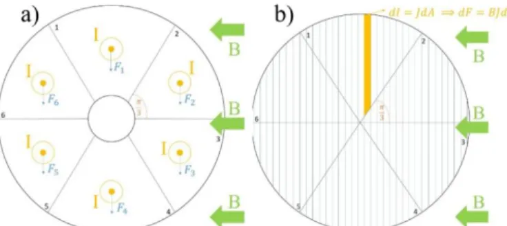
The RM is characterized by six petals interacting with each other like rigid bodies. The Lorentz force of each petal is con-centrated at the petal center and the cumulated Lorentz force is transmitted to the other petals through the petals’ interfaces. In the FM the Lorentz force is accumulated vertically as in the case of a hydrostatic pressure. In both cases the petals are un-twisted, the geometry is ideal, the injected current has a ho-mogeneous distribution and the model does not take into ac-count petals-jacket and petal-petal friction. The magnetic field is assumed as uniformly distributed for both cases. Figure 1 il-lustrates the two models.
Thanks to these models, it is possible to find the boundary conditions to be applied to the studied petal during the simula-tion of the electromagnetic cycle in MULTIFIL code.
Fig. 1. a) Whole cable rigid analytical model for the EM loading and b) whole cable fluid analytical model for EM loading.
These two models do not give exactly the same results, since the force distribution is quite different in each case. To choose which one is more relevant to a given cable, it is useful to recall that the RM is representative of a cable in which the petal can act as a rigid body. Therefore, it would be more rep-resentative of a tightly compacted cable with strong mechani-cal bonding between strands. We believe it could be applied to model a short twist pitch (STP) highly compacted cable as the ITER CS cable [7]. The FM would then be more relevant of a loose cable with less compaction. It is here applied to the analysis of the TF long twist pitch cable (LTP).
D. Implementation of analytical models
Models with uniform magnetic field have been implement-ed in MULTIFIL for the study of the fourth petal for the simu-lation of 1 EM cycle when the transport current in the cable is 68 kA and the magnetic field is 11.78 T. Each petal is subject-ed to a total Lorentz force of 133.5 N/mm.
Since MULTIFIL loading cases are displacement-driven, the issue was to find the displacement to be applied to the lat-eral planes shaping the petal corresponding to the cumulated EM force on the fourth petal. To implement the RM, planes are moved orthogonally to the planes themselves. For the fluid model, planes are moved vertically. In Figure 2, the displace-ment of planes is shown for both models, along with the plot providing the displacement to be applied in each case to ac-count for the proper cumulated force.
Fig. 2. a) Implementation of the RM in MULTIFIL to simulate 1 EM cycle for the fourth petal and b) Implementation of the FM in MULTIFIL to simulate 1 EM cycle for the fourth petal.
The RM foresees the application of 400 N/mm on each pet-al plane, which is three times the Lorentz force of one petpet-al. The related displacement of planes is 0.249 mm. The FM im-poses to apply 103.5 N/mm on both planes, which is 0.77 times the petal Lorentz force, and corresponds to a vertical displacement of 0.32 mm. The above displacements are im-posed to reach the peak of the EM cycle, at which the transport current is maximum. To simulate the unloading phase of the cycle, the planes are moved back by following the same pattern for both cases.
IV. RESULTS
A. Thermal equilibrium study
Since the cable-jacket interaction does not bias the cool-down process (see Section II), the cable longitudinal rigidity during the cool-down phase can be computed. This allows try-ing and determintry-ing the cable-jacket equilibrium durtry-ing the cool-down. The code allows to gradually compress the petal to reach the right value of strain which should represent the equi-librium strain between the jacket and the cable after the tem-perature variation from 650 °C to 4.2 K. To find the equilibri-um strain at which to stop the compression of the petal in the MULTIFIL simulation, a study of the cable reaction force as a function of the applied longitudinal compression was per-formed and compared to the thermal properties of the stainless steel jacket under the same applied strains. The thermal prop-erties at 4.2 K of the stainless steel and of the Nb3Sn refer to
the work in [8]. For the cable the thermal properties are con-sidered to be the same for the pure Nb3Sn, so at 4.2 K the
ca-ble theoretically is deformed to a 0.72 % thermal strain. The jacket has a 1.51 % of strain at 4.2 K. The reaction force of the jacket was calculated by considering a section surface of 2.63 10-4 m² and a Young’s modulus of 208.5 GPa. Figure 3 shows the plot of the equilibrium between the mechanical characteristics of the jacket computed through the Young’s modulus and that of the cable obtained with MULTIFIL, giv-ing as result a thermal strain of 0.67 %.
Fig. 3 Study of the thermal equilibrium between the stainless steel jacket in red and the cable at 4.2 K in blue. The equilibrium is reach at -0.69 % of the applied strain to the cable.
B. Mechanical results analysis
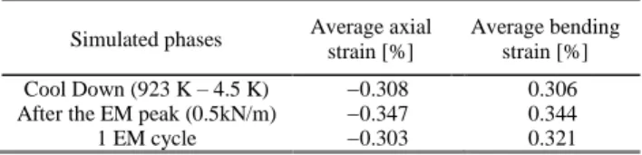
The study of the simulation of one thermal loading due to the 650° C - 4.2 K cool-down and of one EM cycle at (11.78 T, 68 kA) is here reported for the fluid model. In Table I, the average values of strain are reported for the simulated load-ings.
It is also possible to study the evolution of the strain distri-bution in the petal’s strands during the different compressive steps and the EM cycle. Figure 4 shows the gradual decreasing of the average strain during the cool-down and the parallel in-creasing of the distribution amplitude. The EM cycle release allows recovering the average strain value of the last compres-sive step.
Fig. 4 Evolution of the probability density function during the compressive proceeding and the EM cycle for the FM test case.
C. Statistical filaments breakage
It is useful to analyze the reduction of the Nb3Sn
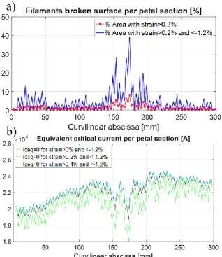
filamen-tary area in strands with respect to the total surface given by all the strands. This study gives access to the most solicited cable areas and to the consequent variations of the critical cur-rent density. In Figures 5a), the study of the fractured fila-ments surface per petal cross-section is reported after the peak
TABLEI
SUMMARY OF THE STRAIN VALUES AFTER THE FM SIMULATION
Simulated phases Average axial strain [%] Average bending strain [%] Cool Down (923 K – 4.5 K) 0.308 0.306 After the EM peak (0.5kN/m) 0.347 0.344 1 EM cycle 0.303 0.321
4
of the EM loading cycle. In Figures 5b), the equivalent critical current per petal section is plotted, by considering a current sharing temperature of 6.5 K, a n-value of 25 and a low resis-tivity limit (LRL) model for the current redistribution between the strands [9]-[10]. This means that the transport current can completely redistribute between strands at each petal cross-section.
Fig. 5 a) Percentage of broken filamentary surface after the EM cycle peak, and b) evolution of the equivalent critical current on the petal’s cross-sections.
D. HRL and LRL analytical models for Tcs assessment
Thanks to the improved reliability of the strain distribution results given by the more realistic CICC model, a preliminary assessment of the Tcs, and therefore of the electromagnetic
be-havior of the conductor as a function of different Lorentz force levels, can be performed. These results can be directly com-pared to those found in the SULTAN test campaign on the TFIO1 sample.
In order to find the Tcs value, two electromagnetic analytical
models are used to define the redistribution of the injected cur-rent inside the petal as a function of the strands strain map. The two models represent two limit cases: the Low Resistivity Limit (LRL) model (current can completely redistribute among strands) and the high resistivity limit (HRL) model (current cannot redistribute along strands) [9]-[10].
The Tcs in the LRL model is found by imposing the critical
electric field Ec on the whole petal and assuming that for each
petal cross-section the critical current is given by the sum of the strands critical current. The main goal is to find the value of Tcs corresponding to a current distribution which gives rise
to an average Ec = 10-5 V/m on the petal having a length L:
In the HRL model, the Tcs is found by imposing the critical
electric field Ec to each strand, so that a global critical current
is defined for each strand. The main goal is then to find the Tcs
valuecorresponding to the Ec on each strand, and therefore the
proper current distribution with the sum over all strands equal to the total current injected in the petal:
In Figure 6 there is a comparison between the simulated re-sults and the SULTAN experimental ones and their evolution over different Lorentz force levels.
Fig. 6 Evolution of the Tcs as a function of the Lorentz force level and
compar-ison between the experimental SULTAN tests on TFIO1 sample and the simu-lated results.
As expected, the TcsLRL values are higher than the TcsHRL,
since the current cannot redistribute for the HRL if in a strand the strain entails a high local resistance. It is now possible to obtain the Tcs parameter from conductors’ simulations.
Differ-ently from the work [11], the simulation parameters are based on physical hypotheses like for the strain after cool-down and not from a parametric study to fit the experimental Tcs values.
At the same time, the simulated Tcs values fit quite well with
the decreasing tendency of the experimental results with in-creasing the levels of applied Lorentz force.
V. CONCLUSION
Thanks to the upgrade of the thermal loading simulations with the MULTIFIL code, it is now possible to have access, for the first time, to the longitudinal rigidity of the simulated cable. The knowledge of the cable rigidity allows one to find the equilibrium strain between the jacket and the cable after the cool-down, which is a crucial value to guide the cool-down simulation.
The ‘multipetal’ analytical models allow to take into ac-count the cumulated effect of Lorentz force of the around pet-als on the one under study.
Thanks to the improvement of the EM and thermal loadings simulation with MULTIFIL, more reliable studies can be per-formed on the percentage of broken filamentary surface, on the critical current evolution in each petal, and on the Tcs of
the conductor. As for this last aspect, two electromagnetic ana-lytical models have been developed to investigate the evolu-tion of Tcs at different levels of the applied Lorentz force, as
the TFIO1 sample, obtaining a good qualitative agreement with the measured trends.
REFERENCES
[1] J. Ekin, “Effect of transverse compressive stress on the critical current and upper critical field of Nb3Sn”, Journal of Applied Physics, vol. 62,
issue 12, 1988.
[2] A. Nijhuis et al., “The effect of axial and transverse loading on the transport properites of ITER Nb3Sn strands”, Superconductor Science
and Technology, vol. 26, n°8, 2013.
[3] D. Ciazynski, “Review of Nb3Sn conductors for ITER”, Fusion
Engineering and Design, vol. 82, issues 5-14, pp. 488-497, 2007.
[4] R. Riccioli et al., “Mechanical modeling and first case study on ITER TF CICC loading cases with upgraded finite element code simulations”,
IEEE Transaction on Applied Superconductivity, vol. 29, n°5, pp. 1-5,
2019.
[5] D. Durville, “Numerical simulation of entangled materials mechanical properties”, Journal of Materials Science,, vol. 40, issue 22, pp. 5941-5948, 2005.
[6] P. Bruzzone et al., “Status report of the SULTAN test facility”, IEEE
Transaction on Applied Superconductivity, vol. 20, n°3, pp. 455-457,
2010.
[7] N. Martovetsky et al., “Characterization of the ITER CS conductor and projection to the ITER CS performance”, Fusion Engineering and
Design, vol.124, pp.1-5, 2017.
[8] N. Mitchell, “Finite element simulations of elasto-plastic processes in Nb3Sn strands”, Cryogenics, vol. 45, issue 7, pp. 501-515, 2005. [9] D. Ciazynski et al., “Analytical formulae for computing the critical
current of an Nb3Sn strand under bending”, Superconductor Science and
Technology, vol. 23, n°12, 2010.
[10] J. Ekin, “Strain Scaling Law and the Prediction of Uniaxial and Bending Strain Effects in Multifilamentary Superconductors”, in: Suenaga M., Clark A. F. (eds) Filamentary A15 Superconductors, Cryogenic
Materials Series, Springer, Boston, MA, 1980.
[11] M. Breschi et al. , “”Modeling of the electro-mechanical behavior of ITER Nb3Sn cable in consuit conductors”, Superconductor Science and