HAL Id: tel-00848206
https://tel.archives-ouvertes.fr/tel-00848206
Submitted on 25 Jul 2013
HAL is a multi-disciplinary open access archive for the deposit and dissemination of sci-entific research documents, whether they are pub-lished or not. The documents may come from teaching and research institutions in France or abroad, or from public or private research centers.
L’archive ouverte pluridisciplinaire HAL, est destinée au dépôt et à la diffusion de documents scientifiques de niveau recherche, publiés ou non, émanant des établissements d’enseignement et de recherche français ou étrangers, des laboratoires publics ou privés.
préparation des cristaux de protéines à la diffraction aux
rayons X
Mohammad Yaser Heidari Khajepour
To cite this version:
Mohammad Yaser Heidari Khajepour. Amélioration et automatisation des étapes de préparation des cristaux de protéines à la diffraction aux rayons X. Autre [cond-mat.other]. Université de Grenoble, 2012. Français. �NNT : 2012GRENY059�. �tel-00848206�
THÈSE
Pour obtenir le grade de
DOCTEUR DE L’UNIVERSITÉ DE GRENOBLE
Spécialité : Physique appliqué
Arrêté ministériel: 7 août 2006
Presentée par
« Mohammad Yaser HEIDARI KHAJEPOUR »
Thèse dirigée par « Jean-Luc FERRER »
préparée au sein de l'Institut de Biologie Structurale (CNRS/CEA/UJF), Grenoble, France
dans l'École Doctorale de Physique
Amélioration et automatisation
des étapes de préparation des
cristaux de protéines à la
diffraction aux rayons X
Thèse soutenue publiquement le « 19 Septembre 2012 », devant le jury composé de :
Pr. Arnaud DUCRUIX Président / Rapporteur
Professor à l'Université Descartes Paris V, France
Dr. Florence POJER Rapporteur
Responsable plateforme crystallography et chercheur à l'Ecole Polytechnique Fédérale de Lausanne, Suisse
Dr. François HOH Membre
Chercheur au Centre de Biochimie Structurale, Montpellier, France
Dr. Uwe MUELLER Membre
Responsable de groupe à BESSY, Berlin, Allemagne
Pr. Roger FOURME Membre
Professor à l'Université Paris-Sud, France
Dr. Jean-Luc FERRER Membre / Directeur
Improving and automating
preparation steps of protein
crystals for X-ray diffraction
Acknowledgments
In this manuscript are presented three years of everyday challenging studies and developments that could have never been realized without the help and support of my colleagues from IBS, especially my colleagues at Synchrotron Group and all people at MetalloProteins Group.
I would like to thank my PhD advisor, Doctor Jean-Luc Ferrer, and also Xavier Vernède for supporting me during these past three years. They have been supportive and have given me the freedom to pursue various projects.
I am also very grateful to Doctor Franck Borel and Elodie Barbier from Synchrotron Group, for their kind office neighborship and advices in laboratory techniques and protein crystallography.
I would like to thank Doctor David Cobessi and Doctor Monika Spano from Synchrotron Group, for sharing their knowledge and helping me in drafting this manuscript.
I would like to thank Doctor Michel Pirocchi, Christope Berzin and Maxime Terrien for helping me in technical aspects in my developments and experiments at FIP-BM30A beamline at ESRF.
I also thank Doctor Christine Cavazza and Hugo Lebrette from MetalloProteins Group, for many insightful exchanges and also for their collaboration with the NikA-FeEDTA protein.
I thank Doctor Juan Carlos Fontecilla-Camps, head of MetalloProteins Group, for his help and advices in drafting my scientific publications.
I also thank Doctor Florence Pojer for hosting me at Protein Crystallography Core Facility at EPFL and allowing me to use their equipments for my developments and experiments.
I thank the members of the jury for accepting this task, especially Doctor Florence Pojer and Doctor Arnaud Ducruix for examining my manuscript.
Finally I would like to thank my wife, Afsaneh and my family for supporting me during the past three years.
Preface
The studies and developments made during this PhD were mainly on physics and engineering aspects in methodologies of the X-ray macromolecular crystallography. Understanding the general science of macromolecular crystallography and X-ray diffraction was mandatory for my thesis works presented in this manuscript. Nevertheless, a deep understanding of macromolecular crystallography was not crucial. Hence this science is introduced in this manuscript, to better understand the context in which these works has been achieved and also why these studies and developments have been led.
This manuscript starts with an introduction of macromolecular crystallography as the first chapter. The second chapter contains one of my scientific publications which has been submitted to Acta Crystallographica section D. It tackles the automation of in situ X-ray diffraction of protein crystals for laboratory and synchrotron macromolecular crystallography diffraction facilities. My second publication, submitted to Acta
Crystallographica section D, is presented in chapter III. It reports the development of Robotic
Equipment for Automated Crystal Harvesting. Chapter IV presents the possibilities of completely automated pipelines by implementing the two instrumentation developments of this thesis, with new studies and developments to be done.
Contents
Chapter I: Introduction to Protein Crystallography ... 10
1. Protein Crystallography ... 11 1.1. Structural Biology ... 11 1.2. Experimental Methods ... 12 1.3. Crystallography ... 15 2. Protein Crystallization ... 17 2.1. Protein Crystals ... 17
2.2. Principles of Protein Crystallization ... 18
2.3. Crystallization techniques ... 20
a) Liquid-liquid diffusion crystallization ... 20
b) Vapor diffusion ... 22
3. X-ray Diffraction ... 24
3.1. Principles ... 24
3.2. Methodologies ... 26
a) Frozen sample X-ray diffraction ... 26
b) Room temperature in situ X-ray diffraction ... 28
4. Preparations for X-ray diffraction ... 30
4.1. In situ X-ray diffraction ... 30
4.2. Frozen sample X-ray diffraction ... 31
a) Harvesting ... 32
b) Cryo-protection and flash-cooling ... 34
c) Diffraction measurements ... 37
5. Why high-through put crystallography ... 39
5.1. Stakes and needs ... 39
5.2. Responses ... 39
5.3. State of the art in automation... 39
a) Crystallization ... 39
b) Sample changers and electronic detectors ... 40
c) Data processing and structure resolution ... 40
5.4. Missing steps in automation ... 40
Chapter II: Crystal Listing for automated in situ crystal centering and data collection ... 43
Abstract ... 44
2. Materials ... 47 2.1. Visualization Bench ... 47 2.2. G-Rob ... 47 2.3. CrystalQuickTM X microplate ... 48 2.4. Samples ... 48 3. Methods ... 49
3.1. Crystal Listing software ... 49
3.2. Automated crystal centering and in situ X-ray diffraction software in G-Rob ... 50
3.3. Data processing ... 50
4. Results & Discussion ... 52
4.1. Saving crystal information with Crystal Listing ... 52
4.2. Accuracy assessments ... 52
4.3. Automated in situ data collections and data analyses ... 54
5. Conclusion ... 56
Acknowledgements ... 56
References ... 57
Chapter III: REACH: Robotic Equipment for Automated Crystal Harvesting ... 60
Abstract ... 61
1. Introduction ... 62
2. Materials & Methods ... 65
2.1. Samples ... 65
2.2. Beamline ... 66
2.3. Manual method and diffraction with G-Rob goniometer ... 66
2.4. Using REACH with direct data collection ... 67
2.5. Using REACH for crystal transfer on loop ... 67
2.6. Diffraction data collection ... 68
3. Results ... 69 3.1. G-Rob ... 69 3.2. The micro-gripper ... 69 3.3. Comparison experiments ... 71 3.4. Transfer-to-loop experiments ... 76 4. Discussion ... 77
4.1. Advantages of the robotic harvesting ... 77
4.2. Film punching ... 78
4.3. Cryo-protection and flash-cooling with the micro-gripper ... 78
Acknowledgements ... 79
References ... 80
Chapter IV: Concluding remarks for complete automated pipelines ... 84
1. Filling the gap in automated crystallography ... 85
1.1. Generalities ... 85
1.2. Test platforms for REACH and Crystal Listing... 85
1.3. To be done ... 86 2. Automated pipelines ... 87 Abbreviations ... 90 Figures ... 91 Tables ... 94 References ... 95
"Science is a wonderful thing if one does not have to earn one's living at it."
Chapter I: Introduction to Protein
Crystallography
Here by are presented the main aspects of protein crystallography, in order to better understand the context of my PhD and also the aims of my studies in high throughput protein crystallography. Firstly is given a brief introduction to structural biology with its experimental techniques, outlining the advantages of X-ray diffraction crystallography. Secondly, protein crystallization principles and techniques are described with emphasis on vapor diffusion technique allowing high throughput crystallization. Thirdly, X-ray diffraction crystallography is briefly presented with different diffraction techniques of protein crystals. Then, preparation steps of protein crystals for X-ray diffraction are detailed for the two most important methods, in situ and frozen sample X-ray diffraction. At last, a statement of automation advances allows introducing automation developments needed towards fully high throughput structural crystallography and my PhD issues.
"Anyone who stops learning is old, whether at twenty or eighty."
1. Protein Crystallography
1.1. Structural Biology
This science concerns the molecular structure of biological macromolecules, specially proteins and nucleic acids. The aim is to understand the role of macromolecules structures on their functions. The determination of three-dimensional structure of macromolecules has earned its importance as macromolecules fulfill most of cell functions. For example, most of therapeutically molecules are compounds that target a protein. They interact with implicated functional domains to modify or block a physio-pathological activity of the protein or to induce an activity with therapeutic effects.
Proteins are highly diverse macromolecules, fundamental to cells functioning and their physiological interaction with tissues and the whole organism. They accomplish crucial tasks in structural (cytoskeleton) metabolism (chemical reaction catalyze, enzymes), signal exchange (hormones), cellular recognition (surface receptors), motility (myofibrils), immune defense (antibody), etc. Regarding to their composition and concatenation of their amino acids, each protein has a tridimensional structure which determines its chemical properties and biological functions related to its environment. This structure-function relation is revealed by the existence of functional domains with which the protein and its structural and/or functional partners (ligands) interact (small molecules, proteins, DNA, etc). One example is enzymes active sites which manage chemical catalyze of specific reactions by fixing adequate substrates. Another example is signal transduction initiated by small molecules which fixes on membrane or nuclear receptors. In extreme cases, a protein folded differently could have completely different functions (e.g. Prion).
Sequence analysis is likely to outfit insightful information in many problems linked to proteins properties and activities (membrane insertion, protein interaction sites highly probable, potential antigenic sites, etc). However structural information is often essential for understanding action mechanisms, functions and protein-ligand interaction modes (protein, nucleic acid, small molecule, etc). Accordingly tridimensional protein structural studies provide insights for further investigation such as the analysis of functional domains, stability criteria definition, epitopes prediction, understanding enzymatic mechanisms, etc.
The resolution of an experiment method in structural biology is related to the minimum distance between two points as to distinguish them separately. The higher the resolution of an experimental method, the lower distance between two points are observable. The distance between atoms constituting a protein is around 1 Å (0.1 nm or 10-10 m) and an average protein size is about 100 Å (10 nm). For observing the form of a molecule or few proteins arrangement a resolution near to 100 Å is sufficient. On the other hand, if atoms organization of inside the molecule is of interest, a higher resolution of about 1 Å is required. This is called the atomic resolution.
Technological developments of structural biology with atomic resolution reveal details of protein-ligand interaction beyond the simple shape complementarily of two molecules (e.g. in enzymes active sites). Atomic resolutions also allow determining the nature of interactions (hydrogen links, hydrophilic interactions, lipophilic, electrostatic, dipoles, etc) implicated in ligand binding, activities of considered functional domain and possible induced structural modifications that condition their functional properties. Therefore access to the structure of protein-ligand complex at atomic scale allows prior rational design of new active molecules with sought functional/therapeutic properties (e.g. ability to block the reaction of a specific active site of an enzyme).
In the following, we will discuss about the different experimental techniques of studying biological macromolecular structures.
1.2. Experimental Methods
Three types of radiations are used for obtaining atomic resolutions: electromagnetic radiations (X-rays, high frequency electromagnetic waves), electrons and neutrons. The properties of each of these radiations are detailed below:
X rays: Discovered in 1895 by Roentgen1, this electromagnetic radiation has a wavelength from 0.1 Å to 1000 Å. X-rays are generated by home laboratory sources or by synchrotrons. Home laboratory sources are of two kinds: sealed tube and rotating anode. Rotating anode sources generate more intense radiation than sealed
1
tube sources. Other technologies for laboratory sources are under development, such as liquid metal targets. On the other hand, a synchrotron X-ray source is much more powerful providing highly intense and focused beam compared to laboratory sources. These X-ray beams can be used to conduct diffraction experiment, following various techniques, the most commonly used being the single crystal monochromatic beam diffraction.
Electromagnetic radiation in NMR: This technique uses electromagnetic radiation emission and measurement on solid-state and solution samples placed in a static and very high frequency electromagnetic field (60 to 1000 MHz). It gives information on inter-atomic distances in a molecule which are used to solve the three-dimensional structure. This method is limited to molecules with a molecular mass lower than 50 kDa.
Electrons: Discovered in 1897 by Thomson1, they are generated in electronic microscopes with a wavelength of about 0.01 Å. Samples should be prepared in very thin layer (about 1 nm).
Neutrons: Discovered in 1920 by Chadwick2, are generated thanks to nuclear reactors or spallation nuclear sources with wavelengths between 1 Å and 10 Å. These neutron beams can be used to conduct diffraction experiments. Due to the limited neutron flux, compared to X-ray beams, larger crystallized samples (~1 mm x 1 mm x 1 mm) and longer exposure time are needed. So duration of experiment is significantly longer than for X-ray diffraction.
These radiations are complementary for the study of a molecular structure, due to their differences in their properties, providing different experimental methods in structural biology: X-ray Diffraction, Solution/Solid-state NMR, Electron Microscopy/Crystallography, Neutron Diffraction, Solution Scattering mostly known as Small Angle X-ray Scattering (SAXS), Fiber Diffraction, etc.
1 Joseph John Thomson, 1856-1940, discovered electrons in 1897 at Cambridge University. 2
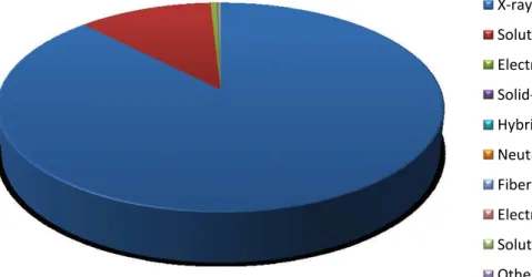
Hits % Experimental Method 72405 87,74 X-ray Diffraction 9417 11,41 Solution NMR 436 0,53 Electron Microscopy 51 0,06 Solid-State NMR 50 0,06 Hybrid 38 0,05 Neutron Diffraction 37 0,04 Fiber Diffraction 33 0,04 Electron Crystallography 32 0,04 Solution Scattering 23 0,03 Other 82522 Total hits
Table 1: PDB Experimental Method statistics (http://www.rcsb.org/pdb)
PDB statistics (Table 1 and Figure 1) show clearly that X-ray diffraction and Solution NMR contribute to the larger part of the solved structures. The gap between the two methods is essentially due to limiting molecule sizes that can be studied by the NMR and also the time required for the experiments. Nevertheless, this method has the advantage of not needing crystals. X-ray diffraction method requires protein crystal samples, which often are not easy to produce. We will discuss this point in Chapter I:2.2. Principles of Protein Crystallization. In spite of that X-ray diffraction has the advantage, with all technological and instrumental development (see 1.3. Crystallography and 3.2. Methodologies), of acquiring data rapidly, up to resolutions as high as 0.45 Å (PDB reference: 3NIR).
Figure 1: Experimental Method pie chart from PDB statistics (http://www.rcsb.org/pdb)
X-ray Solution NMR Electron Microscopy Solid-State NMR Hybrid Neutron Diffraction Fiber Diffraction Electron Crystallography Solution Scattering Other
1.3. Crystallography
With molecules exposed to X-rays, the scattered radiation contains precious information on molecules structure. Nevertheless, over 99% of the X-rays pass through the molecule without being scattered. So to emphasis the scattering signals, a large number of same molecules should be arranged in a well known spatial configuration. This arrangement of molecules constitutes what is called a crystal (Figure 2). The science related to the arrangement of molecules is called crystallography. It defines a crystal as a unique form of arrangement of molecules or a three-dimensional repetition of molecules creating a lattice.
Mathematical studies on crystal morphology showed a limited number of ways of arranging molecules within a crystal lattice. In 1845, Bravais1 concluded that the number of lattices is limited to 14 due to the symmetrical criteria, in crystalline structures. Thereby spatial configuration of crystals can be known.
Figure 2: Tridimensional Crystal (Cherrier, 2006)
In structural biology, single crystal X-ray diffraction technique is used to solve the structure of macromolecules. Nucleic acids and proteins are first produced in monocrystalline structures (see 2. Protein Crystallization) and then exposed to X-ray for diffraction
1
measurements (see 3. X-ray Diffraction). Processing of diffraction measurements lead to tridimensional structure of the concerning macromolecule. Myoglobin (PDB reference: 1MBN) was the first protein to have its tri-dimensional structure solved by X-ray crystallography, in 1958 by Kendrew1 (Kendrew et al., 1958).
Several major steps marked the history of evolution of X-ray crystallography. One of the most important one was the creation of large facilities, synchrotrons with high intensity X-ray beams and protein X-X-ray crystallography dedicated beamlines. Today more than 30 synchrotrons with more than 70 X-ray crystallography beamlines are available all around the world. This gives easier access to X-ray intense beams and makes experiments faster. Another major step in X-ray crystallography was cryo-cooling of crystals (see Chapter I:4.2. b) Cryo-protection and flash-cooling) for X-ray diffraction. Room temperature exposure of macromolecular crystals causes serious radiation damage to crystals. Thus, crystals perish into X-ray beam and diffraction patterns quality decreases rapidly to unexploitable. Cooling crystals help reducing radiation damage so that complete dataset for structure resolution can be collected from a single sample. A third considerable advance was automation of sample preparation, data collection and data processing procedures (see 5. Why high-through put crystallography). Complete high-high-throughput crystallography pipeline is the logical next step, which has been discussed widely by the crystallography community since few years. In this manuscript, few developments are made towards this ambition.
1 John Cowdery Kendrew, 1917-1997, was a biochemist and crystallographer who shared the 1962 Chemistry
2. Protein Crystallization
X-ray crystallography being the key to a rapid and high resolution tri-dimensional structure of macromolecules, the protein crystallization is a necessary step for it. Nevertheless, obtaining good diffraction quality crystals remains the major bottleneck to structure resolution. There are several parameters and methods improving the crystallization process, but there is no method of predicting the best conditions of good diffraction quality crystal growth for a specific protein. In the following macromolecular crystals are presented and crystallization principles and techniques for an optimum crystal growth are detailed.
2.1. Protein Crystals
Protein crystals are macroscopic objects composed of regular arrangement of molecules. Macromolecule crystals are grown in aqueous solutions in which the concerning protein is solubilized. Due to inter-molecular space in crystalline lattice, protein crystals contain from 27 % to over 78 % solvent (Matthews, 1968). Their dimensions are quite random and could vary from 5 µm to more than 500 µm and they can grow in rather any unpredictable shape (see Figure 3). Due to their content, dimensions and often their unstable equilibrium state, protein crystals are very sensitive objects to mechanical stress, humidity, temperature, etc.
2.2. Principles of Protein Crystallization
The crystal growth physics is a quite complex knowledge which today is highly advanced (McPherson, 1999; Ducruix et Riès-Kautt, 1990; Asherie, 2004; Vekilov, 2004; Veesler et Boistelle, 1999). Even though instrumental developments allow better controlling the kinetics of crystal growth (Budayova-Spano et al., 2007) nevertheless this knowledge is poorly controlled in mostly used and also in high throughput crystallization techniques. Thus crystallization still remains mostly experimental.
Here by a few key expressions are defined to better comprehend the crystallization process.
Supersaturation: This term refers to a solution that contains more of the dissolved material than could be theoretically dissolved by the solvent under the solubility amount (i.e. Solubility Curve, see Figure 4).
Metastable: It refers to a physical or a chemical stable state that could last long.
"This corresponds to the metastable zone, where the supersaturation level is too low for nucleation, so that no new crystals form in any reasonable amount of time."
(Budayova-Spano et al., 2007).
Nucleation: "A line of recent theories and simulations have suggested that the
nucleation of protein crystals might, ..., proceed in two steps: the formation of a droplet of a dense liquid, ..., followed by ordering within this droplet to produce a crystal." (Vekilov, 2004).
Crystal growth is mainly a result of precise molecular organization of a supersaturated solution in a thermodynamically adequate condition and favorable kinetics. In order to overcome very low molecular attractive force of protein molecules, highly purified and homogeneous protein samples are required for protein crystallization (Giegé et al., 1986). Despite, crystal growth could take over several weeks, whereas some could grow in only few hours.
Crystallization conditions could be related to numerous features, such as: protein concentration, temperature, solvents and their concentrations, pH, etc. In theory, to obtain crystals, the crystallization solution should evolve, with a controlled kinetic and temperature, towards a supersaturated state to trigger nuclei formation. The evolution of the
crystallization solution to the supersaturated state is related to both protein concentration and precipitant concentration. Furthermore, the evaluation of the supersaturated state through a concentration ratio1 defines the driving force2 for nucleation and growth (Veesler
et Boistelle, 1999). Once at supersaturated state and when nucleation points start to appear,
protein concentration would rather diminish to avoid numerous nuclei formation and also to enhance the crystal growth. The reduction of protein concentration to the metastable zone in the phase diagram induces slow crystal growth in order to let crystals reaching maximum degree of order in their structure (see Figure 4).
Figure 4: Crystallization phase diagram
In practice, the effective protein concentration is doped in solvents by the addition of precipitant agents such as salt (e.g. ammonium sulfate) or PEG (Polyethylene Glycerol). Thereby several techniques are used to reach the supersaturated state and favor crystalline
1
Supersaturation ratio where C and Cs are the actual concentration and the saturation concentration respectively.
2
Driving force is the difference between the chemical potential of the solute molecules in the supersaturated state (µ) and saturated state (µs) respectively: where kB is the Boltzmann constant, T the absolute temperature and the supersaturation ratio.
precipitation (see 2.3. Crystallization techniques). Nuclei formation induces protein concentration decrease. Depending on the initial protein concentration and the nuclei formation, the concentration should reach the metastable zone over the solubility curve (see Figure 4) were crystal growth could continue.
2.3. Crystallization techniques
As mentioned above, the key point in protein crystallization is to control the thermodynamics and kinetics of supersaturation evolution. Two major techniques are used: liquid-liquid diffusion and vapor diffusion, producing different kinetics of the equilibrium. In this manuscript both techniques are described with emphasize on vapor diffusion techniques which is the most commonly used methods allowing high throughput crystallization and thus the one used in this thesis studies.
a) Liquid-liquid diffusion crystallization
The diffusion is made, either through a direct liquid-liquid interface (Crystallization batch, Counter diffusion), either through a dialyze membrane.
Crystallization batch: This method is the oldest crystallization method. A precipitant reagent drop, of around 1 µL, is dispensed directly into a protein solution of the same volume. This brings instantly the solution to supersaturated state. The drop is covered by an oil (e.g. paraffin) to avoid evaporation. Hopefully nuclei formation and crystal growth will follow. This method is the simplest but not the most productive method.
Counter diffusion: The method uses small bore capillaries in which, first the precipitant solution of about 5 µL is dispensed. A volume of the protein solution is then added over and the tube is sealed with grease and kept vertically. The small diameter of the capillaries allows slow diffusing of the two solutions into one another, creating a continuous gradient of supersaturation. The supersaturation ratio decreases towards the bottom. This will allow the nucleation and crystal growth at different height of the capillary.
Figure 6: Counter diffusion in capillaries for protein crystallization
Dialysis: Many variation of dialysis technique for crystallization exist, but the most convenient and common one is the dialysis buttons. The protein solution is dispensed in a button covered with adapted membrane. Different dialysis buttons with different volumes and different membranes with different molecular weight cut off range are also commercially available. The membrane is held thanks to an elastic rubber ring. The button is thus plunged into precipitant solution, where the membrane avoids protein extraction and allows precipitant diffusion into the button.
b) Vapor diffusion
As shown in Figure 8, two different methods, but with the same vapor diffusion principle, are used: hanging drops and sitting drops. Crystallization drops of 50 nL to over 4 µL, containing a mixture of protein solution and precipitant are dispensed next to a reservoir containing larger volume of precipitant (25 µL to 1 mL). The whole is kept confined in 100 µL to few milliliter spaces. Natural vapor diffusion between the two solutions slowly evolves the concentration in protein mixture to an equilibrium state. This evolution of concentrations the crystallization drop in precipitant and in protein leads to supersaturation state and hence to the nucleation and crystal growth (Hampel et al., 1968).
Figure 8: Vapor diffusion crystallization techniques with hanging drops and with sitting drops
Crystallization drops can be dispensed on glass cover slides or sealing trays and are disposed over reservoir trays. A grease layer between the cover and the reservoir prevents evaporation, and so drops are hanging. Crystallization plates with 16 to 96 reservoirs are commercially available for hanging drops vapor diffusion method.
Figure 9: Greiner Bio-One 24 well crystallization plate for hanging drops
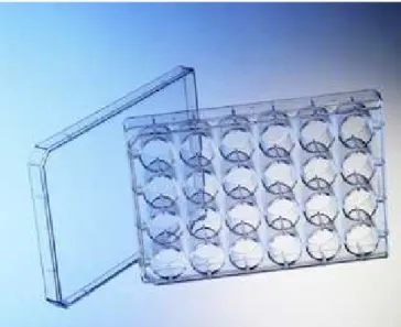
Special crystallization plates with few wells (1 to 3) per reservoir for sitting drops are used for vapor diffusion crystallization technique. Since automation of liquid dispensers, these crystallization plates are the most used in protein crystallography. In the last few years many crystallization robots and plates have been developed to reduce the volume of sample used for each crystallization drop and also accelerate the liquid dispensing. Nowadays robots can manage dispensing few nano-litter drop sitting drops on 96 well microplates (see Figure 10). A complete 96 well microplate can be prepared with these robots in matters of seconds, paving the way to high-throughput protein crystallography.
Figure 10: Greiner Bio-One 96 well crystallization microplates (with SBS standard geometry) for sitting drops
Once crystal growth has succeeded and protein crystal samples are available, they should be prepared for X-ray diffraction. Preparation steps are detailed in the following.
3. X-ray Diffraction
As mentioned above, X-ray diffraction represents the most contributive experimental method for structure resolution in structural biology. In order to present the possible improvements that can be introduced to the preparation procedures and the quality of collected data during crystallography experiments, the principles of this method and the different experimental methodologies are introduced.
3.1. Principles
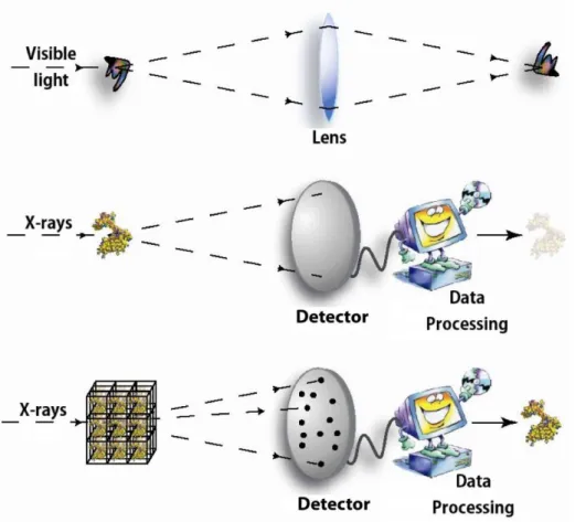
X-ray wavelength is adapted to observe atomic details, as inter-atomic dimensions are about 1 to 2 Å and X-ray wavelength is in the range of 0.1 to 1000 Å. Nevertheless, using X-ray for direct observation at the atomic scale is not possible, considering that the refractive index of X-ray is so small that an optic lens for X-ray microscope is impossible to make. Therefore, analysis of the atomic structure of macromolecules requires another method. An alternative solution is to collect the X-ray diffraction measurements from a single crystal (see Figure 11). By processing these collected data, we are able to deduce the atomic structure of the crystallized macromolecule.
X-ray diffraction is considered as a scattering technique. X-ray photons from an incident beam are reflected when encountering atoms of the exposed sample, giving birth to a scattered beam. As mentioned before, over 99% of the X-rays pass through the molecule without being scattered. So to emphasize the scattering signals, a large number of same molecules should be arranged in a well known spatial configuration, which is called a crystal. In 1912, Bragg1 discovered that precious information could be revealed by measuring the intensity and the angle of the scattering beam on a crystalline sample. Bragg law relates the incident wavelength to the scattering angle and the distance between atomic planes of a crystal lattice (see Figure 12). A discrete atomic model of a crystal in Figure 13 shows the distance d ngle as half of the angle between the incident and the scattered beam.
Figure 12: Bragg law
Moreover, Bragg discovered that reflected photons from the incident beam could interfere constructively (overlapping one another producing a more intense scattered wave) or unconstructively (neutralizing one another or decreasing the intensity of the wave) (see Figure 13). The results of these interferences of scattered beam are the spots observed on diffraction patterns. Crystals, as a three-dimensional periodic repetition of molecules, allow increasing the constructive interferences to give more intense spots and thus generate usable information for structure resolution.
Figure 13: Constructive (on the left) and deconstructive (on the right) interferences in X-ray diffraction of a crystal sample (Image from Wikipedia web site http://en.wikipedia.org)
1 William Lawrence Bragg, 1890-1971, discovered the Bragg law in X-ray diffraction in 1912 and was joint
The scattered X-ray from the crystal allows the measurement of a large number of Bragg reflections in a single exposure. A crystal lattice is three-dimensional, only a fraction of the crystal lattice points are in diffracting position at any given orientation of the crystal. Therefore, the crystal is also rotated through an angle of 0.1 to 2° during the exposure to bring more reflections to diffracting position. A diffraction pattern represents an instant image of the crystal. Thus, in order to be able to reconstruct the three-dimensional structure of the crystal, exposures at different orientations of the crystal are required. The crystal lattice has a rotational symmetry allowing limited orientation in diffraction data collection. Thus crystals with higher symmetry require fewer diffraction images to cover the entire crystal lattice.
A whole data set for a protein crystal contains several diffraction patterns and a diffraction pattern contains many reflections. The processing of these data to structure determination is a quite complex physical and mathematical knowledge which has made considerable advances in automation in the last two decades allowing high throughput data processing (Kabsch, 1988) and refinement to structure determination (Holton et Alber, 2004; Perrakis et
al., 1999).
3.2. Methodologies
The predominant method in scattering protein crystals is the frozen sample X-ray diffraction. Also a new method is gaining in importance for screening crystals and sometimes collecting dataset at room temperature, called in situ X-ray diffraction.
a) Frozen sample X-ray diffraction
Until two decades ago protein crystals were exposed at room temperature to X-rays. After the crystallization step of targeted proteins, crystal sample were sucked into micro-capillaries from their crystallization drops. In order to reduce the background scattering the mother liquid sucked with the crystal was removed from around the crystal in the capillary. Thus the crystal was exposed in the capillary to rays at room temperature. Even though X-ray diffraction is considered as non-destructive scattering technique, macromolecular crystals suffer in the X-ray beam due to radiation damage (Garman et Schneider, 1997). Due to the radiation damage induced to the crystal, only few diffraction patterns with good
quality scattered spots were exploitable. Experiments at 4°C showed reduction of the radiation damage and improvement of the quality of data collected. Later on, cryo-crystallography allowed scattering crystals at cryogenic temperatures below 140 K with very limited radiation damage and thus improvement of the quality of data collected, despite an increase of the crystal mosaicity. As a result, frozen sample X-ray diffraction has become the most common technique used in collecting protein X-ray diffraction data.
In this method, frozen samples are sat-up on a goniometer to allow rotating crystals for single wavelength rotation X-ray diffraction measurements. The goniometer axis is called the spindle axis, which is usually perpendicular to the beam axis. The spindle and the beam axis intersect at the sample position. The crystal has to be centered carefully on this position to avoid the crystal exiting the beam while rotating. This configuration in rotating crystals is considered as Kappa = 0° along with Phi rotation for the goniometer (see Figure 14). Accordingly samples are exposed to X-rays while rotating the crystal. Diffraction patterns are saved for every rotation step, classically from 0.1° to 2° but essentially 1°. Total angular sector to be collected depends on the symmetry of the crystal lattice.
Figure 14: Frozen sample X-ray diffraction set-up with Kappa = 0 and Omega rotation
Different strategies (Dauter, 1999) are possible in rotating the crystal and exposing the crystal lattice for X-ray diffraction. To have complete data of some crystals thus the orientation of the crystal or of the spindle axis of the goniometer could be changed (see Figure 15).
Figure 15: Goniometer Kappa 0 configurations in diffraction strategies, Kappa rotation, Omega rotation
b) Room temperature in situ X-ray diffraction
Today in macromolecular crystallography, crystals are more often prepared in drops dispensed in crystallization plates (see 2. Protein Crystallization). Each crystallization plate could contain 24 to over 380 drops. Depending on each protein, the drops volume, contents and concentrations, from 0 to hundreds of crystals could appear in the same plate. Sometimes the crystals formed in the drops are not made of the targeted molecules, but they are instead made of a molecule from the crystallization solution (e.g. very commonly NaCl or ammonium sulfate crystals). In order to analyze crystals before preparing them for frozen sample X-ray diffraction experiments, crystals could be diffracted in situ. With this technique, developed in 2004 on FIP-BM30A beamline at ESRF, crystals can be analyzed directly in their crystallization plates (Jacquamet et al., 2004). Further than the discrimination between protein and salt crystals, as mentioned above, diffraction patterns from in situ exposure could reveal precious information on the crystals: protein crystal or not, diffracting quality, diffracting resolution, mono-crystalline or poly-crystalline, point group, mosaicity, etc. Nowadays, this method is more and more used to screen crystallization plates for good diffraction quality crystals and is even quite automated (Bingel-Erlenmeyer et al., 2011).
Figure 16: Robotic in situ X-ray diffraction with G-Rob
Nevertheless, for in situ diffraction method, crystals are exposed among their crystallization solution and also the crystallization plate. This induces higher background scattering in the diffraction patterns comparing to frozen sample method. Furthermore, to solve the tri-dimensional structure of studied macromolecules, a complete diffraction dataset is needed. The large angular sector required for a complete dataset may be challenging too, considering the geometrical limitations of the crystallization plates and the rapid decay of the crystal at room temperature. Several crystals may be needed to achieve a sufficient completeness of data (see Chapter II: Crystal Listing for automated in situ crystal centering and data collection). In spite of all, the in situ method has grown in importance with the possibility to solve structures. This method is highly recommended for protein crystals hardly cryo-protected or cryo-cooled (see 4.2. b) Cryo-protection and flash-cooling).
4. Preparations for X-ray diffraction
Depending on the X-ray diffraction strategy chosen to analyze crystals, preparations are different. Even though in situ ray diffraction is still not as widespread as frozen sample X-ray diffraction, yet both methodologies are detailed due to the potential of the in situ X-X-ray diffraction crystal analysis.
4.1. In situ X-ray diffraction
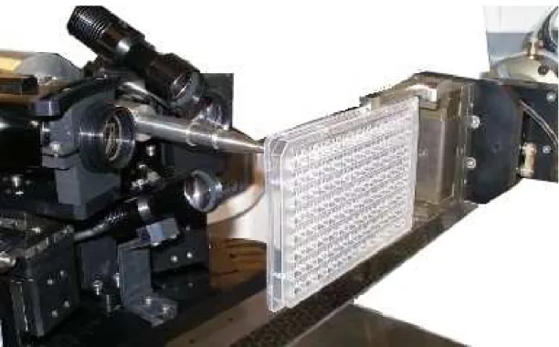
For crystals to be diffracted in their crystallization plates, the preparations should be done upstream the crystallization. Vapor diffusion sitting drop crystallization microplates1 are the most adapted to in situ diffraction, as their geometry enables holding plates vertically without mixing the crystallization drop with the reservoir solution (see Figure 17).
Figure 17: In situ X-ray diffraction in microplates
In order to reduce background scattering due to microplate's material, best crystallization plates with the lowest background scattering should be chosen. Depending on the geometry
1 Standard dimensions are defined for microplates by American National Standards Institute (ANSI),
and the material of micoplates, different scattering values are observed (see Figure 18). CrystalQuickTM X microplates show improved performance in this field with till about three times lower background scattering comparing to other classical crystallization plates.
Figure 18: Background scattering curves of different crystallization microplates in arbitrary unit measured at FIP-BM30A beamline at ESRF
With robots capable to collect data in situ, crystallization plate geometries should be adapted for oscillation around crystals without obstructing the incoming X-rays to the crystal and also the scattered X-rays by the crystal (e.g. CrystalQuickTM X plates allow ±40° rotation around crystals, see Chapter II:2.3. ).
After choosing best adapted microplate and crystallization, crystals are centered manually or through motorized human controlled instruments and X-ray diffraction data can be collected.
4.2. Frozen sample X-ray diffraction
Radiation damage in macromolecular X-ray crystallography is an age-old issue (Garman, 2010). The root cause of this damage is the energy lost by the beam in the crystal owing to either the total absorption or the inelastic scattering of a proportion of the X-rays as they
pass through the crystal. Cryo-cooling samples for X-ray diffraction show significant advantages in reducing the radiation damage by better preserving the crystal. Higher resolution data can more easily be obtained owing to the longer crystals order preservation and so collecting better diffracting quality data (Garman, 1999) and from fewer crystals for a complete dataset.
As for the frozen sample X-ray diffraction preparation of protein crystal grown in solution, freezing process is not straightforward. Crystals need to be transferred out of their mother liquid and prepared through different steps (see a) Harvesting). Additionally, collecting data at cryogenic temperatures could not only reduce the radiation damage but it can also reduce atomic movements and so contribute to higher resolution in collected data. As crystals contain from 27 to 78% solvent, the ice formation should be avoided. The ice formation of water molecules induces their volume expansion which damages protein molecules crystalline arrangement. Ice formation also induces crystalline water molecules that scatter X-rays, and so this is crucial to avoid. As a result, cryo-protecting solutions are diffused into crystals and fast cryo-cooling is managed (see b) Cryo-protection and flash-cooling) to turn water molecules into amorphous ice, with reduced volume expansion. Hence, as crystals are mounted on supports with transparent materials to X-ray, crystals can be exposed to X-ray for diffraction data collection.
The materials and methods used for each of these steps are described in the following.
a) Harvesting
This step concerns the transfer of crystals from their crystallization mother liquid into handy support for other preparative operations and X-ray diffraction. This task is more difficult than it seems as crystals are quite small, difficult to see and so fragile objects. The most common tool and method used nowadays is the use of micro-loops (Teng, 1990). When socking the loop into a liquid, a thin liquid film covers the loop by capillarity. The principle is to hang crystals into the liquid film on the loops (See Figure 19). Since few years, several commercialized loops in different material (e.g. Nylon and Kapton ) and dimensions (20 µm
Figure 19: Harvesting loops, Nylon CryoLoopTM from Hampton Research, Kapton MicroLoopsTM from MiTeGen.
Nylon and Kapton are respectively polyamide and polyimide materials with quite good
transparency features to X-rays (see Figure 20). Thus, these loops are used as crystal manipulators and holders for all the preparation operations, from harvesting to X-ray diffraction.
In order to improve the manual handling of these loops and to adapt them to goniometer heads, loops are mounted on pins which are plugged into caps (See Figure 21). Caps manufactured with a magnetic base can be easily mounted on magnetic pens to better handle loops and also on magnetized goniometer heads.
Figure 21: Loop + Pin + Cap + Magnetic Pen
In the last few decades these developments have made harvesting easier. In spite of all, this operation remains pretty difficult as crystals dimensions and fragility require accurate manual micromanipulation. Besides, crystallization drops states could worsen the difficulty of this task. Indeed, crystals are some time stuck to the bottom, or a thin layer of solidified solution covers the drop and many other complicated situations may be encountered. Consequently, harvesting crystals without damaging them is a challenging work.
b) Cryo-protection and flash-cooling
As mentioned above, the aim of protecting crystals followed by flash-cooling to cryo-temperatures is to prevent ice formation in crystals and also in loops' solution, for cry-temperature X-ray diffraction. Hereby we present how the addition of cryo-protecting agents and flash-cooling avoid ice formation in frozen aqueous solutions and so in crystals and mother liquid around crystals in the loops.
At atmospheric pressure, pure water melting temperature (Tm) is at 273 K, homogenous
nucleation temperature (Th) at 235 K and its glass transition temperature (Tg) is in between
130 K and 140 K (Rasmussen et MacKenzie, 1971). By lowering water temperature with slow cooling rates (few K.s-1), ice nucleation points will appear and allow crystalline rearrangement of water molecules (See Figure 22). By flash-cooling to lower temperatures
than its glass transition temperature, water molecules state will change to vitreous or amorphous ice by transiting ice nucleation zone. As the transition is done fast enough, no nucleation or crystalline arrangement appears. For pure water, the required cooling rates are ~106 K.s-1 (Brüggeller et Mayer, 1980). In the last few decades, numerous studies have been led to find best cooling rates possible in practice, with different cooling agents (Teng et Moffat, 1998; Walker et al., 1998; Kriminski et al., 2003). All studies agree in that 106 K.s-1 cooling rates range is unachievable. This explains the necessity of using the cryo-protecting agents. Indeed, mixing water with Glycerol, Ethylene Glycol or MPD can reduce the required cooling-rates to lower than 102 K.s-1 (Peyridieu et al., 1996 and Warkentin et al., 2006).
Figure 22: Phase diagrams of (a) Ethylene Glycol and (b) Glycerol at atmospheric pressure (Shah et al., 2011)
For cryo-protecting, crystals are generally soaked into a cryo-protecting drop, right after the harvesting step. Crystals are very often released into the cryo-protecting drop. So it is needed to transfer the crystal out the drop once again before proceeding to the flash-cooling. Unfortunately, cryo-protecting agents can also harm crystals. They can affect proteins solubility or cause crystal cracking or dissolution. At high cryo-protecting agent concentrations crystal structures are unluckily exposed to changes (Cobessi et al., 2005). Consequently, finding the optimum cryo-protecting solution is another challenge to the structure resolution at cryogenic temperature. This is of course one more reason to manage
in situ experiments, when feasible.
Most commonly cryo temperature elements used at atmospheric pressure to improve flash-cooling crystals are liquid propane/ethane, liquid nitrogen and gaseous helium and nitrogen
stream. Even though high pressure could improve cryo-cooling, the most common methods used are at atmospheric pressure due to the complexity of high-pressure process and instruments (Kim et al., 2005 and Thomanek et al., 1973).
Helium gas stream instruments can reach low temperatures of about 10 to 30 K. Open flow cryo temperature helium stream has been used for cryo-crystallography (Hanson et al., 1999). But helium remains expensive for random experiments. With liquid propane, quite good results have been obtained, nevertheless due to its inflammability high security precautions are needed. Propane is used rarely in very specific cases (e.g. flash-cooling in anaerobium incubators). Nitrogen gas (100 K to 120 K) and liquid (77 K) are highly popular cryo elements used in cryo-crystallography thanks to their availability, low cost and instrumental simplicity. In most cases, depending on crystals, 10 to 30% w/w Glycerol or Ethylene Glycol allows good quality flash-freezing with liquid or gas nitrogen.
For gas cryogenic elements, generally crystals on loop are exposed suddenly to the cryo temperature gas stream thanks to a shutter cutting the stream. For liquid cryogenic elements, the crystal on loop is plunged directly into the liquid.
Figure 23: Harvesting, flash-cooling and storage into liquid nitrogen thanks to Pin + Vial + Cap + Puck
Once crystals frozen, they can be stored in liquid nitrogen. To keep frozen samples at cryo-temperatures while transferring them, a cylindrical reservoir called vial is used to cover the cap keeping the loop with crystal in liquid nitrogen (see Figure 23). A magnetic ring at the
top of the vial maintains the vial on the cap. Vials among caps are stored into packs which are disposed into Dewar1 flasks.
Many different pucks for vials among caps storage have been developed, to facilitate carrying or shipping frozen samples from laboratories to synchrotrons and also for automated sample transfer to goniometer for diffraction measurements, as described in the following section.
c) Diffraction measurements
Crystals can be diffracted whether in situ at room temperature in crystallization microplates (Jacquamet et al., 2004) or by preparing them for frozen sample diffraction at cryo temperatures. For both the aim is to collect as much as good quality data possible in order to be able to solve the structure with the highest resolution and completeness through data processing, structure model building and structure refinement.
Figure 24: Manual mounting/dismounting frozen sample on MD2 goniometer in K (Macromolecular crystallography beamline at BESSY II, Berlin)
1 John Dewar, 1842-1923, invented Dewar flask, a reservoir with good thermal insulation, at Cambridge
Frozen samples can be mounted on goniometer heads manually (see Figure 24). The goniometer heads are magnetized to hold caps once in touch with the cap's base. The vial plus its cap is presented to the goniometer magnetized head. This maintains the cap in position. Then vial full with nitrogen liquid is removed. A nuzzle blows the cryogenic temperature (100 K to 120 K) nitrogen gas stream towards the sample. This keeps the sample frozen during the whole experiment. Generally, a microscopic view of the sample calibrated with the beam position and two translations on the goniometer head allows centering the sample accurately into the spindle axis and so into the beam.
X-ray sources combined with optics and detectors, play an important role on the achievable resolution and also on experimental time. The higher the beam intensity, the less exposure time is needed for intense spots at high resolution on diffraction patterns. At the other hand, electronic detectors are capable of high-throughput data collection. Today's microfocus beamlines at synchrotrons combined with highly performance electronic detectors, enable collecting a complete dataset in even less than a minute. In order to follow this rhythm and to fully benefit from these facilities, automating the sample preparation and manipulation steps are required.
5. Why high-through put crystallography
5.1. Stakes and needs
In the last two decades, interest in atomic structure of proteins continuously increased. One of the most contributing steps has been the use of anomalous signal from selenium, with selenomethionine, and the MAD (Multi-wavelength Anomalous Diffraction) method to solve the phase problem (Hendrickson et al., 1990; Weis et al., 1991). Moreover, in terms of means, progress in chemical and molecular biology have increased the possibility to produce more and more proteins with greater cadence. With genome sequencing developments, the number of proteins of interest has risen. Besides, the number of applications of protein structures is also increasing from the classical drug design to structure-based drug design (Williams et al., 2005; Grey et Thompson, 2010), with pharmaceutical companies investing on macromolecular crystallography beamlines (e.g. beamline X06DA at Swiss Light Source) and plant engineering. Thus, the number of proteins to study continues to grow and the need of faster structural studies and so high throughput structural biology has become a necessity.
5.2. Responses
With arisen demands in structure resolution, more and more synchrotrons with macromolecular crystallography dedicated beamlines have been built world widely. The X-ray beam intensities along with instrumentation developments allow automating and accelerating increasing experiments. In the near future, intense synchrotron beams combined with high-performance electronic detectors could achieve a complete dataset collection in only few seconds.
5.3. State of the art in automation a) Crystallization
As mentioned before, crystallization robots can achieve very rapid and accurate liquid dispensing. They can manage dispensing a whole 96-well plate with crystallization drop of 100nL in less than a minute. Therefore, crystallization assays become less time consuming and require now reduced amount of protein. Large screening assays are now possible, increasing the potency to obtain diffracting crystals.
b) Sample changers and electronic detectors
About two decades ago, to save one single diffraction pattern with electronic detectors, took more than 15 seconds. Today, higher resolution detectors have dead time of few milliseconds.
Many attempts have been made in developing automated frozen sample changers that transfers crystals from a liquid nitrogen storage Dewar to a goniometer. First system developed was the SAM system at Stanford Synchrotron Radiation Laboratory (SSRL). Rigaku has commercialized a robotic system developed at Abbott laboratory in the name of ACTORTM, since 2001. The Automounter has been developed also in early 2000 at Berkeley at ALS. Other systems were born in Europe as well at the same time, such as the SC3 system. This system built at EMBL at Grenoble in France and commercialized by Maatel. Two robotic systems based on 6-axis robotic arms were also built in Grenoble at ESRF, at FIP-BM30A beamline: Cryogenic Automated Transfer System (CATS, commercialized by IRELEC) and G-Rob (commercialized by NatX-ray). All these systems contributed to automating X-ray diffraction experiments and thus stimulate the speed of experiments.
c) Data processing and structure resolution
With the computing powers increasing in hardware and also software developments for data analysis (Kabsch, 1988; Leslie, 2006), structure resolution has been quite simplified. Software as Elves (Holton et Alber, 2004) is able to go from data processing to refinement. Using automatic procedures, Phenix (Adams et al., 2010) can handle for example anomalous data to find the heavy atom positions, calculate and improve the phases, in order to rebuild and refine the structure, while ARP/WARP (Perrakis et al., 1999) can build and refine the structure. With these hardware and software available on beamlines and also in laboratories, structures can come through in few hours, comparing to two decades ago when same tasks took months or years.
5.4. Missing steps in automation
In structural biology, from genome sequencing to structure resolution, almost all major steps has been automated, increasing the output of this science. Yet few essential steps remain manually operated.
Firstly, for in situ diffraction crystals have to be centered one after another. Knowing the high number of crystals that are needed to be centered in a row for screening, this step forms the bottleneck of a fully automated procedure. As in situ diffraction in microplates has shown its importance in screening crystals and even collecting complete datasets, no developments have been reported to fully automate this process. In chapter II of this manuscript, a new system completing fully automated pipelines for in situ analysis of crystals in screening microplates and also data collection for structure resolution is presented.
Secondly, as for the frozen samples, the preparation steps such as harvesting, cryo-protecting and flash-cooling remain manual and critical to high-through put crystallography. Many developments have been reported in the last few years in attempting to automate crystal harvesting and also cryo-protection and flash-cooling of crystals with more or less complete and adapted systems (see Chapter III:1. Introduction). In spite of all, these systems didn't succeed in filling the gap for a fully automated macromolecular crystallography pipeline. In chapter III of this manuscript, a new system (REACH: Robotic Equipment for Automated Crystal Harvesting) capable of harvesting protein crystals thanks to a micro-gripper, cryo-protection and flash-cooling is presented. The setup developed is integrated to the beamline FIP-BM30A for direct data collection or transfer on loop and storage into liquid nitrogen Dewar by local or remote users.
Chapter II: Crystal Listing for automated
in situ
crystal centering and data
collection
As one of the two major developments during my PhD, the Crystal Listing allows achieving fully automated in situ crystal centering and data collection for samples in microplates. Based on image processing crystal centering software, this function can be easily adapted to any in situ X-ray diffraction apparatus. Thus another step forward has been made towards high-through put macromolecular crystallography. This work has been clearly a result of developments, studies and experiments led during my PhD. The mechanical, automation and software developments of this system and also the assessment experiments have been lead and realized as part of my PhD under supervision of Dr Jean-Luc Ferrer with some technical contributions of coauthors. As for X-ray diffraction data processing, data clustering and structure refinement and resolution, they have been managed majorly by Hugo Lebrette and also by Dr Jean-Luc Ferrer. The following scientific report has been submitted to Acta Crystallographica section
D, on 1 August 2012.
"You gotta be pretty desperate to ... (do) it with a robot."
Crystal Listing for automated crystal centering
and in situ X-ray diffraction data collection
Yaser Heidari1, Hugo Lebrette2, Xavier Vernede1,2, Pierrick Rogues3, Jean-Luc Ferrer1,4
1 Institut de Biologie Structurale Jean-Pierre Ebel, Groupe Synchrotron; Commissariat à l Energie Atomique et aux Energies Alternatives, Centre National de la Recherche Scientifique, Université Joseph Fourier; F-38027 Grenoble cedex 1; France.
2 Institut de Biologie Structurale Jean-Pierre Ebel, Groupe MetalloProtéines; Commissariat à l Energie Atomique et aux Energies Alternatives, Centre National de la Recherche Scientifique, Université Joseph Fourier; F-38027 Grenoble cedex 1; France.
3 NatX-ray; 38400 Saint Martin d'Hères; France.
4 Correspondence; Email: jean-luc.ferrer@ibs.fr; Phone: +33 4 38785910; Fax: +33 4 38785122
Abstract
As High Throughput Protein Crystallography has earned its importance in crystallization platforms, the need to develop and invest in adapted and automated equipments for crystal analysis has become essential. The trend today is to use the smallest sample amounts to screen the highest possible number of conditions but it often leads to the production of very small crystals. Robots have been developed to reduce the time spent in preparing crystallization solutions and also in screening crystallization plates. Crystallization microplates have been conceived with various geometries to improve the output. Therefore the crystals to be analyzed need to be harvested, cryo-protected and flash-cooled which are quite challenging steps, as the crystals' reaction to these delicate operations is unpredictable. In situ X-ray diffraction analysis has become a valid option for these operations and a growing number of users apply it for crystal screening and also to solve structures. Robots and improved crystallization plates facilitate the in situ analysis. Nevertheless, because of radiation damage at room temperature, a large number of crystals have to be analyzed to obtain a complete dataset by merging data. In this high throughput approach, centering crystals automatically relative to the beam represents the bottle-neck of
instruments to define local geometry coordinates for each crystal in the plate for an automated crystal centering into the beam, in situ crystal screening and data collection.
1. Introduction
To optimize the study of protein structures using X-ray crystallography, it is crucial to improve the X-ray diffraction data quality. So far, the commonest method remains cryo-crystallography, by mounting and flash-cooling the protein crystals in loops (Teng, 1990). Nevertheless, crystallographers need to screen their crystals to select the best ones regarding their diffraction quality and resolution (Bingel-Erlenmeyer et al., 2011). This selection step is time-consuming because it requires to mount, cryo-protect and flash-cool each crystal. Furthermore, many macromolecular crystals and particularly membrane protein crystals get damaged by the cryo-protecting and flash-cooling procedure applied before X-ray data collection. In this context, room temperature in situ X-ray diffraction plate screening represents an attractive alternative approach (Jacquamet et al., 2004). In the last few years, manual and automated systems for in situ X-ray analysis have been developed, such as PX Scanner (Agilent Technologies), jig (Hargreaves, 2012) and Cryogenic Automated Transfer System (CATS) (Ohana et al., 2004). However, many experimental features in current X-ray in situ analysis are not optimized. Firstly, because a part of the crystallization plate and the crystallization drop are exposed to X-ray along with the crystals, a high background X-ray scattering is generated affecting the quality of the diffraction data. Secondly, a large number of crystals is often needed to complete the dataset as radiation damage limits the exposure time of each crystal.
Here, we report the use of a new crystallization plate called CrystalQuickTM X (Bingel-Erlenmeyer et al., 2011), made of a specific material and with a geometry that reduces background scattering compared to other commercially available crystallization plates. Furthermore, in order to automate crystal centering for in situ diffraction analysis, we also report the development of a procedure we called Crystal Listing. With this method the user can create lists of crystals selected in crystallization microplates and can launch automated crystal centering and X-ray data collection. This system has been developed at the FIP-BM30A beamline at ESRF and has been tested on the G-Rob home laboratory facility of Professor Cole at Ecole Polytechnique Fédérale de Lausanne (EPFL). Our approach may have a general application because it can be easily implemented on beamlines equipped with in