HAL Id: in2p3-00996667
http://hal.in2p3.fr/in2p3-00996667
Submitted on 23 Mar 2020
HAL is a multi-disciplinary open access
archive for the deposit and dissemination of
sci-entific research documents, whether they are
pub-lished or not. The documents may come from
teaching and research institutions in France or
abroad, or from public or private research centers.
L’archive ouverte pluridisciplinaire HAL, est
destinée au dépôt et à la diffusion de documents
scientifiques de niveau recherche, publiés ou non,
émanant des établissements d’enseignement et de
recherche français ou étrangers, des laboratoires
publics ou privés.
Beam tuning and stabilization using beam phase
measurement at GANIL
A. Chabert, F. Loyer, J. Sauret
To cite this version:
A. Chabert, F. Loyer, J. Sauret. Beam tuning and stabilization using beam phase measurement
at GANIL. Tenth International Conference on Cyclotrons and their Applications, Apr 1984, East
Lansing, United States. pp.559-562. �in2p3-00996667�
F«5"V o
z~j 83
^
BEAM TUNING AND STABILIZATION
USING BEAM PHASE MEASUREMENTS AT GANIL
A. CHABERT, F. LOYER, J. SAURET
and Operation Group
GRAND ACCELERATEUR NATIONAL D'IONS LOURDS
BP 5027 HO21 CAEN CEDEX (FRANCE)
V
r
GANIL. A84.08
BEAM TUNING AND STABILIZATION USING BEAM PHASE MEASUREbENTS AT GANIL A. CHABERT, F. LOYER, J. SAURET and Operation Group
GRAND ACCELERATEUR NATIONAL D'IONS TOURDS BP 5027 14021 CAEN CEDEX (France;
SUMMARY
Owing to the great sensitivity of the bean phase to the various parameters, on line beam phase measure-ments proved to be a very efficient uay of tuning and stabilizing the beam of the multi-accelerator complex. We recall the system which allows to obtain the diffe-rent kinds of accurate measurements we need and describe the main applications ;
- tuning process (buncher and SSC'l RF phase determination, setting of the required radial beam phase law in the SSC's)
- stabilization of the beam by loops, the basic principle of which being to keep constant the beam central phase all along the machine by adjusting RF voltages or magnetic fields.
Feedback loops arc described and comparative results wiLh and without feedback are given.
INTRODUCTION
CANIL is a cascade of 3 cyclotrons (Fig. 1) : a compact injector II followed by 2 separated sector cyclotrons SSCI and SSC2 with a stripper in between. The beam transfer line LI includes the buncher Rl ; in L2, the stripper is polarized at Vst.
U ; ~ 35m L 2 : ~ tOm 13 *v 15m Buncher /20m Stripper " * i — i Il — * R l } Vn SSCI
+."
VSTLoop 3 \-s Loop 1 Loop 4. V_^ Loop 2
Fig. I. Lao out of GANIL with the beam phase probes
(PP) and the loops.
Among the essential aspects of the GANIL operation are first the tuning of the RF cavities (phase and voltage) and of the SSC radial field laws, second the stabilization of the beam obtained at the end of the tuning procedure. Measurements of beam central phases along the machine is one of the most powerful way to perform these two requirements.
I. BASIC PRINCIPLES FOR TUNINC AND STABILIZATION
- 6B/B, in fact Sl/1 < I 0- 5 (with slow variations
much greater) and accounts for :
f= 0.3" in II -> SW/W = 1.5 I0"s
6cpo(N) o -2TthN6B/B< » 1.7* in SSCI -> 6H/W » 4.5 10"* 1= 3.2° in SSC2 -> SW/W « 1.6 10"' In the SSCs, the 6B effect is ich greater than -the 6V one ; it is the opposite for I. There from, the
idea of locking the SSC mean field to the variations 5(ijiOut _ ^in) 0£ the differ mce between the input and
output beam central phases in order t~ stabilize the phase law i|>*(N) (loops I and 2, Fig. .
I, ? Phase ''•bl.Htg in_traos|er_ Hnes_. Variations of <p*-n defend-on thë" variâ"tTons~o7 thë" ë"netgy and of the
path of tha central ion in the transfer line preceeding a SSC !
6W. <bin o k
«4-
250*/m in LI (modified by Rl) 70° /m in L2 20° /m in L3Effects of the field stability in th transfer line dipoles is quite negligible.
Two ways of controlling <fin may be u---à :
- to lock the RF phases $ of the cavities -J the beam central phase 4>in* this is possible due to the large
energy acceptance of the SSC's. This method was pre-viously applied but does not give very good results
(possible divergence).
- to keep constant independently $ and $*-n against an
external reference (the II RF phase) ; this means to keep energies constant.
In the GANIL RF cavities 1, $ is stabilized within
O.I* and we have then to stabilize $i-n.
For SSCI we chose to stabilize $\n by acting on the
I! RF voltage (loop 3, Fig. I). It would have been possible to lock Vj- on $£? measured in front of Rl : ir fact this loop was also tested and gave good results,but it appears to be aore global and convenient to use 4 in.
Concerning SSC2, it would be possible to lock V, on <j>£n
but we have preferred to act on Vst. This is much easier and takes account in a global way of the <5W variations at the SSCI output as well as of those due-to the stripper (loop 4, Fig. I).
For the moment no attempt was made to stabilize $ in L3, acting on the RF voltage V2, but such a loop is not excluded.
2, BEAM CENTRAL PHASE MEASUREMENT PROCESS
1 • l_R.£di.a.I £n£sl I3" in_a_sJLc• Adjusting the main
field level and the trim coil currents we obtain a predetermined radial phase law :
,theo .„. .in .o .„s
<f> (N) » $ + $ (N)
which can present various patterns (complete isochro-nism, phase compression . . . ) . After being tuned (c£. S3) this phase Law has to be maintained stable.
Beam stability is affected by variations of : - the RF voltage V and phase * of the RF cavities. - the radial phase law which depends on the stabi-lit> of **••* (function of what has happened before _the cyclotron) and on the law <J>°(N) (related mainly to the stability of the field level)%
Typical values are :
- ÔV/V < lO-" which gives cW/w < 10"" (sparking
considerations excluded)
To achieve beam tuning and stabilization with the required accuracy, the following beam phase measurement process has been davelopped 2 3.
2.1 P_roJbe ^o£atior.. Beam phase measurements are perfor-med : ~" ~" ~~
- inside each SSC. using IS pairs of capacitive probes» to tune the isochronism. These probes, loaded by 50 ohms, are located along a valley axis ; an extra UHF target, fixed on a movable radial yoke probe, allows the same phase measurements but turn by turn,
- along the beam lines, using B capacitive high impédan-ce probes. In particular, S of them are used (Fig. I) : . at the SSCI input (PP3) to tune the Rl buncher and SSCI RF phases and to stabilize the beam phase at the
SSCI input ; :
. at the SSC2 input fPP8) to tune the SSC2 RF phase
and stabilize the beam phase at the SSC2 input ; . at the SSC'si input (PP3 and PP8) and output (PP5 and PP10) to-stabilise their magnetic field ;
. at the Rl input (PP2) to calibrate phase measu-rements.
2.2 Measurement £rincip_l£. Phase measurements are made between the second harmonic of the probe signal and the double frequency II RF voltage.
Two types of measurements are used :
- Absolute measurements giving the beam central phase : . „ -1 ,Y - Y o . A A
* -
t a n (x ^ n t o >
+*o
(X, Y) being the probe signal components with beam and (Xo, Yp) without beam; fa " 4| + <frj comes from the electronic devices ($|) and the transmission cables ($2)* $1can DC known from phase measurements of a
reference signal with each electronic device and $2 from the beam phase measurement on PP2 where the beam phase is known when the RI RF phase is correctly tuned. - Relative measurements which give as t function of time» the phase variation H • Y/X and the beam inten-sity X when Y is small. A delay line makes Y • 0 at the beginning of measurements.
2.3 llanlwaxe. Figure 2 shows the analog electronic de-vice and the associated digital hardware for either the beam line probes or the 15 pairs of SSC's probes.
<S^>
Fig. 2. Seam phase measurement device block diagram.
Phase detection is performed by analog multiplying the processed probe signal (SHF) by the reference signal (R2F) to give X and by the 90* out of phase reference signal to give Y. The input level range of the phase detector is 25 dB. With a variable gain amplifier ahead, this range is raised to 75 dB.
The analog outputs (X, Y, Y/X, NIV) are synchroni-zed with the beam cycle by a sample and hold circuit.
This whole device is connected to the CAMAC inter-face which is controlled by an autonomous crate control-ler JCAM 10 equipped with an Intel 8080 microprocessor. This controller is linked to a local console for use in stand alone mode or to the main CAMAC loop for use on line with the main computer MITRA 125 and the operation console.
between the main computer and the process tasks. Procès^ tasks perform the following specific actions : initiali-zation (checking, rejection filter tuning), absolute and relative measurements (amplifier gain and delay line tuning, data acquisition with different options).
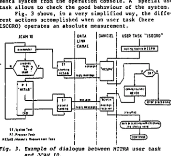
The MITRA 125 general software, named GANICIEL *, takes care of the dialogue between the JCAM 10 and the MITRA user tasks which operates the beam phase measure-ments system from the operation console. A special user task allows to check the good behaviour of the system.
Fig. 3 shows, in a very simplified way, the diffe-rent actions accomplished when an user task (here ISOGRO) operates an absolute measurement.
GANICIEL > USER TASK "ISOGRO*
Fig. 3. Example of dialogue between MITRA user task and JCAM 10.
2.5 Ac^ua>l_pe_rf_orma_n£es_, In both SSC's the sensitivity
of the 15 pairs of probes allows a resolution better than I* for 1 enA beam (equivalent bandwith : 10 Hz). So, the isochronism can be tuned with a beam intensity ranging from 1 enA to 10 eLiA. A better resolution is obtained with averaged measurements.
In beam lines, the probe signal is proportionnai to W~l/2, Resolution as a function of the beam electri-cal intensity is given in the following table for a bandwith of 10 Hz which is used in the absolute measu-rements and in stabilization devices :
Beam line9 0.1* O L 1 L 2 L 3 10 - 30 enA 50 - 100 enA 200 - 500 enA 1 5 20 -3 enA 10 enA 50 enA The stability is about 0.1° per day and the accu-racy of absolute beam phase measurements is :
0.2* between SSC probes 1° between beam line probes 3* between any probe and II RF
Figure 4 shows an example of the output signals of a phasemeter. Beam Cycle
ISSSSISSïii
1'""
TTLI!
2.4. Software. The JCAM 10 software is written so as a mini-monitor manages system and process tasks. System tasks are the software interface, via the CAMAC loop,
Output signals of the PP8 phasemeter with a 500 enA Ari6+ beam.
3. TUNING PROCEDURES
3.1. Jluncher ItF_pJia£e_adju.stment_. The method is based on the fact that the"~central beam energy must not be affec-ted when particles cross the buncher. So the beam line LI is first tuned* the buncher being off, and the cen-tral beam phase is measured on PP3. Then the buncher is turned on at its nominal voltage and its RF phase is tu-ned until the beam phase becomes the same as previously. 3.2. S_SC/£ RF_pjias_e_de_t£rmi£a£io_n. The method consists in reproducing the" same phase shift between the beam and the SSC RF phases as those already obtained from a pre-vious good tuning. A specific task measures the absolute phase .between the beam on PP3 (or PP8) and the II RF using the method previously described to maki an abso-lute measurement with calibration by meaauring the beam phase on PP2. Then, using data obtained from a previous good tuning, the Cask computes the SSCI (or SSG2) RF phase relative to the II RF.
The RF phase * determinated by this method is accu-rate enough to inject the beam into the SSC and to adjust the isochronism. The fine tuning of 4 is done by observing the beat turn separation near the extraction or better by minimizing the energy using the spectro-meter located at the entrance of experimental areas. 3.3. Field £0£*«£ions_ in£id^e_tJie_j3SC_!_s. Using the beam
central"~phases measured alon"g thVaxiT of a valley using the 15 pairs of capacitive probes, an interactive rou-tine ISOGRO has been developped to automatically achieve the isochronisn or any given beam phase law. The algo-rithm used to compute the field corrections and the user task diagram were previously described . In this paper» we report the main improvements.
Using the precalculated values of the main and the trim-coil currents, the various beams are accelerated roughly to a radius of 2 meters. After one adjustment of the main coil current as computed by ISOGRO (about 5.10~4) these beams reach the extraction radius and a maximum deviation of =« 20 degrees of the beam phase from the contemplated one is then usually measured.
The field gradient correction procedure, based on a least square method, has t:een now tested for a wide range of energy and the isochronous field is reached within ± 2 degrees with only 2 or 3 iterations on the trim-coil currents. The isochronization procedure inclu-ding beam phase measurements, calculations and power supply setting takes about 15 minutes. Figure 5 shows ' the results obtained in the case of an oxygen beam acce-lerated in SSC2 at the energy of 95 MeV/A, which corres-ponds to our maximum y,
•ÏS0C2 42 JIESUtt MUSCS CENTRALES VALLEE CSS C2.BIH.rC
31 NOV 1913 •• UK* 23M TRUITETïEJUÎ flIV 110
MENIERE some» i icanjcjtc some» is DCG forrnanc+ 5
$ , t4l».l
!!;!
- 21.S • - 21.1: I ! J . »
- ! « . : • • - 31.S. • — 1 . 1 i a-¥
's?fc»
HI « • JIS»
51) +m
*
411*
411*
471»
4C4 • 4(2=î±=5=î±^=;!ïïTiaî
The whole p r o c e d u r e h a s t o b e done o n l y once f o r each c a s e ( i o n o r energy) and t h e f i n a l t r i m c o i l c u r -r e n t s o b t a i n e d e n s u -r e a good -r e p -r o d u c i b i l i t y of t h e m a g n e t i c f i e l d f o r a n o t h e r run u s i n g t h e same beam. The computer code i s used i n o p e r a t i o n t o a d j u s t t h e main c u r r e n t w i t h i n an a c c u r a c y b e t t e r t h a n 10"-'. As thi beam phase d e v i c e i s n o t d e s t r u c t i v e i t i s a l s o o f t e n used t o s u r v e y t h e s t a b i l i t y of t h e m a g n e t i c f i e l d .
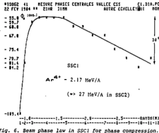
The o n - l i n e code ISOGRO can f i t any p h a s e law i n t r o d u c e d i n d a t a . F i g u r e 6 g i v e s an example of an improved e x p e r i m e n t a l phase law i n SSCI used t o p r o v i d e bunch l e n g t h c o m p r e s s i o n and o u t p u t e n e r g y i n s e n s i t i v e t o s m a l l f i e l d l e v e l v a r i a t i o n s .
•1S0G2 U MESURE PHflSCS CENTRALES VALLEE CSS CI.Dlft.PC 22 FEV U84 • • 21KR 11I1N AUTRE ECHELLEîBlI HON
- 5».?
- (I.I
- *7.l
Fig. 5. Beam central phases measured during the
isochxo-nization process : 95 MeV/A oxygen beam in SSC2 :
• with precalculated trim-coil currents i after one iteration on trim-coil currents « after two iterations on trim-coil currents
Fig. 6. Beam phase law in SSCI for phase compression.
4. BEAM PHASE STABILIZATION DEVICE 4.1. Futic£i£nal_desc_riptiop., The 4 beam phase stabili-zation devices are those presented previously (Fig, 1).
Figure 7 shows as an example the typical block-diagram of loop I and 3 devices made in the following way :
- the phase probes and their phasemeter units (Fig, 2) give the beam phase variation signal £<f>, the beam intensity X and its status in the relative measurement mode.
- Che signal processing unit (Fig. 7b) transmits 6<p
from the phasemeter to the control unit when the beam and the phasemeter are correct : <S<fp - 6$. When the beam behaviour becomes unusual (intensity too low or tc high), this unit sends to the control unit the memorize phase signal detected before (Fig. 8 ) . If 'the beam behaviour keeps bad too long, the unit makes £<J>p « 0 ar informs the control unit by the signal 0 K. At present, the waiting time T is 10 s long but it can be stretched up to a few hours if necessary.
- the control unit (Fig. 7 c) establishes the loop with the required transfer function. The loop gain is about 10, thus the beam phase shift is devided by 10, The bandwith is 10 Hz and will be possibly increased for loop 3 and 4 only, loop 1 and 2 bandwiths being limitée by the magnetic field response.
Procedure for users is the following : - phasemeters operating in relative measurement mode - loop tuning with the help of a zero detector to get a null correction (SC » 0) and loop switching on - if the correction signal SC is too high, a level alarm requests the operator (and later the computer as a future development) for a better tuning of either the SSC magnetic fields for loops 1 and 2, or the injector RF voltage for loop 3, or the SSCI RF voltage for loop 4 in order to get approximately a zero correction signal (SC = 0)
and the correction signal is null (SC • 0)
- when the beam failure disappears, the operator can set on the loop again with
with a new one.
> I* Loops ON -the previous beam tuning or
I t , M *
t
r
rtf?
1
G
lit!" "
ris'
• 7 0 -I EKJUISHCEWKtvM
y
MilFig. 7. a} loop i and 3 devices block-diagram b) signal processing unit
G} control unit 50 Ris
WWW
/u*k* Mrs
• ii •••••«'ijprjiaSSSSHf
-Beam Failures-' 3V/divfij. 8. Two examples of 5$p * o"<J> memorized" during
a beam failure.
4.2. Performances_in o_P«jitJLen_. Loops 1 and 3 have wor-ked £or~*a few months and" Toop~~4 has just been turned on.
In operation» these beam phase stabilization systems have two functions :
- first, they make monitoring more confortable. Without stabilization, one have to watch the beam phases conti-nuously and to retune the parameters as soon as a beam phase shifts too much (= !°) in order to keep a constant beam. This is particularly important during the early days of a run (for instance, SSC magnetic fields may
shift up to 5.IO"3 during the first two days). With
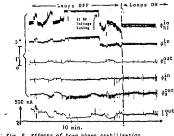
stabilizations, operators have to act only when a level alarm requests them ; otherwise the beam is always-correct. Fig. 9 shows an example of beam phase without stabilization (it has been necessary to retune Vj|) and with stabilization (loops I, 3, 4 only).
- second» they allow to keep optimal beam characteris-tics and especially beam central energy.
[•'«/^"liTv-s,!
10 nun.
Fig. 9, Effects of beam phase stabilization.
CONCLUSION
The phase lock system developped for the GANIL multiaccelerator complex keeps constant central beam phases, i.e. energies, hence the ion path. Beam charac-teristics on targets are then well defined and stable. The strong dependence of phase on machine parame-ters makes this method very accurate, Machine parameter chosen for control prove to be very efficient, conside-ring the results, although they are not always exclusi-vely responsible for the phase shifts. More experience and studies would be necessary for a still better under-standing and control of the beam, in particular on the point of view of the reproducibility of the initial set tings. In principle, beam central phase values, all along the machine must be the same for the whole range of particles accelerated in GANIL with a given set of harmonics.
References
1. A. Joubert et al., "Hain Results on the RF Amplitude, and Phase Regulation System in Operation at GANIL, this conf.
2. F. Loyer et al., "Main Beam Diagnostics at GANIL",
Proc. of the 9C n Int. Conf. on Che Cycl. and their
Appl., CAEN (France), Sept. 1981.
3. J.M. Loyant et al., "The Computerized Beam Phase Measurement System at GANIL", Proc. of the Conf, "Computing in Accelerator Design and Operation", West-Berlin, 1983, to be published.
4. M. Promé et aî. "The operation of the GANIL control System", this Conf.
5. J. Sauret et al., "Magnetic field Setting and Automatic Isochronization in the GANIL SSC's", Proc
of the 8t h All. Union Conf. on Charged Part. Accel.
Tome 1, Protvino, USSR, Oct. 1982.
6. A, Joubert et al., "Status Report on the GANIL Facility", This Conf.