Design for Automation in Manufacturing Systems and Processes
ByJuan Stefano Ezolino
Bachelor of Science in Mechanical Engineering Northwestern University, 2010
Submitted to the MIT Sloan School of Management and the Mechanical Engineering Department in partial fulfillment of the requirements for the degrees of
Master of Business Administration and
Master of Science in Mechanical Engineering
In conjunction with the Leaders for Global Operations program at the Massachusetts Institute of Technology
June 2016
C2016 Juan Stefano Ezolino. All rights reserved.
The author hereby grants to MIT permission to reproduce and to distribute publicly paper and electronic copies of this thesis document in whole or in part in any medium now known or
hereafter created. Signature of Author: Certified by: Certified by: Accepted Accepted b
Signature redacted
M6h 4L EngKineering Depp mient, MIT Sloan School of Management -,-7PVM5/5/2016
Signature redacted
Thomas Roemer, Thesis Supervisor Director, Leaders for Global Operations Program Senior Lecturer, MIT Sloan School of Management
Si nature redacted
Daniel Whitney, Thesis Supervisor Senior Research.Scientist, Emeritus, MIT Institute for Data, Systems, and Society, MIT
Signature
redacted
Agcchanical Engineering Departmentby: Wf
Rohan Abeyaratne Chairman, Committee on Graduate _uplet Dqprtm9ef of Mechanical Engineering
Signature redacted
MASSACHUSETM HNTTT
MASSACHUSETTS INSTITUTE
OF TECHNOLOGY
JUN
0
8
2016
Design for Automation in Manufacturing Systems and Processes
by
Juan Stefano Ezolino
Submitted to the MIT Sloan School of Management and the MIT Department of Mechanical Engineering on May 5, 2016 in partial fulfillment of the requirements for the degrees of Master of Business
Administration and Master of Science in Mechanical Engineering.
Abstract
The Widget' industry has changed significantly over the last 20 years. Although Company A benefitted from their historically strong market position for a long time, the market share of widgets has, at this point, been evenly divided between Company A and Company B. There is therefore market pressure for Company A to reassess the way it does business to be more competitive.
Automation initiatives in the Widget industry have historically been slow to be implemented, and there has been hesitation to change the way widgets and their parts are designed and manufactured due to the complexity of the widget product. But in order to work in a more competitive global market, companies must question many of the established assumptions regarding their products in order to achieve efficiency gains and improve safety standards in their production system. The ultimate goal of the project was to align the design, manufacturing, and business processes with new technology capabilities and the goals of the company. By doing this, the cost of producing a widget would be decreased, while increasing in-process quality and repeatability.
This thesis focuses on ways in which to show the value of improving the design of a widget to enable more efficient production systems, while ensuring the risk of injury to the mechanics is continuously lowered through increased process control and standardization. In order to understand what it means for engineers across the company to design parts and assemblies with automated manufacturing processes in mind, a list of high-level technical design principles needed to be developed.
A group of 17 design and production engineers was assembled for a workshop, representing all of
the widget programs, R&D, Product Development, Fabrication, Engineering Operations, Manufacturing Operations, and IT. Through two days of activities, a list of ten principles was developed that could be applied to any widget part or assembly that was intended to be manufactured through automation. After the Design for Automation (DfA) principles were established and agreed-upon, it was necessary to find ways to effectively implement new tools and methodologies into the established design process.
Thesis Supervisor: Thomas Roemer
Title: Senior Lecturer, Director of Leaders for Global Operations Program MIT Sloan School of Management
Thesis Supervisor: Daniel Whitney
Title: Senior Research Scientist, Emeritus, MIT Institute for Data, Systems, and Society Department of Mechanical Engineering
Acknowledgements
I would like to first thank my parents for giving me the knowledge and resources to be the person I
am today. Their unending support, wisdom, and generosity provided an incredible foundation for my life.
I would also like to thank my brother, my wonderful aunts, and all of my extended family for always being
there to support me throughout my life.
I wish to thank my friends, who have always been there for me and were a huge factor in many of
my most important life decisions. I would also like to thank my LGO classmates for their selfless support and for keeping me sane throughout the trials and tribulations of last two years. I was privileged to spend so much time with such genuine, smart, and intriguing people.
I would like to thank the LGO faculty and staff for helping myself and all of my LGO classmates
manage the challenges outside of the classroom. Without their help I'm not sure if any LGO would graduate.
I would also like to thank my advisors for their support throughout my internship and thesis writing. It was
an incredible opportunity to work with such smart and experienced individuals in such a close way.
I wish to thank my manager at Company A for supporting me throughout my internship. His
mentorship and guidance were invaluable in the successful completion of my internship and thesis. I also wish to thank my colleagues (AW, KG, and EW) for their help in refining my thesis idea and for showing me the ropes at such a complex organization as Company A. Lastly, I would like to thank everyone I met at Company A. I have never worked with such smart, dedicated, and mission-driven individuals in my life.
Contents
Chapter 1 - Introduction ... 11
1.1 Problem Statem ent ... 12
1.2 Purpose of Study ... 13
1.3 Thesis Approach and Overview ... 14
Chapter 2 - Com pany and Industry Background... 18
2.1 Com pany A ... 18
2.2 The W idget Industry ... 18
2.3 W idget D esign Constraints ... 20
2.3.1 W idget W eight ... 20
2.3.2 Regulations ... 20
2.3.3 Supply Chain... 21
Chapter 3 - Com pany A and the W idget Industry... 23
3.1 Engineering Structure and Process at Com pany A ... 23
3.1.1 Engineering Organization... 23
3.1.2 Engineering Process... 26
3.2 Traditional M anufacturing at Com pany A ... 28
3.3 D evelopm ent of Indexing ... 30
3.4 Automation Design and Implementation at Company A... 31
Chapter 4 - M anufacturing Autom ation... 35
4.1 Autom ation ... 35
4.1.1 H ard A utom ation ... 37
4.1.2 Soft A utom ation... 38
4.1.4 Governing Equations of Flexible Automation Motion ... 40 4.1.5 End-Effectors ... 42 4.2 Em ergent Technologies ... 43 4.2.1 Collaborative Robots ... 43 4.2.2 A dditive M anufacturing ... 44 4.2.3 xo k n ... 45
4.2.4 A ugm ented Reality and V irtual Reality... 46
Chapter 5 - Enablers of A utom ation ... 48
5.1 A utom ation Planning ... 48
5.1.1 Production System Strategy ... 48
5.1.2 Production System M odeling... 49
5.2 Trade-O ff Guidelines... 51
5.3 Financials ... 52
5.4 Supply Chain... 54
5.5 Sum m ary ... 55
Chapter 6 - D esign for A utom ation... 56
6.1 D esign for M anufacturing and A ssem bly ... 56
6.1.1 D FM A from Boothroyd & D ew hurst ... 56
6.1.2 D FM A Principles... 57
6.1.3 Quantitatively M easuring D FM A ... 58
6.1.4 Lim itations to D FM A ... 59
6.2 Design for Automation Inception and Development of Principles at Company A ... 59
6.2.1 D esign for A utom ation ... 60
Chapter 7 - Design for Automation Implementation Strategy ... 68
7.1 Addressing Organizational Challenges... 68
7.2 Addressing Technical Challenges... 72
7.2.1 Variability of Input Materials ... 72
7.2.2 Working with Automation Suppliers... 72
7.2.3 Competitive Analysis... 73
Chapter 8 - Case Study: Automated Widget Subassembly ... 75
8.1 Overview of Widget Major Assembly Manufacturing Process... 75
8.1.1 Production Rate Ramp-Up... 75
8.1.2 Widget Major Assembly Design... 77
8.1.3 Widget Subassembly Assembly Line ... 78
8.2 Implementation Factors Considered ... 80
8.3 Im plem entation Issues... 81
8.4 Potential Benefits of Applying DfA... 84
Chapter 9 - Conclusions and Recommendations... 85
9.1 Conclusions for Implementing Design for Automation at Company A ... 85
9.2 Recommendations for Future Automation Projects... 86
Figures
Figure 1 Recommended Flexibility in Production Based on Productivity and Volume Output. 36 Figure 2 General Manufacturing Guidelines for Relative Volumes... 36 Figure 3 Types of Flexible Automation and Their Work Envelopes... 39 Figure 4 Example of Two-Degree-of-Freedom Robotic Arm... 41 Figure 5 - Image Relating Development Schedule with Costs and Ability to Change Product D esign ... 6 9 Figure 6 Representation of the Lower Widget Major Assembly Widget Subassembly. The red
lines represent beam s...79
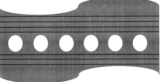
Figure 7 - Sample Shape Similar to Cross-Section of Widget Major Assembly Widget Subassem bly P arts ... 79
Chapter
1
-
Introduction
For the past 40 years the Widget industry has operated as a duopoly, with the only players being Company A and Company B. Over that time Company B has eaten away at Company A's business, leaving the industry in a current 50/50 market share. As both companies fight to stay competitive in a market where Widgets are trying anything to increase their small margins, they are looking internally at ways to cut costs and improve their internal operations. Additionally, there has recently been a sharp increase in widget demand, leading to a large backlog of orders at both widget manufacturers. For context, the widget being discussed can be considered to be a large,
complex mechanical assembly made up of many sub-assemblies.
In order to build widgets faster while lowering costs and increasing quality, the entire Widget industry has moved towards automating processes that have historically been done manually. Other industries have adopted automated processes over time, including the automotive, consumer goods, and pharmaceutical industries. Although each of these industries has its own challenges, the combination of size, safety standards, regulations, and tolerance requirements associated with widgets makes it an especially difficult industry in which to apply automation. The high cost of the equipment of the appropriate size capable of performing various manufacturing and assembly processes also presents a unique barrier for introducing automation. Therefore, it is important for Widget companies to carefully transition from manual to automated processes within their production systems.
In the first two weeks of the assignment reported in this thesis the author conducted over 20 interviews to get an understanding of the issues facing the implementation of automation. Through these interviews, trends and issues arose that would form the motivation for this thesis topic. The
focus of the study centered on automation based on the objectives of the group the author was working within.
Company A has had mixed results in effectively implementing automation technologies in the operations of its various manufacturing and assembly locations. Although successful technologies have worked as predicted, many projects have failed to meet the requirements necessary for completely automating a process, as was intended. This thesis explores one of the main drivers for why automation projects have failed to meet all of their requirements, the design of the widget itself.
1.1 Problem Statement
A transition from manual to automated processes causes technical, organizational, and
cultural challenges to be addressed in a company that has experienced difficulty in implementation when certain historically manual process are automated.
One of the technical challenges that has limited Company A from being able to effectively implement automation into their production system is the fundamental architecture of the widget. Some widget models were developed in the early 1990s, but are still designed in similar ways to widgets from the 1940s and 1950s. This, and other widgets have design architectures that were developed with manual processes in mind, where mechanics could make adjustments and on-the-spot decisions based on a variety of input materials and sizes, as well as inconsistent processes on the floor. Trying to replace a human with a robot or other automation in this environment without taking the necessary measures leads to issues at the time of implementation
The way the engineering process occurs and how the company is organized also presents challenges. There is a large body of data internally about the dynamics, energy consumption,
material life, etc. that gives design engineers and stress analysts within the company a large amount of information to draw upon when making design decisions. Production engineers who suggest changes that would facilitate the manufacturing and assembly of a widget have to overcome the large amount of historical performance and safety data based on existing widget designs. Any changes to these existing designs requires extensive stress and material analysis to be done, which takes time and a significant amount of investment. Therefore, many times design decisions are biased towards using existing designs versus changing the design to accommodate the requirements of the manufacturing engineers.
Other factors considered were the consistency of materials being received from suppliers, the documentation and understanding of the current manual processes, and the organizational challenges of sharing best practices across such a large company as Company A.
At the root of all of these challenges were two main problems. First, architects and design engineers did not have the tools to design parts and assemblies that effectively incorporate automation or production-specific requirements at the early stages of development. Second, the engineering process did not facilitate the necessary interactions and collaborations between the various engineering disciplines that develop a widget from a concept to a manufacturable product.
1.2 Purpose of Study
The purpose of this study is to address the issues with the way automation is implemented at Company A by presenting a set of solutions that address the root causes of the challenges. The thesis also attempts to provide context on the companies, industries, technologies, and behaviors that need to be understood in order to solve the issues found.
As global pressures from shareholders, competitors, and customers increase throughout many industries and regions, the push for companies to be more operationally efficient has never been greater. As processes become more efficient, there comes a point where new technologies can be of more use than the ones currently implemented in the operations. At this point in time one of the best technological solutions to this efficiency problem is automation. With their tireless motors and consistent operation, machines are able to perform tasks in ways a human never could. At the same time, humans are able to quickly solve complex problems on the spot and adjust to variations in the inputs to processes. There is therefore a need to understand how and why to properly implement automation into a production system.
In going about the transition from manual to automated operations it is important for Company A to take into account all of the ways the business could be affected by an increase in automated processes. Additionally, it is important for Company A to have robust account and financial systems in place to properly calculate and make a business case for the automation to be put in place. This study wishes to understand and show the connections between various groups within Company A in order to holistically address the many challenges facing the company at this time.
The main contribution of this study will be the finding that altering the design of the widget is the most critical part of ensuring that new technologies, such as automation, are properly leveraged and implemented in the production system.
1.3 Thesis Approach and Overview
This study will present a number of aspects associated with how to understand and change the issue of replacing manual processes with automated ones. The core argument this thesis will present is that, if companies plan on applying automated manufacturing to new and existing
products, they must take important steps to design their products with the limitations, advantages, technical abilities of automation in mind. This way of aligning the design of a product with its
subsequent automated processes is referred to in this study as Design for Automation (DfA). Additionally, this thesis seeks to show that companies must examine every aspect of their business to ensure that the automation being implemented aligns with the company's production system
strategy, competitive strategy, and internal organizational processes.
By first understanding the internal structure, as well as the engineering process flow and
production system at Company A, the study seeks to give company-specific context to the issue. The study will present the findings gained from interviews and a literature review of internal documents.
Next, the study will present the internal and external landscape of manufacturing automation. This includes commonly used automation technologies, use cases, and implementation strategies being used in many different industries at this time. By providing the reader with a robust background on existing technologies, the reader will be able to compare Company A's way of implementing automation with other companies. The thesis will then present new manufacturing automation technologies on the horizon that may affect future process improvement decisions at Company A.
The enablers to automation will then be presented to show that putting a machine in place of a human mechanic on the line requires more than just the latest automation technologies. This part of the study seeks to outline the work Company A needs to consider and do internally in order to ensure implementation of the automation is successful long before the automated systems enter the factory for installation.
This will conclude the literature review and internal analysis portion, and the study will then present ways in which implementing DfA methodologies within the engineering and organizational systems could positively impact the products, the production system, and the company as a whole. At this point, the study will first describe the Design for Manufacturing and Assembly (DFMA) principles and methodologies developed by Boothroyd & Dewhurst, the basis for the DfA principles. Then, the study will describe the way the team of technical experts were chosen from around Company A, and how this team went about developing the set of principles that could be applied to all the parts and assemblies across all widget programs. Once the principles are presented, the supporting documentation and follow-on steps will be described.
Next, the thesis will synthesize the information gained in previous chapters to develop a cohesive strategy designed to effectively implement DfA principles and best practices within Company A engineering processes, business processes, and organizational structure. In order to ensure proper implementation, this section seeks to provide guidance on how to provide design and manufacturing engineers with tools that will enable them to incorporate automation requirements into the widget design.
To show the benefits of applying DfA principles to Company A products, a case study will be presented outlining the time and cost savings that could have been gained from changing the design in order to accommodate for a new automated manufacturing process.
Finally, a conclusion of the thesis will be presented. This will include a summary of the major findings of the thesis, as well as recommendations for continuing DfA efforts within Company A. A final discussion on automation and emerging technology will also be included. This section is
intelligence, machine learning, and the internet of things could affect the future of manufacturing automation.
Chapter
2 -
Company and Industry Background
2.1 Company A
Company A is a widget manufacturer. Company A is split into its various widget programs, which correspond to each of the widget models. Each program has their own leadership and development programs. Since each widget was designed and developed at different points in time over the last 40 years, each widget program has its own way of organizing their production system.
Changes in demand and internal culture have also shaped the way the production is organized within each widget program. This can be clearly seen by the production rates of each program. For example, the production rate of its small widget is up to four times more widgets per month than its newest large widget program. The amount of time it takes each widget to be made depends on the market demand, production capabilities at Company A and its suppliers, size of widget, number of parts, and a host of other factors.
2.2 The Widget Industry
Widgets play an important role in the world economy. Widgets have increasingly faced pressure on their already small margins, forcing them to ask more from the widget manufacturers. Widgets now are not only expected to be reliable, they must also be energy-efficient, easy to operate, and have low maintenance costs throughout the product's usable life. The sheer size of a widget and the complexity of the interdependence between the different systems and sub-assemblies makes it an operational challenge to have all of the relevant engineers communicate with each other and share critical information in the development process. All of these constraints,
combined with the highly stringent safety regulations and standards imposed on widgets, makes the design and building of a widget an especially difficult and complex process.
The Widget industry is dominated by a small number of players, and has become more consolidated over time through a series of mergers and acquisitions.
The high barriers to entry prevent smaller companies and countries from entering the market without significant investment and effort. Equipment, material, and development costs are the main deterrents to new entrants, but engineering and manufacturing know-how also play an important role in keeping a company or state entity from developing a widget from the ground up. New widgets will have to compete with tried and true widget models that have a safety record measured in decades, and in a market that is rightfully wary of risk and new entrants.
Company A and Company B have been in fierce competition since Company B was founded. The late entry manufacturer has slowly been taking market share away from Company A's dominance in the market.
The competitive strategy of developing widgets is based on the widget's use case, based on the way the primary customers want to serve various markets. Both companies strategically place themselves on different places on the energy efficiency curve in order to capture a certain segment of the market. New sub-component designs, materials, and manufacturing processes allow the companies to reach untapped areas on the energy efficiency curve. Therefore, improvements in the internal operations of both companies have a direct impact on how competitive the company can be with its product offerings.
2.3 Widget Design Constraints
2.3.1 Widget Weight
The most important constraint to the design of a widget is its weight. Weight is a critical factor that can be controlled by the manufacturer, and it is a metric that is highly scrutinized by primary customers in the Widget industry when making purchasing or leasing decisions. The weight of the widget is directly related to its energy efficiency, which has an impact on the operating life cost of the product. In the Widget industry, the weight of a widget is sometimes seen as the most important measure of success or failure of a program. The push to lower the weight and increase energy efficiency is one of the biggest reasons widget manufacturers are using lighter and stronger materials in new models.
The cost of a widget is directly linked to the energy efficiency of the widget. Since weight is one of the main drivers of energy efficiency, the weight of a widget has historically been the most strategically important metric for designing widgets at Company A. As such, the engineering teams have been trained to make weight the objective function when optimizing the design of the widget. Over the years, Company A's engineers have built models that can accurately estimate the weight impact of certain design changes. Weight will be a common theme throughout this study and will form the basis for many of the tradeoffs that need to be made to make widgets more producible, whether with automation or not.
2.3.2 Regulations
The strict regulatory standards surrounding widget design and operation are an important factor to understanding the constraints widget manufacturers face. Designs need to be approved by the safety regulator in the US and by other international regulatory bodies to allow the Widgets
to operate within certain countries. Additionally, the operations of the manufacturing centers need to be reviewed and approved in order to ensure that the intended design is being built in a manner that takes the proper safety standards into account. If a design change is significant enough in itself, or if it causes a significant change in the manufacturing process of the part or sub-assembly, the company needs to report the change to the proper authorities. This means that widget manufacturers must take the potential regulatory approval process into account when making design decisions that significantly deviate from the approved design.
2.3.3 Supply Chain
Although a lot of the fabrication and assembly work needed to create a widget is done by the widget manufacturers themselves, there is a significant amount of work done by suppliers. These global suppliers form the basis for the complex Widget supply chain, and have different capabilities based on their expertise with certain materials and processes. These capabilities are important because in some cases parts that are dozens of feet long need to have tight tolerances. This is something unique to the Widget industry because of the reasons described above.
When engineers at any Widget firm want to make changes to an existing process or are developing a new widget model, they are sometimes constrained by the suppliers' tools, machines, process capabilities, and internal manufacturing know-how. Because of the high barriers to entry of Widget suppliers, it is often difficult to bring new suppliers up to the necessary level. Therefore, supplier planning is very important when making significant changes like automating a manufacturing process.
The competition between the two large widget manufacturers has forced both companies to be innovative in their production systems in order to reduce its manufacturing costs. Both
companies have also turned to automation for quality, flow efficiency, and worker safety gains. As will be discussed in the following chapters, the design methodology each company has adopted over time has had an effect on the design of their production system, and subsequently, how much it costs them to make each widget. This study will focus on the systems and processes within Company A.
Chapter 3 - Company A and the Widget Industry
It is important to understand Company A's organizational structure and engineering processes in order to get the necessary context of the challenges with implementing automation. The effect of this structure and process on the way the company manufactures their products can then be understood.
3.1 Engineering Structure and Process at Company A
3.1.1 Engineering Organization
Company A's engineering group is at the highest levels split up by function. Design engineers, production engineers, stress analysts, and all other engineering disciplines each report up through their own leadership. This was done in order for managers and directors to be able to accurately assess an engineer's performance and make decisions on an engineer's career path and advancement.
The disciplines are then split up by the section of the widget they have been assigned to
-Major Assembly A, -Major Assembly B, -Major Assembly C, etc. This creates specialists from each discipline in the various parts of the widget, but this structure also allows engineers of a certain discipline to move around and work on other sections of the widget if it fits their interest. When Company A needs to concentrate their resources to accelerate the pace of development, they can draw engineers of all disciplines to one project. In contrast, if engineers were at the highest levels assigned to a section of the widget or to a specific model widget, this flexibility would not exist.
Development of a widget is directed by the managers and directors of each widget section, with one integration team focused on ensuring the requirements of the separate sections and
systems are aligned. Project managers build schedules and allocate resources based on the stage of development. These two groups work together to track the progress of the project and ensure that everything is running on schedule. However, as will be discussed in the next section, this structure also presents some challenges when collaboration between engineering disciplines is necessary.
The development of a widget design is one most complex efforts in the world. Engineers of all disciplines in many different locations must coordinate efforts for years to gradually define the design of the widget. With hundreds of thousands of parts and even more interdependencies between them, it is a daunting task to work out all of the details of the widget while ensuring that all of the requirements at every step of the process are met. This complexity also begets a
significant amount of risk.
In the development of its new widget, Company A used new materials extensively. This allowed engineers to develop new designs to accommodate differences in material properties and manufacturing processes. These designs moved away from traditional widget designs and allowed Company A to be innovative in their manufacturing and assembly processes. But delays in the development due to analysis and testing setbacks are a testament to the difficulty of developing new widget designs from scratch.
To mitigate the risks of designing such a complex product, the reuse of old designs used in previous widget models is prevalent in the engineering process. Since Company A has decades of stress and material data on certain Widget Major Assembly design geometries, design engineers reuse those geometries because they know it works and it is safe. The author found that it was sometimes difficult to change the design to accommodate manufacturing requirements because of the amount of analysis that needs to be done in order to validate the safety of the new design.
The power structure between the engineering disciplines at Company A is important to note. Design engineers have historically had a large amount of power within the organization. Through discussions with design and production engineers, the author found that production engineers many times had trouble convincing design engineers to make certain changes that would improve the fabrication or assembly process. One of the arguments design engineers would use was because
the changes would lead to weight increases.
One of the main issues production engineers faced was Company A's inability to accurately understand how to trade-off between widget weight and production efficiency. The production engineers could create estimates on how much would be saved over time in the fabrication or assembly with a certain design change; and the design engineers could estimate how much the change would cost in terms of analysis and validation costs and weight increases. But because there were no guidelines or policies as to how to compare and trade off these two analyses, the more powerful design engineering group would be more successful in negotiations.
This dynamic between the engineering groups leads to Company A designing widgets that are very light, but hard to manufacture. And therein lies many of the underlying issues that the thesis is attempting to investigate. Because weight minimization has been the objective function for the optimization of the widget design for so long, it has led to a sub-optimized production system. In the past, it was acceptable to have this imbalance in decision making because humans could work around design issues. With automation, the company can no longer ignore the importance of understanding the trade-offs between widget weight and production efficiency.
3.1.2 Engineering Process
Company A uses a gated process for its widget development, with each stage increasing the definition of the design from general concept to production readiness. After each stage of development there is a review gate that ensures all of the requirements for that stage have been met. The review is done by Company A's engineering leadership over a number of days. Within each stage the deliverables from each engineering discipline are reviewed and approved before being marked as complete by the project manager.
In each stage there is a large concentration of one engineering discipline. Their main task is to meet the high-level requirements imposed by the market and the company leadership. On the other hand, deeper in the development stages, design engineers must take what the architects put together and attempt to fill in the details. Additionally, when the production readiness stage comes, production engineers take what the design engineers have detailed and are tasked with making the design producible.
Although it depends on the program leadership, through interviews and research the author concluded that there was not a significant amount of work transition from one engineering discipline to another between the various stages of development. Tasks were broken up into discrete stages that did not incorporate many of the requirements of the downstream development steps. That is, instead of engaging the stakeholders in the next step of the development process, each engineering discipline worked independently based on the design they received from the previous process steps. For example, only after the design engineers and stress analysts completed the detailed design of the widget were the manufacturing engineers engaged to begin the process of manufacturing planning and strategy.
This "hand-off' procedure created inefficiencies in the process because not all of the necessary downstream engineering requirements were taken into account. If a production engineer had an issue with a part or assembly, they would have to go back and change the design potentially months after the design engineer worked on it. This not only causes time inefficiencies in the process, it also increases the cost due to more engineering development time. Additionally, this "hand-off' process creates cultural rift between the engineering disciplines, further deteriorating the ability to collaborate at various stages of development.
The author also observed that certain development groups did not encourage design engineers to go out on the manufacturing floor and understand how their part would be installed. This caused issues when the production engineers would try to create a process for an assembly and realized that one part or sub-assembly wouldn't be able to be lifted by a mechanic or did not have the clearance to reach its place in the assembly. Digital models can be used as a way to work on the design of a widget, but there are certain benefits to understanding how the parts in the digital model are realistically installed, fabricated, and assembled. At the time of the study, the use of human simulations at the development stage was not prevalent. However, these simulation platforms are commercially available and are used in industries such as automotive and defense.
An important point to understand when thinking about the Widget industry and the pressure on the engineering process is the way widgets get announced and financed. Once a widget model is announced by a widget manufacturer, the company starts selling the product and makes commitments on when it will deliver the product to its primary customers. Additionally, in order to purchase the widgets, the primary customers or leasing companies need to make a case to a bank or lender to borrow the money necessary to buy the widget [5]. In these discussions, primary customers must make commitments and projections to the banks on when they will begin turning
a profit with the new widget. Banks expect to be paid back, so they track the delivery of the widgets to the primary customers carefully. If there is a delay in the delivery, banks may impose charges or higher interest fees on the primary customers per the accepted contract. Therefore, when a widget is announced and launched there is a large amount of pressure on the widget manufacturers to meet deadlines that are sometimes almost a decade into the future. All of this pressure manifests on the engineers that need to complete the design of a widget in as little time as possible.
3.2 Traditional Manufacturing at Company A
Company A has three main locations where it assembles all of its widget models. Because each model widget was designed in a different time period with certain materials, process capabilities, and manufacturing technologies available, each program has a unique way of manufacturing its widgets. Therefore, the production system of each widget model differs from the others. This creates unique challenges when upgrading the manufacturing processes because the new technologies are sometimes not able to be replicated in other widget models.
The older models were designed with manual assembly in mind, and therefore a large amount of the work of putting the fuselage and Widget Major Assemblies together is done by hand. Because of the complex nature of the widget design, mechanics doing the work need to make fit adjustments based on variations in the sub-assemblies or parts. Whether it be assembling the fuselage or putting interiors in, putting a widget together in many ways is still a craft. Best practices on how to fit certain parts together are passed from one mechanic to another, and in some instances only a select number of mechanics have the expertise to assemble critical parts of the widget. Although it may seem that an hand-crafted approach is one that could allow for certain parts to be installed incorrectly, the hand fitting of parts and sub-assemblies creates a tight, custom fit for all assemblies.
For most of its history, Company A has produced aluminum widgets, but has recently moved to using new materials for its newer models. The manner in which major parts are assembled is common across all materials; in both Company A and Company B widgets the use of fasteners is prevalent. Although material and process technologies have progressed greatly over time, the way fasteners are fastened has stayed the same for almost 90 years. One mechanic stands on the outside of the widget and inserts a fastener, while a mechanic on the inside "bucks" the fastener. For either person in this process, the act of fastening or bucking is hard on the back, shoulder, elbow, wrist, and hand. This fastening process is one of the main drivers for developing automated technology and getting the mechanics out of this hazardous environment.
Other processes associated with making a widget include drilling, counter-sinking, sealing, painting, as well as any of the traditional manufacturing processes associated with fabrication or subtractive manufacturing.
It is important to note that it is very difficult to assemble a widget. Ensuring that the fasteners that hold the widget together withstand the stress and material life the widget will be subjected to throughout its operating life is extremely hard. In the automated assembly of most products, processes can be done serially, with each robot doing one process as the part or sub-assembly moves down the line.
But in the Widget industry there are limitations to this. Since the Widget Major Assembly must maintain pressure, any fastener that holds the Widget Major Assembly together must be put on in a very specific manner. The drilling, counter-sinking, sealing, and filling of that fastener must all be done in one operation to ensure that a tight seal is formed between the outside and inside parts. This makes it hard to design automation technologies that are specialized and do one task at a time. The need to do multiple operations on the widget in sequential order while holding
pressure between adjoining parts leads to complex end-effectors that do have to do many tasks. The shortcomings of this approach are examined in later chapters that cover the technical aspects of automation technologies.
3.3 Development of Indexing
Company A's manufacturing has changed over time based on the widget design and the available manufacturing technologies available at the time of development. It has also changed based on emergent manufacturing methodologies that Company A adopted from other industries.
Historically, Company A and most Widget manufacturers built widgets in large reference fixtures (or "tools") that accurately positioned all of the pertinent parts or sub-assemblies at each process stage. This ensured that all of the parts or sub-assemblies were referenced to absolute, global coordinates on the fixture in a repeatable way. Special fixtures were designed for each major assembly process, custom to each widget model.
Based on the success automotive companies had with the use of fixture-less assembly, Company A in the early-to-mid 1990s wanted to emulate the assembly methodology. Fixture-less assembly is key to an automated manufacturing system because it allows the parts and sub-assemblies to be assembled without the need of globally-referenced fixtures, and allows parts and assemblies to be referenced to each other. Additionally, by removing the need for fixtures, parts can be assembled in the open without the limiting structure of a fixture.
At the core of fixture-less assembly is the use of indexing and key characteristics [6]. Indexing is the act of specifying, at the design stage, the manner in which parts will be assembled relative to each other. Key characteristics are points on each part or sub-assembly that are that are critically important to the effective joining of mating parts. These key characteristics are identified
at the design stage, and are controlled throughout the fabrication of parts and through each sub-assembly step prior to final sub-assembly. This has an impact not only to Company A, but also to the suppliers that have to ensure the key characteristics are within tolerance throughout fabrication and sub-assembly.
Additionally, indexing calls out the specific manner in which parts will be assembled. By understanding the degrees of freedom each part has relative to the part it is mating to, design and production engineers can work out in what order of orientations the parts can be assembled to ensure that the parts will be put together in a repeatable manner. In doing so, the engineers can take the guess work and variability in assembly at the early stages of widget development. Dr. Daniel Whitney's book, Mechanical Assemblies, is a great resource for learning about how indexing is used across a variety of industries.
Indexing is used extensively in the automotive industry to ensure that all of the assemblies are developed and refined at the design stage. During automotive assembly, all of the variations in assembly orientations have been worked out long before a mechanic touches the part. This removes the ambiguity of putting parts and sub-assemblies together, allowing the mechanic to do the given assembly task quickly and in a repeatable manner. The way indexing defines assemblies is a key enabler to automated assembly, where all of the ambiguity and decisions a machine needs to make are accounted for in the product development process.
3.4 Automation Design and Implementation at Company A
The Widget industry has been slow to adopt automated manufacturing due to the high cost, tolerance constraints, and safety concerns. But as automated technology has become cheaper, more accurate, and generally more understood, manufacturers have been replacing their repetitive and dangerous processes with automated technologies. Over the past 30 years, Company A has worked
with a number of automation suppliers and integrators to develop customized automated systems. Company A's focus has historically been on the engineering and manufacturing of widgets, so it has looked outside of the firm to develop automation solutions to its manufacturing challenges. The large automation integrators have been major automation suppliers and integrators to both Company A and Company B.
Normally, a widget manufacturer will have a need for automation in a certain part of the production system and will create a set of requirements for that automated system based on production needs, internal production process compatibility, cost, and other factors. Automation suppliers and integrators then submit proposals for what they believe is a solution that meets the requirements. After some feedback and refinement of the proposals, an internal analysis is done to compare the final designs. After a series of decisions and approvals, one technology is chosen for development. Engineers at Company A and the automation integrators then work together to develop the idea and further work out the details of the process, technology, and implementation schedule. After the automation technology and design is decided upon, it is implemented in the manufacturing environment. This is followed by a large amount of validation and verification of the automated process to ensure quality requirements are met. After this stage, the process differs for each product, process, and automation technology proposed.
The weight and size of the parts that are fabricated and assembled also plays a role in the uniqueness of the product and the industry, and its ability to transition to a more automated production system. Just moving parts within a process or from one process to another requires significantly more energy than in any other industry that is automating its processes. Looking at the power to move parts, from a dimensional standpoint, it can be examined as [7]:
M x L
Power = 3
Where M is the mass of the object, L is the length the object needs to travel, and T is the time it takes to move that part. In theory, the more heavy the part or sub-assembly is, the more power is required to move the object in the same amount of time or across the same length. In auto manufacturing, where the parts are close to human scale, this amount of power output requires reasonably sized automation. But in the case of the Widget, the automation technology required is much larger, more expensive, and significantly heavier.
Due to the aforementioned constraints on the design of the widget and the hand-crafted nature of the current manufacturing processes, the automation implemented at Company A to this point has in some ways had to adjust to the existing design of the part or sub-assembly. As will be discussed in later chapters, this causes inefficiencies in implementation because the automation must be made more complex and costly to adjust to the plethora of potential configurations of input materials, as well as the potential variability in the existing manual process.
Although Company A has been working with automated systems for over 30 years, the way automation technology has changed over the years has forced the company to work with different automation suppliers that have leveraged the existing technologies at the time. Right now, Company A works with companies that have been mostly successful in the automotive industry. These automation suppliers have been able to use flexible automation (as will be discussed in the following chapter) to allow automation to do more complex human operations. Both Company A and the automation suppliers are constantly exploring new ways of tackling the issues of automation manufacturing processes in the Widget industry. Therefore, Company A is in a
learning phase with these companies, and it will take time to improve on their relationship and the quality of the delivered automation solution.
Company A's relationship with its automation suppliers is complicated by the fact that there are no standard guidelines for how the automation should be designed. This, along with the fact that every widget program works in a silo, leads to every widget program developing relationships with the automation suppliers independently. The lack of centralization leads to every automation project being an exercise of reinventing the wheel for a specific application.
Chapter 4 - Manufacturing Automation
Merriam-Webster defines automation as:" the technique of making an apparatus, a process, or a system operate automatically
" the state of being operated automatically
" automatically controlled operation of an apparatus, process, or system by mechanical or
electronic devices that take the place of human labor
In this sense the definition of automation is rather broad; even a TV remote control can be defined as automation. But for the purposes of this thesis the focus will be on the automation of a process. Specifically, we will focus on automating fabrication and assembly processes within the manufacturing environment. In this context, automation can be thought of as a unique arrangement of motors, actuators, sensors, and controls, combined with specialized end-effectors that are built to complete one or more processes.
4.1 Automation
Automation is just one of many tools that manufacturers can use to improve the efficiency of their operations. Where exactly to place the automation and at what point in time it is appropriate to introduce the automation depends on the specific production strategies and demands of the company being studied. As Figure 1 and Figure 2 [8] show, the right level of process-driven manufacturing depends on the expected productivity and volume from the production system.
Coi a v~ntr roruufac~ui n
M4 f t ,e lran u fa r m n ctu n n g
Soil automation --- Hard auV ation Increasing productiv. y
-Figure 1 Recommended Flexibility in Production Based on Productivity and Volume Output
Tvp> I A, prohcli N m111be1*r 1)r4ilI d I y I i I prdutIi.
Exp 1er imIeInl l r 1) 'A rt-typ 1 All tlypeAs,
Ie r hma1 I badch 5I ) Aircraft, i-hine dies
hath i*r high qmud ity H M0-I 1 I H I Tuck ar'culturral iii hine~ry. jet engiines. dieseI
lngine>, orh pcdic 1e dvice
And* beveraI'gc' ('0tainers
Figure 2 General Manufacturing Guidelines for Relative Volumes
For Company A some processes fall within the "job shop" category, while some processes fall within the "conventional flow-line" category. For example, final assembly of the widget involves putting together large pieces of the widget. These interfaces between these large pieces are the culmination of a large set of tolerance stack-ups created from the individual parts and sub-assemblies of the large pieces. It takes a significant amount of effort and human touch to put these together because of the stack of imperfections that manifest themselves at the ends of the major parts. In this sense, that assembly process is much like a job shop process. But when examining the internal systems that go into the widget - for air, electrical, water, etc. - there are thousands of feet of systems in each widget. Since the volume of systems that go into each widget is so large,
many of the processes to make these parts are standardized. In this sense, the manufacturing processes for high-volume, low-variety parts are more like a conventional flow-line. In most cases,
the manufacturing of this type is more easily automatable. Understanding the standardization level, expected volume, and quality requirements of each process is important when deciding whether automation is a right fit for a particular process.
Through time different types of automation have emerged that bridge the gap between the various production volumes and mixes.
4.1.1 Hard Automation
Hard automation machines are designed for very specific tasks with high volumes with low variability of the input material or the process. Hard automation can be seen in places where one operation will produce thousands or tens of thousands of units in a relatively short amount of time. By having one dedicated machine to do one specific process, manufacturers can instantly increase
the throughput in that specific area of the production. This automation is also relatively cheaper compared to the other types of automation. An example of this type of automation is a metal stamping press in a high-volume production line. This single-purpose machine uses one die at a time, and has the ability to form the metal sheets into the desired shape very quickly.
The downside to hard automation is that if the product design changes or if the process needs to be improved, modifying the automation is difficult and potentially prohibitively expensive. This means that for product categories where there is fast obsolescence, hard automation becomes too large of a fixed cost and may take longer than the lifecycle of the product to get a return on investment.
In a high-volume production environment a stamping press is used to make the same metal shape, with different stamping machines within the production system dedicated to the forming of
individual part types. In a lower-volume production system, stamping machines that are able to quickly change dies can be used.
4.1.2 Soft Automation
Soft automation is a more flexible form of hard automation. This type of automation allows for different interfaces to be switched on and off, allowing for multiple processes to be done on a single machine. This kind of automation can do multiple jobs on a single product before it moves to another process, or it can allow for different product configurations to allow customer customization. An example of soft automation is a computer numerical controlled (CNC) machine. This machine can perform many subtractive manufacturing operations within one system, giving it the flexibility to create different parts with the same machine.
With the increased flexibility comes a decrease in the speed of the automation. By having to switch tools and make adjustments to accommodate different processes, soft automation is not as efficient as hard automation. For example, in a high-volume production environment, making a hole in a part may be the task of a single drill press that only moves up and down. In a lower-production scenario, a CNC may be used to create different sized holes based on product types or production needs.
4.1.3 Flexible Automation
Flexible automation is the ultimate type of programmable automation. An example of this type of automation is the six-axis robot seen in a variety of manufacturing environment - from automobiles to toys. The multiple degrees of freedom of this automation allows it to be completely programmable in its function and motion. The way the software is written to create the paths for these robots is more important here than with hard or soft automation, where the mechanical
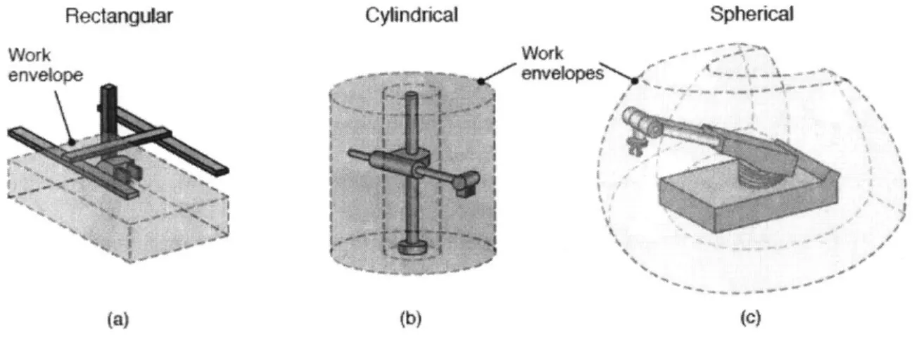
architecture defines the abilities of the automation much more. These robots can do any number of movements and, depending on the specific design, have a large range of motion. Figure 3 shows the typical work envelopes (the available volume of operation of the automation) for a few types of flexible automation. Figure 3 [8] shows the range of motion and work envelopes for a few types of flexible automation.
Rectangular Cylindrical Spherical
Work W0rk
envelope ' enVelopes
(a)(c)
Figure 3 Types of Flexible Automation and Their Work Envelopes
Flexible automation also allows you to reuse the robots for different operations over time. If a process becomes obsolete due to a change in the product, flexible automation can be reprogrammed to do another operation in a different part of the manufacturing process. This level of flexibility makes this type of automation a good choice for companies that are looking to automate processes in a fast-changing market.
But the flexibility comes at a loss of speed and efficiency compared to the other types of automation. Since the configuration of the motors, actuators, and end-effectors is done in a standard way, the automation has to adjust to the process and not the other way around like in soft and hard automation. Additionally, the amount of force six-axis robots can impart on an object is limited by the inherent design of the robot. The DC motors inside this automation allow it to be completely flexible, but the maximum torque they can create is limited by the size of the robot.
Just like in many real-world cases, the larger and heavier the work piece to be handled by the flexible automation, the larger the robot will be.
Lastly, the amount of programming and infrastructure necessary to ensure these robots run efficiently is substantial. With increased levels of process complexity comes more coding to take into account the various use cases and part variations. Additionally, flexible automation requires fixtures to hold the work pieces, support structures to ensure that the motion of the automation does not re-reference its position relative to the work piece, and sensors and controls to create feedback loops. After everything is installed, the automation needs to be validated to ensure consistent, quality output. The cost of all of these additional components and activities needs to be taken into account when company purchases automation in order to properly calculate return on
investment timelines
4.1.4 Governing Equations of Flexible Automation Motion
Since flexible automation has many degrees of freedom, even simple translation can be a challenge to program. Luckily, there has been significant advancement in the mathematics of robotic motion that allow the motor control commands to be made more simply. To show the basic concept of the mathematics, a simple example will be shown [9].
In a two-degree-of-freedom system, there are two links and two joints, with a point at the end that will be used as the reference for what we want the robotic arm to do. Figure 4 shows a visual representation of this sample system.
y
2 End Effecter
00
iLink 0
Figure 4 Example of Two-Degree-of-Freedom Robotic Arm
Based on the 0 and 1 angles and lengths, respectively, we can simplify the absolute (x,y) position of the end-effector (in this case a claw).
Xe(01, 02 =' CO c01 f2 cos(01 02
y, 1 Josin t ,sin(01 +0)
Furthermore, using a Jacobian Matrix of differential movement, we can understand what small movements at the end-effector will have on the change in motion over time (or velocity) of the 01 and 02 angles, and then translate the absolute reference frame to the reference frame of the end-effector. This is shown below where the changes in movement of x and y are correlated to changes in movement of
Oi
and 02.r e x(0 T 0) aXe (Ri, 02)
&Y(OiO ) aye(9i, 2)
The previous values for the absolute positions of x and y can be input into the Jacobian Matrix, and gives us:
- f, sin0, - t2 sin(0, +02) - f 2sin(O, + 0)
t ICos 0, + t COS(01+ 02) C 2 COS(01+02) )
This allows the translation of the desired motion at the end of the flexible motion of the robot to commands for the individual motors in the system. Although adding degrees of freedom to the robot model will make the equations more complex, the concept of translating desired motion from the end of the robot to commands to specific motors in the system is the same.
4.1.5 End-Effectors
End-effectors are the attachments that go on the end of soft and flexible automation that actually perform the intended processes. Whether it be sanding, painting, drilling, or any other process, end-effectors act as the link between the motion of the flexible automation and the needs of the process. Depending on how it is defined, hard automation also has an "end-effector", but this usually is manifested as a die, drill chuck, or a simple mechanism that interacts with the work piece.
Sensors can also be placed between the end of the automation and the end-effector. These sensors can monitor force, torque, and/or moment acting on the effector to ensure that the end-effector itself and/or the work piece is not subjected to too high of stresses. There are a number of additional sensors types that attach to - or are incorporated within - the end-effector that provide feedback to the automated system.
The complexity of the end-effector depends on the requirements. The more operations and monitoring that needs to be done on the work piece at one time, the larger and more complicated the end-effector will be. Manufacturers need to carefully decide what processes will be done by certain robots because, if the process is too complex and requires many operations, the size of the
end-effector becomes prohibitive to the process because of limitations in accessibility. Additionally, the increased weight of the end-effector due to the increased complexity of the required operations causes the robot arm to move more slowly. If a larger robot is needed to account for the increased weight, it could exacerbate the accessibility problem.
At Company A, different end-effectors were designed from the ground up for every new application.
4.2 Emergent Technologies
Technological advancements in motor design, control theory, and manufacturing precision have changed the way automation is applied in a variety of industries. Tolerances that would be prohibitively expensive to meet 20 years ago are now financially accessible for small and medium sized businesses. Algorithms that tell robots how to move are easily found on the internet and can be customized in quick time. This accessibility to "high-tech" tools has led to significant strides in the types of automation available to manufacturers that are outside of the hard, soft, and flexible automation previously described. As manufacturing and software technologies evolve, the definition of what automation in the manufacturing environment means will change as well. The interactions between man and machine will begin to mesh and transform the way products are designed and built.
4.2.1 Collaborative Robots
A big issue with current automation is the lack of feedback sensors that let the robots know
when a human is nearby. Because automation is built with the forces necessary for production in mind, they are able to impart forces that are dangerous to humans. Errors or imperfections in the way the programming is written for these robots can lead to unpredictable behavior of the