Design of Assemblies with Compliant Parts: Application to
Datum Flow Chain
by
Gennadiy Goldenshteyn
B. S., Mechanical Engineering University of California at Berkeley, 2000
Submitted to the Department of Mechanical Engineering In Partial Fulfillment of the Requirements for the Degree of
Master of Science in Mechanical Engineering
at the
MASSACHUSETTS INSTITUTE OF TECHNOLOGY
June 2002
D 2002 Massachusetts Institute of Technology All rights reserved
BARKER
MASSACHUSETTS INSTITUTE OF TECHNOLOGYOCT 2 5 2002
LIBRARIES
Signature of AuthorDepartkknt of Mechanical Engineering May 24, 2002
Certified by
aniel E. Whitney Senior Research Scientist Center for Technology, Policy and Industrial Development Lecturer, Department of Mechanical Engineering Thesis Supervisor
Accepted by
Prof. Ain A. Sonin Chairman, Departmental Committee on Graduate Students
Design of Assemblies with Compliant Parts: Application to Datum Flow Chain by
Gennadiy Goldenshteyn
Submitted to the Department of Mechanical Engineering In Partial Fulfillment of the Requirements for the Degree of
Master of Science in Mechanical Engineering
ABSTRACT
Datum Flow Chain (DFC) is a methodology that provides tools and vocabulary to support design of assemblies. The goal of DFC is to design assemblies that satisfactorily deliver important customer requirement, or KCs. DFC is not able to deal with compliant parts due to inability to determine locational responsibility transfer relationships through a compliant part. Up to now, compliance of parts was ignored in DFC methodology, and compliant parts were assumed to be rigid.
In industry, compliant parts play a significant role in delivering KCs in an assembly. Concepts of flexible and rigid directions of a compliant part are introduced. Two distinct ways of assembling parts, in series and in parallel, are presented. Parallel assembly results in a subassembly that is stiffer that either of its components, while serial assembly does not. Sequence of parallel and serial assembly steps can influence the rigidifying rate of the assembly. Rigidizing step for a compliant part is defined as the first parallel
assembly step for the part that results in a rigid subassembly. During the rigidizing step
DFC links through the part are established.
KC conflict is a serious challenge to successful assembly design. KC conflict occurs when there are not enough degrees of freedom in an assembly to independently deliver all
KCs and is undesirable: delivery of one KC can place delivery of another KC in jeopardy. Method for detection of KC conflict in an assembly using screw theory is presented.
Overconstraint of compliant parts, if possible, is an effective way to resolve KC conflict. Concept of Effective Locating Zone (ELZ) is developed as a tool for determination of locational responsibility transfer relationships through a compliant part. It represents a region of a compliant part where an incoming locator carries all location responsibilities. ELZs are established during the rigidizing step in part's assembly. Two methods for establishment of ELZs are presented: precise determination via a membrane-based model
of the part if detailed part information is available and approximation via a beam-based model of the part if detailed part information is not available. Method to properly establish DFC links through a compliant part using ELZs is presented. Finally, all topics
of this thesis are united to form a comprehensive DFC-based system for top-down design of assemblies with compliant parts.
Thesis Supervisor: Daniel E. Whitney Title: Senior Research Scientist
ACKNOWLEDGEMENTS:
I would like to thank my advisor Dr. Daniel Whitney for his guidance, support, and
patience. He had a profound influence on my life during the last two years, and I have learned much from him, both as a scientist and as a person. I have greatly enjoyed working with him.
I feel greatly indebted to my family. Without a question, none of my accomplishments
would be possible without their love, support, and encouragement. No words can truly describe my gratitude to them.
I would like to thank Mary Ann Wright, Craig Moccio, Mike Trygar, Marsha Ryan, and
Art Hyde at Ford Motor Company for providing me with valuable industry experience and support. I would like to thank Dr. Chris Magee for helping me find the right audience within Ford. I would also like to thank the Ford-MIT Research Alliance for supporting this work.
It is impossible not to mention great friends I have made at MIT. It is because of them that I will remember this place with great fondness. I thank Alberto, Fredrik, Gaurav, Peng, and Jagmeet for their friendship. Without their ability to both hold a stimulating scientific discussion and come up with a timely joke, these past two years would not have been so enjoyable.
TABLE OF CONTENTS
Abstract 3 Acknowledgements 4 Table of Contents 5 List of Figures 7 1. Introduction 9 1.1 Motivation 9 1.2 Goals 10 1.3 Prior research. 111.4 Structure of the Thesis 14
2. Datum Flow Chain 17
2.1 Datum Flow Chain method of modeling assemblies 17
2.2 Key Characteristics 20
2.3 Part features: mates and contacts 22
2.4 Constraint states in the assembly 24
2.5 Mathematical methods used with DFC 25
2.5.1 4x4 Matrix transforms 25
2.5.2 Screw theory 26
2.6 Advantages of top-down design using DFC methodology 27
2.7 DFC and flexible parts 28
2.8 Chapter summary 29
3. Compliant parts in assembly 31
3.1 Use in the industry 31
3.2 Compliance of a part 32
3.2.1 Directions of a compliant part: flexible vs. rigid 32
3.2.2 Types of compliance 34
3.3 Assembly as a removal of degrees of freedom 36
3.4 Different types of assembly of compliant parts: serial vs. parallel 39
3.5 Rigidizing assembly step 41
3.5.1 Choosing optimal rigidizing step 44
3.6 Springback 45
3.7 Chapter summary 47
4. KC conflict in assembly 49
4.1 Definition of KC conflict 49
4.2 Causes of KC conflict 50
4.3 "Single part" KC conflict 52
4.3.1 Use of Screw Theory for detection of "single part" KC conflict 53
4.4 Resolving KC conflict 55
4.4.1 Resolving "single part" KC conflict through overconstraint of compliant parts 56
4.5 Chapter summary 57
5. Effective Locating Zone 59
5.1 Defining ELZ 59
5.2 Locational Responsibility Ratio 60
5.2.1 Relationship between ELZ and LRR 61
5.3 Establishing ELZs 62
5.3.1 Minimum acceptable LRR 63
5.3.2 Boundary conditions at locators 64
5.4 Mathematical Methods for ELZ determination 64
5.4.1 Membrane-based approach for precise ELZ determination 65
5.4.2 Approximation of ELZ via beam-based modeling 66
5.5 Linking incoming and outgoing mates through compliant part 75
5.5.1 Influences on size of an ELZ 78
5.6 Springback and ELZs 79
5.7 Chapter summary 81
6. Systematic design of assemblies with compliant parts 85
6.1 Nominal design phase 85
6.2 Constraint Analysis Phase 88
6.2.1 Determination and analysis of ELZs 90
6.4 Chapter summary 94
7. Conclusion 97
7.1 Summary of major points made in the thesis 97
7.2. Scope for future research 99
References 101
Appendix A 107
LIST OF FIGURES
Fig. 2.1 Datum Flow Chain of a typical automotive front end 18
Fig. 3.1 Structural component assembled from two compliant parts 32
Fig. 3.2 Flexible direction of a compliant part and the associated flexible plane 34
Fig. 3.3 Automobile Front End 36
Fig. 3.4 Serial vs. Parallel assembly 40
Fig. 3.5 Effect of assembly sequence on assembly rigidifying rate 42
Fig. 4.1 KC conflict due to not enough degrees of freedom present in the assembly 50
Fig. 4.2 KC conflict due to improper assembly sequence 51
Fig. 5.1 Relationship between ELZ and LRR 62
Fig. 5.2 Boundary conditions at locators 64
Fig. 5.3 ELZ determination for automotive fender 67
Fig. 5.4 Profiles of LRR loss along beams for estimation of ELZ 71
Fig. 5.5. ELZ estimation for automotive fender via beam-based modeling 73
Fig. 5.6. Using ELZ to link incoming and outgoing mates 76
Fig. 5.7. Using ELZ to avoid KC conflict 77
Fig. 5.8. Use of contacts to limit the effect of spring back 80
CHAPTER 1. INTRODUCTION.
1.1 Motivation.
Assemblies are more than a collection of individual parts put together. Rather, assemblies
are systems of parts that together perform some function. Assemblies, not individual
parts, are what constitute a final product and deliver value to the customer. Despite this,
current design in the industry is part-centric, with assembly merely an afterthought. Work
in assembly is basically limited to the way parts can be joined together with least problems (see, e.g., [Boothroyd and Dewhurst, 1991]).
Such researchers as [Lee and Thornton, 1996] and [Mantripragada et al., 1996] have
brought attention to overall assembly quality and advantages of top-down design. It has
been argued that the top-down process can reduce the design time, avoid potential
mistakes during initial conceptual design phase, and lead to better, more robust
assemblies. A methodology to support top-down design called Datum Flow Chain (DFC)
was introduced by [Mantripragada and Whitney, 1998]. It provides a method, together
with a vocabulary and a set of symbols, for documenting a location and constraint
strategy for the parts and relating that strategy explicitly to the achievement of customer
requirements. DFC allows for design of assemblies at the very early stages of product
development, and can be deployed while only limited information about individual parts
Prior to now, the work in top-down design, including DFC, focused on rigid parts and
ignored challenges and advantages inherent to compliant parts. Compliant parts are in
heavy use in the industry - for example, an automotive body is composed of more than 200 compliant sheet metal parts [Ceglarek and Shi, 1995]. Thus, in order to be truly
effective, DFC, as any top-down approach, must deal with unique attributes of compliant
parts. Prior to now, the DFC dealt with compliant parts by ignoring their compliance and
treating them as rigid. As observed by the author, such assumptions limit the usefulness
of DFC design methodology.
1.2 Goals.
The goals of this thesis are as follows:
1. To better understand the role and behavior of compliant parts in assembly from the
point of view of top-down design. Focus will be made on the role compliant parts
play in delivery of customer requirements. The unique attributes of compliant parts
allow for some advantages in creating a better-performing product, while also
presenting some challenges to the process at the same time.
2. To extend Datum Flow Chain method to take into account compliance of the parts.
This will make the Datum Flow Chain method applicable to a wider range of
assemblies. Tools and vocabulary to do so will be developed in this thesis.
3. Develop methods to deal with part compliance at early stages of product
development. Such methods should be easy to carry out and require as little part
1.3 Prior research.
Recently, increased attention to overall assembly quality has driven a trend to top-down
design. Researchers such as [Ulrich and Eppinger, 1995], [Lee and Thornton, 1996], and
[Suh, 1990] emphasize requirements-driven top-down design process as a way to deliver
products that fulfill customer demands satisfactory manner. Importance of geometrical
design of assemblies in early phases of top-down design has been pointed out in
[Mantripragada et al., 1996], [Whitney et al., 1999], and [Johannesson and Soderberg, 2000]. It was argued this approach can reduce potential mistakes during initial design
phase, resulting in decreased variations in assembly.
Previous research in top-down assembly has relied upon the addition theorem of variance
(see, e.g. [Bj rke, 1989]) when dealing with parts, regardless of their rigidity or
compliance. [Bj0rke, 1989] introduced formal methods to predict variations in assemblies
composed of perfectly rigid parts. However, in his statistical study of production data,
[Takezawa, 1980] observed that, for assembly of compliant parts, the conventional
addition theorem of variance is no longer valid, as the components can deform and
change dimensions during assembly. [Shiu et al., 1997] and [Shalon et al, 1992] noted
that part deformation due to compliance is among frequent causes of problems in
complex assemblies. [Donald and Pai, 1990] pointed out the differences of compliant and
rigid work pieces during assembly as well.
Bulk of previous research dealing with compliant parts has focused on manufacturing
compliant work pieces, etc. [Menassa an DeVries, 1991] presented an approach for
optimization of deformable work piece fixture that minimizes the amount of deformation
in the part. [Rearick et al., 1993] found inconsistencies in [Menassa an DeVries, 1991]
and modified their approach to present a technique for design and evaluation of fixtures
for compliant parts. [Lee and Haynes, 1987] proposed a finite element model of the
fixturing system analysis for prismatic parts. Based on this model, many approaches to
optimal fixture design for compliant sheet metal parts have been developed (see, e.g.,
[Youcef-Toumi et al., 1988] and [Cai et al., 1996]. Of special interest is the presentation
in [Cai et al., 1996] of the "N-2- 1" locating principle for use with compliant parts.
[Ceglarek et al., 1999], [Li et al., 2000] and [Ceglarek, 2001] extended the compliant part
fixture design methods to material handling of compliant parts by adding movability
conditions. [Chang and Gossard, 1997] presented a graphic approach for multi-station
assembly of compliant parts.
[Villarreal and Asada, 1991] have studied robotic assembly of compliant work pieces and have introduced the concept of Buffer Zones as a geometric representation of the effects
of part compliance. [Kosuge, 1995] and [Newell and Khodabandehloo, 1995] exploited various methods to approximate shapes of deformed parts during robotic assembly.
[Kraus and McCarragher, 1996] and [Kraus and McCarragher, 1997] present a method
for planning and control of robotic assembly tasks involving flexible parts. [Henrich et
al., 1999] and [Schmidt and Henrich, 2001] develop a method to model robotic
Bone, 1996] investigate the problem of maintaining proper contact states between
compliant parts during robotic assembly.
[Liu and Hu, 1995] proposed use of finite element analysis to predict variation of
compliant parts. [Liu et al., 1996] and [Liu and Hu, 1997] expanded this idea and
developed methodology for variation simulation of assemblies of compliant parts using
finite element analysis. As a result of that research, Compliant Assembly Variation
Analysis (CAVA) software has been developed at University of Michigan [Hu and Iyer,
2000]. [Camelio et al., 2001] expanded the methodology of [Liu et al., 1996] and [Liu
and Hu, 1997] to model variation propagation of compliant part assemblies through a
multi-station assembly process. [Merkley, 2000] has combined statistical tolerance
analysis with finite element structural analysis. [Soman, 2000] has presented a method to
statistically characterize a population of surfaces of compliant parts; the outputs of this
method can be used with finite element analysis to predict assembly forces and part
distortions. [Bihlmaier, 2000] and [Tonks, 2001] propose inclusion of nodal covariance in
the statistical analysis of flexible assemblies in an attempt to greatly reduce computation
times of finite element models.
All these methods are sufficient for analysis of manufacturing and assembly operations
involving compliant parts in existing designs. However, use of these methods requires
extensive part knowledge that is usually not available at early phases of product design.
Currently, no methods to support top-down design of assemblies with compliant parts are
known to the author.
1.4 Organization of the Thesis.
This thesis is organized as follows. Chapter 2 will introduce Datum Flow Chain method
for strategic design of assemblies. It will be stressed that the assembly design should be
carried out prior to individual part design in order to ensure that overall assembly
attributes important to the customer, called Key Characteristics (KCs), are satisfied. DFC
method's role in such top-down design process will be demonstrated. Vocabulary and
associated mathematical tools will be presented, and the inability of these tools to deal
with challenges of compliant parts will be discussed.
Chapter 3 will deal with the use of compliant parts in assemblies. Main topics that will be
covered are the role of the compliant parts in delivering customer requirements and exact
nature of compliance. Focus will be on effect of part compliance on the assembly's ability to deliver KCs. Different methods of assembly of compliant parts will be
introduced and their effects on KC delivery discussed
Chapter 4 dives into the problem of KC conflict in assemblies. Underlying causes of KC
conflict will be discussed. As will be shown, compliant parts can be successfully over
constrained in order to resolve certain types of KC conflict. A method for finding such
Overconstraint of any parts, including compliant parts, results in statically indeterminate
assembly and uncertainty in locational and constraint state of parts involved. The need for
a method to find locational and constraint responsibility paths through an over
constrained compliant parts will shown. Finite element analysis is often used to resolve
this issue, but requires extensive part knowledge. As such, it is incompatible with
top-down design methodology such as DFC. A simpler method is needed, and is developed in
Chapter 5. Concept of Effective Locating Zone (ELZ) of a locator is presented and used
to find locational and constraint responsibility paths through a compliant part. Two
techniques for finding ELZ are presented. One, a membrane-based technique, requires
some part knowledge and uses FE analysis to find precise ELZ. A second technique
requires only knowledge about locator types and locations and results in approximations
of ELZ.
Chapter 6 unites the results of previous chapters to present DFC-based methodology for
designing assemblies with compliant parts. Chapter 7 concludes the thesis by
CHAPTER
2.
DATUM FLOW CHAIN
2.1 Datum Flow Chain method of modeling assemblies
Assembly can be thought of as chaining together part-to-part dimensional and constraint
relationships. [Mantripragada and Whitney, 1998] presented Datum Flow Chain (DFC)
method to capture such relationships and provide a set of corresponding vocabulary and
mathematical tools. DFC methodology supports top-down design of products: through
use of the DFC the designer can achieve the satisfactory design of the overall assembly
by establishing part-to-part constraint and dimensional relationships prior to detailed part
design. DFC captures designer's intent, and while it can be effective as an analysis tool to
solve existing assembly problems, its best use is as a strategic design tool in early stages
of product development. DFC methodology should not be confused with design for
assembly. It is strategic design of assemblies.
DFC is a directed acyclic graphical representation of an assembly with nodes
representing the parts and arcs representing mates between them. Effectively, a DFC
defines the locational responsibility and constraint transfer relationships between parts in
assembly as well as role of any other equipment that is used in the assembly process such
as fixtures, hand-held tools, measuring machines, etc. A DFC identifies the part-to-part
relationships that convey dimensional control and identifies the hierarchy that determines
which parts or fixtures define the location of other parts. DFC also contains information
on the mating features that perform the function described above and the type of motion
A DFC can be drawn on a wide range of applications. A part level DFC helps see what
goes on inside a part and can be used to examine relationships between different locating
features within the part. A DFC can be drawn across a set several parts, perhaps to solve
an existing localized assembly problem. A DFC can also be drawn for complex
assemblies in their entirety, ranging in complexity from a simple household appliance to
a complete automobile front end (for an example, see Fig. 2.1). The latter use is an
effective tool in early stages of product design.
JR BodyL 4&
rFF
F BoodfllP DOW
F..D FwC ft Srot e0. Ro
LO0S Rai L L FaF
Hod__ _____
Key Characteristics (Sec. 2.2) are represented by double red lines, mates (Sec. 2.3) by arrows (with the direction of the arrow representing the transfer of locational and
Use of the DFC method requires several assumptions about the assembly process. Each
assembly operation completely locates the part being assembled with respect to existing
parts in the assembly or an assembly fixture. Only after the part is completely located is it
fastened to the remaining parts in the assembly. Thus, all subassemblies are assumed to
be properly constrained before the assembly process can continue. This is important in
order to rationalize the assembly process and to make incomplete DFC's make sense. An
incomplete DFC represents a partially completed assembly. If the parts in a partially
completed assembly are not completely constrained, by each other or by fixtures, it is not
reasonable to expect that they will be in a proper condition for receipt of subsequent
parts, in-process measurements, transport, or other actions that may require an incomplete
assembly to be dimensionally coherent and robust. If needed, a fixture can be added to
make the subassembly properly constrained.
As previously mentioned, DFC is acyclical. Cycles, or loops, in a DFC would mean that a
part locates itself once the entire cycle is traversed and hence are not permitted. From
this, we can infer that there must be a single root node in a DFC, a part that is not
constrained by any other part in an assembly. This represents the part from which the
assembly process begins, a base part or a fixture.
It is clear that a particular DFC is heavily related to assembly sequence. A single set of
parts can possibly yield a number of distinct DFCs. Furthermore, a single DFC can
as an input and generates as an output a set of possible assembly sequences, using the
assumptions described above [Baldwin et al., 1991].
A designer can use DFC methodology to choose optimal part-to-part relationships, as
well as the optimal assembly sequence, to achieve best possible overall product. Such
product delivers all the important qualities desired by the customer. These qualities are
referred to as Key Characteristics.
2.2 Key Characteristics
[Lee and Thornton, 1996] define Key Characteristic (KC) as an important customer-lever
property of a product or assembly that is in danger of not being achieved due to variation at the fabrication or assembly level. A KC is said to be "delivered" by the assembly if the
desired property is achieved within some specified tolerances. If this characteristic is not
delivered, the product's attractiveness to a customer is reduced. Goal of top-down design
using DFC methodology is to develop an assembly that robustly delivers all of the KCs.
KC's that are readily observed by a customer are called "customer-level KCs". Anything
that is important to a customer can be considered a KC. Several examples of customer
level KC's in an automobile include satisfactory fit and finish between exterior body
panels, satisfactory engine performance, and satisfactory door closing effort.
Every customer-level KC has associated with it one or more "assembly-level KCs".
achieved in order for a customer-level KC to be delivered. For example, satisfactory
appearance of automobile body exterior requires that appropriate margins and flushness
between body panels be achieved. In [Moccio, 2002], close relationship between
automobile ride and handling and a geometric relationship between parts of automotive
sub frame is developed. In order to deliver satisfactory engine performance, certain
geometric relationships between the cylinder walls and the piston is needed. Acceptable
door closing effort depends on geometric relationship between the body seal and the door
inner panel. Similar flow-down to geometric assembly-level KCs can be made from most customer-level KCs.
Assembly-level KC's are dependent on manufactured parts making up each KC delivery
chain. These parts have "manufacturing-level KC's" associated with them - certain dimensions that parts must meet in order to deliver acceptable assembly-level KC when
put together. Such manufacturing-level KC's are more commonly referred to as part
tolerances.
In the remainder of this thesis, term KC will refer to assembly-level KC. In a DFC
diagram, a KC is typically identified by a double red line. DFC clearly identifies a
complete location and constraint path through the whole assembly connecting two parts,
2.3 Part features: mates and contacts
In an assembly, parts are joined by assembly features. A typical part has multiple
assembly features joining it with other parts in the assembly. Not all of these features
transfer location and dimensional constraint, and it is essential to distinguish the ones that
do from the ones that do not and provide other functions such as strength. Based on this
distinction, assembly features are split into two types: contacts and mates.
Mates are assembly features that convey dimensional location and constraint from one
part to another. On a DFC diagram, a mate is represented by an arc with an arrow, with
the direction of the arrow inferring the dimensional responsibility - the node (part) at the tail end of arrow locates the node (part) at the arrowhead. DFC documents KC delivery
by tracing a chain of mates between the two parts defining the KC.
A mate can transfer constraint and location in any number and any combination of the six
degrees of freedom (three rotational and three rotational). For example, a square peg fitting into a square hole constrains all six degrees of freedom, while a round peg fitting
into a round hole constrains five- one rotational degree of freedom is left free. Total of
17 distinct features have been catalogued in [Adams, 1998], with their constraint
properties documented.
Based on assembly sequence, relative to a specific part mates can be either incoming or
the particular DFC being examined. A change in an assembly sequence can reverse the
direction of the mate arrow.
Contacts are assembly features that are not intended as part of the locating scheme. These
features can have other important functions, such as attachment or reinforcement, but are
not intended by the designer to convey dimensional location and constraint from one part
to another. Since common sense dictates that a part should be properly constrained or
located in space before any reinforcements or fasteners can be added, the incoming mates to a part should be made before the contacts. This becomes even more important when
dealing with compliant parts, as the location of contacts themselves might become
important - this will be discussed in later chapters.
On a DFC diagram, a contact is typically represented by a dashed line.
Mates are explicitly defined by the designer. However, a common problem is that a
feature that is intended to be a contact ends up acting as a mate. This occurs when a
contact switches from passive acceptance of location asserted by other features (mates) to
active assertion of location itself. This can happen for a number of reasons. For example,
overtorquing of a threaded fastener, which, if properly torqued, does not induce
constraint, can distort the location of parts involved. A designer should be aware of the
potential of contacts unintentionally becoming mates, and ensure that this does not
2.4 Constraint states of assembly
Constraint is a critical property of a design. Based on the mates involved in the assembly,
a resulting product will be under-, over-, or properly constrained. Six degrees of freedom
- three translational and three rotational - are inherent in any part. A part is considered properly constrained if every one of these degrees of freedom is constrained once and
only once. Properly constrained assembly is composed entirely of properly constrained
parts. Properly constrained assembly is robust to variations and should be a goal of the
designer.
Both under- and over constraint may be required for functionality, with examples
including freely-rotating crankshaft of an engine (under constraint) and preloaded ball
bearing sets (over constraint). Presence of either under- or over constraint, when not
required for function, will result in an assembly that is not robust to variations. Under
constraint will lead to random variations in the assembly that may cause non-delivery of some KCs. Over constraint will ether cause random variation (this is more commonly
referred to as the redundant constraint, with a classic example being the four-legged
stool) or induce local inference between parts, resulting in local stresses.
Compliant parts have additional degrees of freedom, due to their flexibility, which can be
used to relieve over constraint. As a matter of fact, over constraint of compliant parts is a
common practice used to relive KC conflict and will be discussed in great detail in later
2.5 Mathematical methods used with DFC
2.5.1 4x4 Matrix transforms
Connective models of assembly such as DFC require matrix transformations to locate the
parts with respect to each other. Each part is assumed to have a base coordinate frame with mating features on parts each having their own frame. An assembly is treated as a
chain of these feature frames, and each transformation allows to go from frame to frame
and thus from part to part. The mathematical representation takes the form of a 4x4
matrix transform. The transform, T, takes the following form:
[ A d]
0 1
where A is a 3x3 rotation matrix, d is a 3xI displacement vector, and 0 is a 1x3 vector of
zeros. Two parts, having base coordinate frames A and B, being joined together by a
mating feature with its coordinate frame F, is represented as
TA =TAF *TFB
where Tij is the 4x4 transform between frame i and frame
j,
expressed in frame icoordinates.
[Whitney et al., 1994] extended the variation analysis based on 4x4 matrix transform
approach to statistical analysis of GD&T. This approach of calculating accumulated
variation in the part location due to variations in part-level dimensions combines the
variations in the location of assembly features by multiplying the matrix transforms
representing the variations along the tolerance delivery chain. The tolerance delivery
be used to perform all three types of variation analysis methods (worst-case, statistical
and Monte Carlo).
2.5.2 Screw theory
[Adams 1998] and [Adams and Whitney, 1999] propose use of Screw Theory to
determine constraint properties of assemblies. Screw Theory was first proposed as a tool
to analyze mechanisms by [Waldron, 1966], who presented the concepts of twist- and
wrench-matrix. Twist-matrix is a collection of screws that represents relative motions
between two rigid bodies and is of the form
T = [ox, oy, OZ, vX, vy, vz]
where the first triplet represents the angular velocity of one body with respect to a base
coordinate frame of the second body. The second triplet represents the velocity, in the
reference frame of the second body, of a point on the first body. Wrench-matrix is a
reciprocal of the twist-matrix and is a collection of screws that represents constraints
exerted by one body on other. It is of the form
W =[fx, fy, fZ, mX, my, mz]
with the first triplet representing force that can be resisted by the wrench, while the
second triplet represents moment.
[Konkar, 1993] developed an algorithm to intersect the twist-matrices to find the degrees
of freedom of a body under multiple constraints. [Adams 1998] has adapted Konkar's
algorithm for use with DFC and has tabulated wrench and twist matrices of 17 mating
2.6 Advantages of top-down design using DFC methodology
Advantages of top-design are clear and have been pointed out in Chapter 1. Using DFC to
assist with top-down design yields several other important advantages that deserve to be
mentioned here. Value of DFC lies in its ability to completely describe complex
assemblies in their entirety, graphical nature, and ease of use.
Interaction among parts is easier to understand in graphical manner. Thus, DFC can be
used to effectively communicate location and constraint information between various collaborators involved in the design of the product. It can be used to easily and logically
evaluate effect of alternative locating schemes of parts. Impact of outsourcing of various
components can also be evaluated, and suppliers can be involved in discussion of locating
scheme.
DFC can document the locating and constraint strategy for all components of an
assembly. Through DFC, locating and constraint schemes are captured in a relatively
short amount of time and with only minimal knowledge about the parts involved. Using
DFC, superior locating schemes can be captured and book shelved for future use.
Finally, DFC analysis helps identify critical part tolerances to which special attention
should be paid. Information about any particular KC and in any particular direction can
be isolated for ease of analysis. Part tolerances should be chosen in such a manner as to
2.7 DFC and flexible parts
Currently, use of DFC methodology requires the designer to assume that all parts in the
assembly are rigid. It is the goal of this thesis to present methods that make DFC
applicable to assemblies containing compliant parts as well.
Under rigid assumptions, each part is completely located once its position and orientation
in the three dimensional space are determined. Hence, if position and orientation of one
point on the part are known, the location of all points on the part can be determined.
Clearly, this is not the case with compliant parts. A compliant part, due to the nature of
compliance, can be thought of as having additional degrees of freedom in its flexible
direction (please see section 3.3 for definition of and discussion on flexible direction of a
compliant part).
Part compliance presents the problem of properly identifying the "location responsibility
paths" traveling through compliant parts. The cornerstone of DFC - the ability to identify what part is responsible for what other part - is simple with rigid parts: a single set of incoming mates is responsible for all outgoing mates. However, with a compliant part, a
DFC alone cannot be used to develop clear relationships between incoming and outgoing
mates in the part's compliant direction. Without ability to identify what incoming mate is
responsible for each outgoing mate, KC delivery chains cannot be drawn through
The DFC cannot take into account use of additional mates needed to properly constrain
the compliant part's flexible direction or directions. For example, it is a common industry
practice to use more mating features for a compliant part in the flexible direction than
would be needed with a rigid part, as in the example of 3-2-1 fixturing method being
replaced with N-2-1 (see, e.g., [Rearick, 1993]). Using the screw theory constraint
analysis, such schemes would be identified as over constrained and problematic. This is
not necessarily the case, as effect of part compliance and its ability to alleviate
overconstraint is ignored. In Chapter 5, we will introduce a method to help find proper
chains of locational and constraint responsibility transfer.
2.8 Chapter summary
Datum Flow Chain (DFC) is a method to capture part-to-part dimensional relationships in
an assembly. DFC method supports top-down design process and is very valuable for
strategic design of assemblies. DFC's graphical nature makes it easy to implement and
use.
Goal of the DFC method is to design assemblies that robustly deliver all of product's Key
Characteristics (KCs). A customer-level KC is an important customer-defined property of
a product that is in danger of not being achieved due to variation at the fabrication or
assembly level. A customer-level KC can be flowed down to one or more assembly-level
KCs. An assembly-level KC is a certain geometric relationship between parts in the
DFC is a directed acyclic graphical representation of an assembly. Links between parts
are accomplished through part features. DFC method makes a distinction between two
different types of part features: mates and contacts. Mates are features that convey
location and constraint from one part to another. These features actively participate in the
assembly locating scheme. Contacts are features that do not convey location and
constraint from one part to another and are not intended as part of the locating scheme.
They can have other important functions, such as reinforcement or attachment.
Two mathematical methods have been shown to be effective with DFC methodology. 4x4
matrix transforms have been used for locational and variation analysis of assemblies.
Screw theory has been used for constraint analysis of assemblies.
Currently, DFC methodology is not fully able to analyze assemblies with compliant parts.
Part compliance leads to additional degrees of freedom inherent to the part. The presence
of these additional degrees of freedom lead to challenges, as well as benefits, to assembly
design, which the DFC methodology cannot account for. Rigid assumptions are currently
used with DFC. These are not satisfactory for analysis of assemblies with compliant
parts.
The next chapter will discuss behavior of compliant parts in an assembly. On the basis of
the next chapter's discussion, we will be able to form methods that will allow us to bring
CHAPTER 3. COMPLIANT PARTS IN ASSEMBLY
3.1 Use in the industry
Compliant parts are widely used in the industry. For example, an automotive body is
made up of more than 200 stamped sheet metal parts [Ceglarek and Shi, 1995]. A wide
variety of consumer electronics utilize compliant plastic components. It is, thus, of no
surprise that assembly operations involving compliant parts compose a major portion of
all assembly operations.
Two distinct uses of compliant parts in assemblies have been observed by the author. One
of these uses entails compliant part used as a closure - a component that is responsible for enclosing a certain region of space. Examples of closures include automotive fenders
and body sides, and airplane skins. Such a use places certain requirements on resultant geometric relationships between the compliant part being assembled and the rest of the
assembly. Such relationships are, or assist in delivery of, assembly-level KCs.
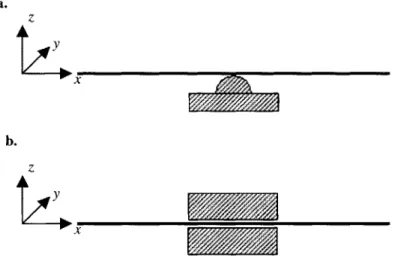
The second use of compliant parts is to assemble two or more compliant parts into a rigid
subassembly that is then used as a structural, load-bearing component. A good example
of such use is joining of two sheet-metal stampings to produce automobile frame rail.
Such resulting subassembly of compliant parts must have sufficient strength and rigidity
to achieve its function. Geometric relationship between the parts involved is typically not
particularly important. Rather, material properties of the resulting subassembly are of
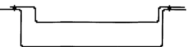
Fig. 3.1 Structural component assembled from two compliant parts.
Here, two stamped sheet metal parts are assembled together to form a box beam. The geometric relationship between the two parts is not important, as long as they form a box beam of sufficient stiffness. There is a "material property requirement" on the resulting assembly, but no "geometric
requirement".
The motivation of this thesis is to develop optimal methods of KC delivery through
compliant parts. Therefore, we will focus on the examination and analysis of the first, or "geometric requirement based", use. The second, or "material property requirement", use
is best handled during the detailed part-design process and is outside the scope of this
thesis.
3.2 Compliance of a part
Many types of compliant parts are in use in the industry. In this section, we will take a
closer look at compliance and study several properties of compliant parts.
3.2.1 Directions of a compliant part: flexible vs. rigid
Part compliance is a function of direction. While some parts, such as cloth patterns in the
garment industry, are equally compliant in all directions, more typically a compliant part
can deform much more readily in certain directions than others. This fact was discussed
in [Villarreal and Asada, 1991] in the context of robotic assembly of compliant work
If an equal force is applied in each direction, a compliant part deforms more readily in
certain directions than others. Based on material properties and part shape, certain
direction or directions will provide an easy mode of deformation [Panton and
Van-Brunt]. Deformation in such directions will be dramatically more pronounced, and
relatively small force input will be required to produce large deformation. Such direction
is called "flexible" direction of a compliant part. Direction that does not provide an easy
mode of deformation is called "rigid" direction of a part. A rigid part has six "rigid"
directions.
Concepts of compliance and rigidity are closely dependent on the size scale of
deformations due to applied forces. Nothing is perfectly rigid. But, depending on the
industry and product, part deformations of certain magnitude are judged negligible. The
level of these "negligible" deformations is what distinguishes a rigid direction from
compliant. Within the scope in any industry or product, one can safely assume that it does
not present a challenge to determine within what range of small deformations a direction
is considered "rigid". What's more, parts used in the industry have directions that can
easily be qualified as either "flexible" or "rigid" based solely on knowledge of material
properties and visual inspection of part shape, as well as designer's experience, as was
observed in [Villareal and Asada, 1991].
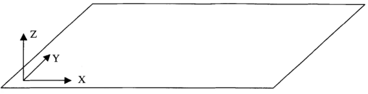
Plane of the part perpendicular to the flexible direction will be referred to as the "flexible
plane" of the part. For example, if a part's flexible direction is z, then the plane that lies
AZ
X
Fig. 3.2 Flexible direction of a compliant part and the associated flexible plane Flexible plane of the part is a plane perpendicular to its flexible direction.
Here, if Z is the flexible direction of the part, the associated flexible plane is the X-Y plane.
3.2.2 Types of compliance
Depending on material properties and part shape, compliant part's flexible direction can
be further subdivided into either of two compliance types - "semi-rigid" and "fully-compliant". In flexible direction, if all deformations due to unintended (by designer)
external factors - such as gravity or part handling - are non-existent or small enough to be discounted, that flexible direction is called "semi-rigid". In a semi-rigid direction of
the part, any part deformation will only occur due to locating features deliberately put in
by the designer. In other words, in a semi-rigid direction, any factor affecting the location
and shape of the compliant part is intended by the designer. Typically, a part with a "semi-rigid" direction will have at least one rigid direction as well.
If a part in a certain flexible direction can experience deformation due to unintended
external forces, such as gravity, in addition to intended locating features, that direction is
Distinction between semi-rigid and fully-compliant types of flexible directions depends
on material properties and shape of the part, as well as the part's orientation in space
relative to factors which can have unintentional influence on the part. Effect of the part's
orientation in space will be seen in the example discussed in the next paragraph.
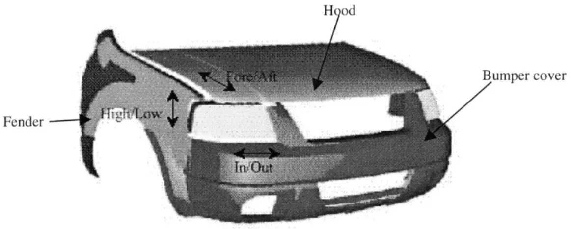
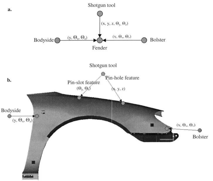
Let us examine the parts in the automotive front end assembly in Fig. 3.3. The fender has a clearly identifiable "flexible" In/Out direction. The remaining two directions - Fore/Aft and Up/Down - are rigid for most typical fender designs. Typical fenders have material properties and shapes that would have the In/Out direction be acting as "fully-compliant"
if gravity was acting in the direction parallel to In/Out. Thus, the In/Out direction of the
fender would be a "fully-compliant flexible" if the fender was assembled to the rest of the
vehicle in such a manner as to allow gravity to act in the In/Out direction - e.g., the car was being positioned on the assembly line on its side. However, the fender is usually
assembled with the vehicle positioned in the upright manner, with the gravity acting in
the Up/Down direction. With no other unintentional factors affecting the fender in the
In/Out direction, the designer can deduce that the fender has "semi-rigid" flexible In/Out
direction and two remaining directions are rigid.
A part can have flexible directions of more than one compliance type. For example,
depending on its exact shape and material, the plastic bumper cover of Fig. 3.3 might
have a rigid In/Out direction, a "semi-rigid flexible" Fore/Aft direction, and a
H od
Bumper cover
Fender
Fig. 3.3 Automobile Front End.
The three parts in the figure - fender (In/Out), hood (High/Low), and bumper cover (Fore/Aft and Up/Down), all have flexible directions.
Distinction between two types of compliance becomes important when KCs are delivered
through the compliant part in the particular flexible direction. It is important to realize the
effects of the different behavior of the two types of compliance. Since in a
fully-compliant direction unintended part deformations are possible, the part shape in that
direction is not fully controlled by the designer. Thus, KC delivery across a
fully-compliant direction is less predictable than in a semi-rigid direction. This will influence
designer's decision on placement and type of incoming mates to the part in the flexible
direction being considered. This topic shall be addressed further when concept of
Effective Locating Zone is introduced in Chapter 6.
3.3 Assembly as a removal of degrees of freedom
One way to think about the act of assembly is as removal of degrees of freedom from the
part being assembled. During assembly, free degrees of freedom are fixed relative to
Let us explore this concept by examining removal of degrees of freedom during the
traditional 3-2-1 part fixturing method (for more on the 3-2-1 fixturing method itself, see
[Lowell, 1982]). Rigid part assumptions are used. Ideally - assuming nominal dimensions
- all of the locating surfaces on each plane are engaged simultaneously. So, in the primary plane, the three locating surfaces engage simultaneously, instantly constraining
one translational and two rotational degrees of freedom. The three surfaces essentially act
as one feature. Similarly, on the secondary dimension, the two locating surfaces engage
simultaneously, acting as a single feature and instantly constraining one translational and one rotational degrees of freedom. The tertiary case is trivial, as only one locating surface
is involved.
However, with manufacturing variations and assembly variations from previous steps,
such ideal case of ideal parts is unlikely. Correspondingly, immediate engagement of all
locating surfaces in a given dimension will not occur. Let us explore what actually occurs
during 3-2-1 fixturing with part variations included. Upon contact of fixture with primary
plane of the part, the first locating surface to engage will constrain the translational
degree of freedom, second surface to engage will constrain one of the rotational degrees
of freedom, and the last surface to engage will constrain the remaining rotational degree
of freedom. Similar situation occurs with the secondary part plane. The first locating
surface to engage will constrain the translational degree of freedom, and second surface
to engage will constrain the remain rotational degree of freedom. The tertiary plane case
Examining the order of sequential removal of degrees of freedom during assembly
highlights the problems with redundant locators and overconstraint. Consider use of 4-2-1
fixturing in place of conventional 3-2-1 approach, with rigid part assumptions still in
place. Upon contact of the fixture with the primary plane, the first three locating surfaces
to engage the part result in behavior described previously. However, engagement of the
fourth locating surface creates problems. Either this fourth locating surface is redundant
and plays no role in constraining the part being assembled (thus raising a question about
its purpose in the first place), or the fourth locating surface influences the constraint, and
correspondingly location, of the part - resulting in an over constrained part - and disturbs the job done by the three locating surfaced already engaged. Such instances result in lack
of robustness in the final product. There is ambiguity about the role of each of the
features in locating the part. One is not sure which three of the four locating surfaces are
involved in locating of the part, thus resulting in uncertainty about the final location of
the part following assembly. This case can be extended to all situations where redundant
locators and overconstraint are present.
Compliant parts present an additional challenge to the analysis of degree of freedom
removal. Due to inherent nature of compliance, these parts may have additional degrees
of freedom associated with their flexible directions. As each locating surface engages the
part's flexible plane, it forces the part to deform. Each of the locating surfaces essentially
ends up single-handedly constraining and locating a small region of the part. The size and
shape of such regions depends on the interaction between all engaged locators. Situation
factors - usually gravity - influence the shape of the part. N-2-1 fixturing method [Cai et al., 1996], with N>3, is often used to minimize part deformation due to external factors.
Use of N locators results in the flexible plane of the part being divided into N number of
smaller regions, each controlled by one of the N locators.
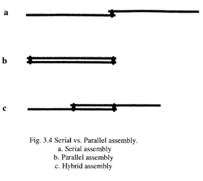
3.4 Different types of assembly of compliant parts: serial vs. parallel
[Liu et al., 1996] has split assemblies of compliant parts into two categories: assembly in
series and in parallel. Examples of both types of assemblies are shown in Fig. 3.4(a, b).
An assembly is serial if the two parts are joined "end-to-end", in such a manner that their
flexible planes are added to form resulting subassembly with a larger flexible plane, as in
Fig 3.4(a). If the two parts are assembled in such a manner that their flexible planes do
not add to form a larger flexible plane of the resulting assembly, as in Fig 3.4(b), the
assembly is in parallel. In other words, in serial assembly the flexible planes of parts
involved are added to one another, while in parallel assembly they are superimposed on
one another.
Fig. 3.4(c) shows an example of a hybrid case, an assembly that features characteristics
of both serial and parallel assembly. In such a case, the parts involved should be
examined and the decision on assembly type be made depending on the region where KC
delivery chain or chains pass through. Chapter 5 will discuss location of points
a
b
-C
Fig. 3.4 Serial vs. Parallel assembly. a. Serial assembly
b. Parallel assembly
c. Hybrid assembly
Note that notion of parallel assembly is only valid in case where parts involved have one
dimension significantly smaller than the remaining dimensions. This makes sense, as
such part shape is inherent to compliant parts with at least one flexible direction. The
distinction between serial and. parallel assemblies, while potentially applicable to all
parts, is particularly important to the discussion of compliant parts.
The major distinction between the two different types of assembly is in the rigidity of the
resulting subassembly: assembly in parallel will result in a subassembly that is more rigid
than either of the two parts involved, while the assembly in series will result in a
subassembly that is less rigid. One way to recognize the effect of these two assembly
methods is by treating the compliant parts as linear springs. If two parts are represented
by linear springs with coefficients of stiffness k1 and k2, the resulting coefficients of
stiffness for the resulting subassembly are: . . . ... .
-Kseries = (1/ki+1/k2)I
if the assembly is carried out in series, and
Kparraiei = ki+k2
if the assembly is parallel.
3.4.1 Assembly of compliant part and resulting rigidity
Rigidity of the final assembly is a function of nominal design. However, the rate at which
this rigidity is achieved is a function of assembly sequence chosen. As was shown in the previous section, choice between serial and parallel assembly steps has large influence on
the rigidity of the resulting subassembly. Any nominal design has within it a finite
number of serial and parallel assembly steps. By choosing a specific sequence in which these steps are performed, one can then influence the rigidifying rate of the assembly. Let
us explore a simple example of one large and two small sheet metal panels (Fig. 3.5).
Two possible assembly sequences are shown in Fig. 3.5(a,b), with the resultant graphs of assembly rigidifying in Fog. 3.5(c,d). Not surprisingly, with parallel assembly steps
performed first, the assembly is rigidified quicker. Similar conclusion is presented in [Hu,
1997].
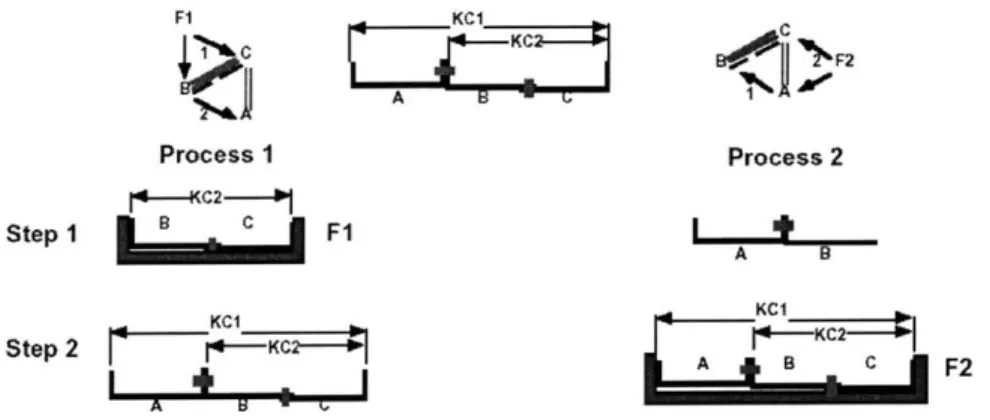
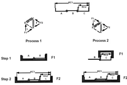
3.5 Rigidizing assembly step
Of particular interest to us is the assembly step at which locational and constraint
responsibility through a compliant part are set. This is the step after which all of the
degrees of freedom of the part have been constrained and the part essentially can be
problems nor advantages present due to compliance are of concern. Such a step is called
the "rigidizing" assembly step for the part.
a. Process 1: PS b. Process 2:
P U
0 ER *
First step (serial assembly)
0 +6
First step (parallel assembly) P
6
M
Second step (parallel assembly) 1 0.8 0.6 0.4 0.2 0
Second step (another parallel assembly)
- - - -Process 1 Process 2
0 1 2
Assembly Step
Fig. 3.5 Effect of assembly sequence on assembly rigidifying rate.
All beams are homogenous, having identical material properties and crossections. Stiffness is measured by clamping the subassembly at one end, applying force P at the other end, and measuring resulting end
deflection 6. Stiffness is then the ration of P/ S.
a. Process 1: serial assembly step is carried out first, parallel assembly step second
b. Process 2: both steps are parallel assemblies
c. Assembly stiffness throughout each process, normalized to final assembly stiffness.
By performing parallel assembly steps prior to serial assembly steps, the assembly stays more rigid
during the assembly and achieves its final rigidity state quicker.
Rigidizing step is of critical importance for analysis utilizing DFC methodology. During
this step, all locational and constraint responsibility paths - which will become links of the DFC - are established. Prior to this step, these paths cannot be established as the part is compliant and has under constrained degrees of freedom. Following this step, these
C. 0 .0 0 0 0 C M WWMWWWIW .
subsequent assembly steps. Thus, all locational and constraint responsibility paths
essential for top-down design with DFC are established during the rigidizing step.
Rigidizing step is the first assembly step where the compliant part is assembled in parallel
with another part or subassembly to produce a rigid result. Typical rigidizing steps
include a compliant part being added to a rigid subassembly, such as a fender installed to
the rigid car body frame. Another example is two compliant parts being brought together,
with a rigid fixture providing for all locating and constraint, to form a rigid component.
Examples of this included assembly of compliant sheet metal stampings into an
automotive rail assembly and assembly of door inner and door outer panels into an
automobile door.
Rigidizing step could be difficult to pinpoint for some parts in analysis of existing
assemblies. Clearly, a compliant part added to a much more rigid frame is a rigidizing
step, but such clear-cut steps are not necessarily always present. The step involving a
much more rigid frame could be lacking, or if the compliant part was involved in
previous assembly operations, it might be possible that one of the previous steps was in
fact a "rigidizing" step. The problem of clearly identifying the rigidizing step in early
stages of product development is further exacerbated by the lack of detailed knowledge
about parts involved - their exact geometries and material properties.
The solution to this dilemma is quite obvious and lies within the spirit of top-down
Just as designer can use DFC methodology to devise the exact paths of KC delivery, the
designer can also plan the exact assembly step at which locational and constraint
responsibility paths through a compliant part are made. The selection of the rigidizing
step thus becomes a tool of the designer, with the rigidizing step being chosen to optimize
KC delivery.
In certain cases, a compliant part may never undergo a rigidizing step, and retain at least
one flexible direction. In such cases, no KCs are to be delivered through the part in its
flexible direction. It can be argued that in these cases the designer either makes a mistake
(which, of course, must be corrected), is not concerned with that direction since no KCs
are delivered through it, or actually desires compliance in order to deliver a certain
function. For example, the diving board requires a flexible direction in its final assembled
state in order to function properly.
3.5.1 Choosing optimal rigidizing step
Chapter 4 will establish overconstraint of a compliant part as a means of resolving KC
conflict. In order to do so, the part must remain as compliant as possible until the final
step involving the part in KC delivery - assuming that KCs are delivered in the part's flexible direction. Thus, the optimal rigidizing step would be the assembly operation in
which the KC's are delivered through the part and ideally should be the last step
If no KCs are delivered in part's flexible direction or directions - either KCs involving the part are delivered through its rigid direction, or the part is not involved in KC delivery
at all - the selection of the rigidizing step is irrelevant from the point of DFC method. However, if the part is involved in delivering any sort of structural function, it would be a
good idea for a part to be rigidized early, though this area is beyond the scope of this
thesis.
Care should be paid to insure that the step designated by designer as rigidizing is indeed
the step that rigidizes the part. During detailed part design (following the overall
assembly design and establishment of rigidizing steps), it should be ensured that no steps
prior to the designated rigidizing step can unintentionally "rigidize" the part too early. In
addition, the rigidizing step itself should be examined to make sure that it provides
sufficient rigidity in the resultant assembly to properly "rigidize" the part.
3.6 Springback
Spring back is a well-known problem occurring during assembly of compliant parts.
Effect of spring back on the resulting assembly has been discussed by such researchers as
[Hu, 1997] and [Chang and Gossard, 1997]. Spring back occurs when fixtures, used in
the assembly to constrain a part in its flexible direction, are removed.
When the part is over constrained in its flexible direction, it deforms due to the
manufacturing and assembly variations present. As a result, internal stress is stored