The Design of the Housing for Leak Detection Device
byNaomi W. Zabel
SUBMITTED TO THE DEPARTMENT OF MECHANICAL ENGINEERING IN PARTIAL FULFILLMENT OF THE REQUIREMENTS FOR THE DEGREE OF
BACHELOR OF SCIENCE IN MECHANICAL ENGINEERING AT THE
MASSACHUSETTS INSTITUTE OF TECHNOLOGY JUNE 2011
@ 2011 Naomi W. Zabel. All rights reserved.
The author hereby grants to MIT permission to reproduce
and to distribute publicly paper and electronic ARCHIVEs copies of this thesis document in whole or in part
in any medium now known or hereafter created.
Signature of Author:
Department of Mechanical Engineering May 6, 2011 Certified by:
Sanjay barma Director of MIT-SUTD Collaboration
Thesis Supervisor Accepted by:
John4. jefflra v Samuel C. Collins Prefgsgogrglechanical Engineering
The Design of the Housing for Leak Detection Device
byNaomi W. Zabel
Submitted to the Department of Mechanical Engineering on May 6, 2011in the partial fulfillment of the requirements for the Degree of Bachelor of Science in Mechanical
Engineering
Abstract
Small leaks in pipes cause huge losses of water, wasting the energy and money put into cleaning the water and pumping it to the point of the leak. Detecting these small leaks is currently not very accurate or practical to do over an entire system of pipes. A device is being developed which detects leaks from within the pipe using the drop in pressure at the point of a leak. This thesis addresses the geometric needs for deploying the sensors in the pipe. The housing for the device needs to navigate pipes while keeping the sensors close enough to the wall to get a good reading. The housing is made up of a frame with flexible cantilevers which sensor holders pivot about to stay flush with the wall. After looking at other devices which navigate pipes, the geometric constraints of the pipe were used to create an initial design. The first iteration was manufactured to check for validity of the design. Many changes have to be made to the design based on the results from manufacturing the first iteration.
Thesis Supervisor: Professor Sanjay Sarma Title: Director of MIT-SUTD Collaboration
Acknowledgements
I would like to thank my thesis advisor, Professor Sanjay Sarma for giving me the opportunity to do this thesis. I would also like to thank my thesis supervisor, Stephen Ho, who guided me through creating the design and writing this thesis. Without his patience, help, and advice this thesis would not have been possible. I would also like to thank Isaac Ehrenberg for his assistance in making the prototype.
Table of Contents Page Number
Abstract...3
Acknow ledgem ents... 5
Table of Contents ... 6
List of Figures... 8
List of Tables... 9
Chapters --1. Introduction ... 10
1.1 W ater Leaks in Pipes and Current Solutions... 10
1.2 Project Overview... 10
1.3 Housing Design Overview... 10
2. Fram e Design... 12
2.1 Introduction... 12
2.2 Specifications... 14
2.2.1 M axim um Force... 14
2.2.2 M inim um Force... 16
2.2.3 Calculation of Force and Deform ation... 17
2.2.4 Calculation of Stress... 18
2.2.5 Device Diam eter... 19
2.3 Design... 20
2.3.1 M aterial ... 20
2.3.2 Cantilever Angle ... 21
2.3.3 Cantilever W idth... 22
2.3.4 Cantilever Length and Thickness... 23
2.3.5 Support Cylinder O uter Radius... 24
2.3.6 Support Cylinder Inner Radius... 24
2.3.7 Support Cylinder Length... 24
2.4 Design Sum am ary... 25
3. Sensor Holder Design... 26
3.2 Design of. Ouw...a ... 27
3.2.1 Radius of Outward Face ... 27
3.2.2 W idth to.Cantr... .... ... ... 27
3.2.3 Thickness ... ... ... 28
3.2.4 Length ...of Sen.... ... ... 28
3.2.5 Attachment to Cantilever..na.A...29
3.2.6 Placement of Sensor... . ... 31
3.2.7 Attachm ent of Sensor... 31
3.2.8 Reduction of Cross Sectional Area... ... 31
3.2.9 Curvature of the Front End ....the .ant.ev... 32
4. Initial Prototype ...ri r[ir ... 33
4.1 Introduction SlpFto.atlesi...33
4.2 Stress Concentration Point in the Cantilevers... 33
4.3 Sensor Holder Dimensions ... 34
4.4 Slip Fit of Cantilevers into the Sensor Holders... 37
4.5 The Cylindrical Portion of the Frame... 38
5. Conclusion... 38
F utu re W o rk ... 39
A . A p pen d ix ... 40
A.1 Fram e D im ensions... 40
A.2 Sensor Holder Dimensions...41
List of Figures
Figure 1.1. Design for the housing to hold the sensors... 11
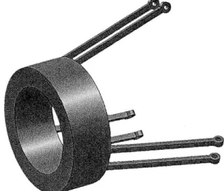
Figure 2.1. Central Support with cantilevers... 12
Figure 2.2. The dimensions of the cantilever and frame... 14
Figure 2.3. The model used to make the calculations for the maximum force... 15
Figure 2.4. The maximum force that can be exerted by the cantilevers on the wall versus the angle of the cantilever...16
Figure 2.5. The basic set up of the model for the calculations... 17
Figure 2.6. Model of a simple device going around a corner... 19
Figure 2.7. Device diameter versus maximum length that would not get stuck going around a corner... 20
Figure 2.8. Angle versus how it multiplies the force... 22
Figure 2.9. Force to deflect the tip of the cantilever the maximum predicted amount versus the thickness of the cantilever over a range of lengths... 23
Figure 3.1. The sensor holder design... 26
Figure 3.2. The shape of the outer face of the device... 27
Figure 3.3. The cross section for holding a single sensor... 28
Figure 3.4. A device going down a pipe... 29
Figure 3.5. The three options for cantilever to sensor holder attachment... 29
Figure 3.6. The set up of the sensor hold and the frame attachment... 31
Figure 3.7. The cross sectional area of the sensor holder... 32
Figure 3.8. Curvature at the front end of the sensor hold... 32
Figure 4.1. Prototyped frame... 33
Figure 4.2. The seams where the cantilever hit the cylindrical portion of the frame...34
Figure 4.3. The printed sensor holder prototype... 36
List of Tables
Table 1.1. Design requirements and corresponding features...11
Table 2.1. Pugh chart for material selection... 21
Table 2.2. Summary of frame design... 25
Table 3.1. Design requirements and corresponding features for sensor holders...26
1 Introduction
1.1 Water Leaks in Pipes and Current Solutions
In the United States, 6 billion gallons of water are lost daily (approximately 14% of water withdrawn daily).Il This loss costs a lot of money and energy on cleaning the water and pumping it to the point where it is lost. It can also negatively affect the environment surrounding the leak. Currently leaks are very difficult and expensive to find, so often go unfixed. It is not practical to dig up the pipes to look for the leaks. 1.2 Project Overview
The device being designed will detect leaks from within the pipe. It will find leaks by detecting a difference in water pressure created by the leak. In the majority of the pipe, the pressure is very high, but at points where there are leaks the pressure drops as the water flows to the outside, which is at atmospheric pressure. This paper discusses housing for this device.
1.3 Housing Design Overview
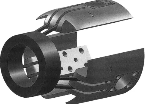
The housing for the device must be able to navigate pipes, which involves getting around corners, through junctions and over lips and bumps. The housing will also have to hold the sensors near the wall to get a good reading. The sensors should also not interfere with each other. The device should also be able to be propelled by the flow of water in the pipe. To achieve this, a design, shown in Figure 1.1, with a flexible frame and three separately pivoting sensor holders was created. The design requirements and corresponding features of this design are listed in Table 1.1.
Figure 1.1. Design for the housing to hold the sensors.
Design Requirement Feature
device must have a smaller diameter in order to
navigate corners, but a larger diameter to stay flexible cantilevers close to the wall the rest of the time
must not get stuck on bumps and lips curvature on the front of the sensor holders
pivot point in the center of the face of the sensor
face of sensor flush with the wall holder, keeps sensor against wall because the
front end is pushing back if starts to angle away will not be able to go down a pipe without having the length and width of the sensor holders create faces of sensor holders parallel to the wall a diagonal which is greater than 4 inches
sensor holder only able to move in radial direction pairs of cantilevers are used to connect to each sensor holder, rather than single cantilevers
manufacturable made from plastic
Table 1.1. Design requirements and corresponding features.
The housing is made up of a frame and three pivoting sensor holders. The frame is made up of a cylindrical portion with three pairs of flexible cantilevers. The
shape to go around corners and get over lips and bumps, but rigid enough to keep the sensor against the walls of the pipe. The sensor holders are attached to the cantilevers
by a rod which the sensor holders can pivot around. The pivot point is half way back into the sensor holder because having material on both sides of the pivot point will keep the sensor holders from tilting away from the walls. There are pairs of cantilevers to
ensure that the cantilevers do not deflect in the circumferential direction. The length and width of the sensor holders will not allow the device to travel down a pipe in an orientation where the sensors are not parallel with the walls of the pipe. The housing is
made out of a flexible plastic which can be 3D printed to make the device manufacturable.
2 Frame Design 2.1 Introduction
The goal of the device is to be able to navigate a pipe which is 4 inches in diameter while maintaining the sensor's position close enough to the wall to detect a leak using pressure changes. The challenges in doing this stem from variation in pipe diameter, bumps, corners and junctions. The housing must push out radially to maintain contact with the pipe walls, while still being flexible enough not to snag or snap when the diameter of the pipe changes. The device should not block the flow of the water in the pipe. To meet these parameters, a design that has cantilevers coming off the back of a hollow cylindrical frame with faces that can rotate on the ends, as shown in Figure
2.1, was chosen.
As shown in Figure 2.1, the cantilevers are integrated with the cylindrical portion of the frame. Benefits of integrating include easier assembly and a more secure connection to the cantilevers. The six cantilevers which come off the back of the cylindrical portion of the frame at 150 angle. The cantilevers are paired to make them more rigid in the circumferential direction while still being able to deflect radially. The pairs are spaced evenly to ensure that the force is spaced evenly around the device. The even spacing of the three pairs of cantilevers should also center the device in the pipe. The place of attachment to the sensor holder is behind the cylindrical portion of the frame to minimize interference with the sensors.
The cylindrical portion of the frame is hollow to reduce the interruption of the flow in the pipe. In the future, it could be made thicker to increase rigidity. Adding to the cross sectional area would also increase the force pushing the device. The frame may
not stay centered in the pipe. This feature will allow the device to navigate corners. The sensor holders are not integrated with the frame. If the sensor holders were integrated with the frame, the faces of the sensor holders would not stay flush with the wall. To attach the sensor holders to the cantilevers, the end of each cantilever has a through hole (0.125 inches in diameter) for a pin which the sensor holder will be able to pivot on.
The specifics of the cantilever need to be optimized to deal with the design requirements of the device. The sections below look at the forces constraining the design and optimize the material selection, diameter constraints, and the angle, width, length and thickness of the cantilevers (shown in Figure 2.2).
Figure 2.2. The dimensions of the cantilever and frame that will be discussed include the maximum diameter (dm), the outer diameter of the frame (do), the inner diameter of the frame (di), the angle of the cantilever (8), width of the cantilever (w), length of the cantilever (1), and thickness of the cantilever (t).
2.2 Specifications 2.2.1 Maximum Force
The device is moved along the pipe by water pressure. The force pushing the device has been estimated to be about 10 newtons, or approximately 2.25 pounds. When there is a force pressing on the cantilever, it creates a tangential force. The sum of these forces on the cantilevers cannot be greater than the pushing force because this would mean the device would get caught in the pipe. Friction should not be a huge issue. The radius of the face of the sensor holders is greater than the radius of the pipe; only the edge of the sensor holders will drag along the walls of the pipe. Friction is ignored in the model used in this paper. Figure 2.3 shows the set up of the model.
Figure 2.3. The model used to make the calculations for the maximum force; FEp is the force pushing the device down the pipe, Fc is the force the the cantilever exerts on the wall, Ns is the number of sensors, and e is the angle the cantilever is bent relative to the frame.
The reaction to the force put on the wall by the cantilevers and the force pushing the device down the pipe can be balanced:
2-Ns-Fchorizontal = -FP (1)
2-Ns-Fc-sine = -Fp (2)
Fe = -Fp/(2-Ns-sinO) (3)
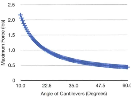
Currently, there are three sensors; the rest of the paper assumes that there are three sensors. In the future this number may increase, in this case there will need to be multiple rows of sensors and the calculations for the force that can be exerted will have to change. In Figure 2.4, the maximum force the cantilever can exert on the wall and still be moved down the pipe is compared to the angle of the cantilever for three sensors.
2.5 - 2.0 2 1.5 0 LL E M 1.0 0.5 0 10.0 22.5 35.0 47.5 60.0
Angle of Cantilevers (Degrees)
Figure 2.4. The maximum force that can be exerted by the cantilevers on the wall versus the angle of the cantilever.
The amount of force which can be applied by the cantilever on the wall without inhibiting device from moving down the pipe depends on the angle of the cantilevers. The angle is further discussed further in Section 2.3.3 and the maximum force is
indicated there. 2.2.2 Minimum Force
There is a minimum force that the cantilever should be able to withstand without deflecting, which comes from the weight of the sensor holder. If they cannot hold up the
sensors, the sensors will no longer be flush with the wall.
Fd = V-p (4)
Where FD is the force dragging the device down the pipe, V is the volume of the sensor holder, and p is the material density.
The density of FullCure 720 is 0.0395 lbs/in3, and the volume is approximately eight cubic inches. This makes the weight of each sensor holder 0.316 pounds. The weight of the sensor itself will not be more than a tenth of a pound. For this reason, the estimated total weight, and the minimum force that the cantilever should exert on the wall, is 0.400 pounds.
2.2.3 Calculation of Force and Deformation
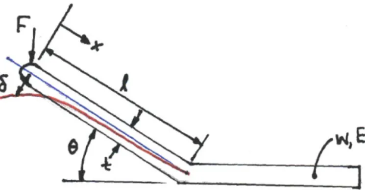
The dimensions of the cantilever are determined by how those dimensions affect the load needed to bend the cantilever. In order to calculate the force necessary to deflect the cantilever, the cantilever is modeled as a beam with a force applied to one end. The variables are shown on Figure 2.5.
F
Figure 2.5. The basic set up of the model for the calculations. x is the distance from the tip of the cantilever, F is the force at the end of the beam exerted upon it by the wall, 8 is the original angle of the cantilever, E is the Young's modulus, and I is the moment of inertia.
M = d62/dx2 = -Fcos~x/(EI) (5)
A= d6/dx = -FcosOx2/(2EI) + C1 (6)
& = -FcosOx3/(6EI) + C1X+ C2 (7)
Where M is the moment applied on the beam, AO is the angular deflection, and 6 is the deflection of the beam. [2] The other terms are described in Figure 5.
The values of C1 and C2 depend on the boundary conditions. There will be no change in angle or displacement at that end of the cantilever attached to the cylindrical portion of the frame:
at x = 1, AG = 0 (8) 0 = -Fl2cos9/(2EI) + C 1 (9) Ci = F12cose/(2EI) (10) and at x = 1, 6 = 0 (11) 0 = -Fl3cos9/(6EI) + Fl3cos9/(2EI) + C2 (12) C2 = -Fl3cos9/(3EI) (13)
From this the equation for deflection is:
6 = -Fcos/(6EI).(-x3 + 312x - 213) (14)
The value for the moment of inertia (1) is dependent on the width (w) and the thickness (t):
I = w-t3/12 (15)
This can be put into the equation above and get a more complete look at the equation for deflection as it depends on all of our variables:
6 = -2Fcos/(Ewt3).(-x3 + 312x - 213) (16)
This equation can also be looked at in terms of force:
F = -Ewt36/(2cosG(-x3 + 312x - 213)) (17)
These equations will be used in Sections 2.3.2, 2.3.3, and 2.3.4 on to decide what the dimensions of the cantilever should be in order to create a design that will meet the requirements of the system.
2.2.4 Calculation of Stress
The cantilevers must be able to withstand 1.5 pounds of force without fracturing. The yield strength of FullCure 720 is between 11600 psi and 16000 psi. [3] The greatest amount of stress at any point in the cantilever is
amax = MC/ (18)
where cmax is the maximum stress, M is the moment, c is the point farthest from the neutral axis of the cantilever, and I is the moment of inertia. The moment is given by the equation
M = Fx (19)
where F is the force applied, and x is the distance from the end of the cantilever where the force is applied. The neutral axis of the cantilever is the center of the thickness of
cantilever, therefore
c = t/2 (20)
where t is the thickness of the cantilever. The moment of inertia is given in equation 15. These equations give us an equation for the maximum stress in terms of the parameters of the beam
This equation will be used in Section 2.3.4 to see if the maximum stress that is expected to be exerted on the cantilever is will cause it to fracture.
2.2.5 Device Diameter
The device needs to be able to navigate a corner of a pipe which is 4" in diameter while still remaining near the wall. In order to determine these diameters, how
long the device could be over a range of diameters while still being able to go around a corner was calculated. For the most basic shape (one diameter throughout the device), the point where it would be the largest on the device, the diagonal, was compared that
to the diameter of the pipe:
dp = (dd2 + (1/2)2)1/2 (22)
where the diameter of the pipe is dp, the diameter of the device is dd, and the length of the device is I, shown on Figure 2.6.
dp dd
Figure 2.6. Model of a simple device going around a corner where diameter of the pipe is dp, the diameter of the device is dd, and the length of the device is I.
The maximum diameter the device can be and still navigate a corner is dependent on the length of the device. This relationship is shown in Figure 2.7.
,- 3 E 0 2 a) 0 0 1.75 3.50 5.25 7.00 Max Length
Figure 2.7. Device diameter versus maximum length that would not get stuck going around a corner.
The diameter when the cantilevers are unloaded must be greater than the maximum diameter of the piping (which can vary slightly, especially at corners and junctions) to insure that the faces of the sensors lay flush against the wall of the pipe at all times. The tips of the cantilevers are inscribed in a circle of radius 4.25 inches. Though this diameter is far larger than can go around a corner, the cantilevers will flex to compensate for the reduced diameter.
Once the length and angle of the cantilever have been determined, these assumptions will be used to decide the outer diameter and length of the frame as well as the length of the sensor holder.
2.3 Design 2.3.1 Material
The material of the frame must be flexible enough to deform with the pipe, strong enough to to not plastically deform, and rigid enough keep the faces flush against the wall. It is also important that it is easy to manufacture as well as reasonably priced and easy to obtain. In order to determine what material should be used, aluminum 6061, ABS, PVC, and FullCure 720 were compared, shown in the Table 2.1.
Criterion Al ABS PVC FullCure
Ease to Make (x2) - Datum 0
Price Datum +
Access to Material 0 Datum 0
Flexibility (x2) - Datum 0 +
Durability + Datum 0 0
Resistance to Plastic
Deformation Datum 0 0
Resistance to Fracture + Datum 0
Total -1 Datum -4 1
Table 2.1. Pugh chart for material selection (a "-" indicated not as good, a "+" indicated better, and a
"0" indicated about the same).
After doing the assessment above, FullCure 720 was chosen, which is a somewhat flexible plastic that is usually 3D printed. This will make it easier to make the cantilevers and frame one part while still fulfilling the other design requirements.
2.3.2 Cantilever Angle
The angle of the cantilever relative to the cylindrical portion of the frame affects the performance of the device. It affects the amount of force it takes to push the frame and the stiffness. The angle needs to be optimized to increase amount of force which the cantilevers can exert and not get caught and decrease the amount of force to deform the cantilever. With smaller angles, the cantilever will have to be longer to reach the wall of the pipe; this will make the device flimsy. The information presented in Figure 4 above was used as well as how the angle affects the force necessary to deform the cantilever, shown in Figure 2.8.
L 3.0 - - - -3.0 I 1.5- - - - -0 10 30 50 70 90 Angle (Degrees)
Figure 2.8. Angle versus how it rnultiplies the force. Force is related to one over the cosine of the angle, as shown in Equation 17.
In this iteration, a 150 angle will be used because it gives a reasonably high maximum force and a reasonably low multiplier of force. This means the maximum force that can be applied by each cantilever, as calculated in section 2.2.1, is
approximately 1.5 pounds. 2.3.3 Cantilever Width
The width of the cantilever affects the force must be used to deflect the cantilever, the area of connection to the other pieces and the amount the device interrupts the flow in the pipe. The width is proportional to the force that must be exerted on the cantilever, which makes it important, but means that it does influence the
length or the thickness (which are related by one over the cube and the cube respectively), as shown in Equation 17. Having a pair of parallel cantilevers creates more rigidity in the circumferential direction so there will be more resistance to bending in that direction than the radial direction. The width of each for this iteration will be 0.125 inches, and there will be a 0.375 inch gap between paired cantilevers because this gives rigidity in the circumferential direction while keeping the multiplier of force that it takes to deflect in the radial direction low.
2.3.4 Cantilever Length and Thickness
The length of the cantilever affects the force needed to deflect the cantilever and the diameter of the cylindrical portion of the frame. When the cantilever is longer, it is
more flexible, but rigidity is needed in order to be able to hold the sensor and exert a force on the wall. The outer diameter of the cylindrical portion of the frame is dependent on the length and angle of the cantilever, but the diameter is not a critical dimension for the design. It is discussed in a later section.
Both the length and the thickness are related by their cube to the force necessary to deflect the beam, shown in Equation 17. Multiple lengths for a range of thicknesses were compared in terms of how much force it would take to deflect the cantilever, shown
in Figure 2.9 with a close up of the acceptable range of forces on the right.
20 2.5 2 . '' 152.1 -1.7 t5) e10+ 1.3 o 0.100 0.138 0175 0.213 0250 0.10000.13750.17500.21250.2500
Thickness (in) Thickness (in)
+ length= 1.75 in 0 length = 2.00 in length = 2.25 in X length = 2.50 in A length = 2.75 in 0 length = 3.00 in + length = 3.25 in
Figure 2.9. Force to deflect the tip of the cantilever the maximum predicted amount versus the thickness of the cantilever over a range of lengths.
Since the force to deflect the cantilevers should be between 0.75 and 1.5 pounds, the length will be 2.5 inches with a thickness of 0.125 inches. Using equation 21, the maximum stress in the cantilever should be 11520 psi. This is slightly below the lower end of the range of yield stresses for FullCure 720.
2.3.5 Support Cylinder Outer Radius
The outer radius of the support cylinder, shown in Figure 2.2 is determined by the maximum radius of the pipe (Rpmax) and the angle (0) and length of the cantilever (l). Currently, the maximum radius of the pipe will be estimated at 2.125 inches, the angle of the cantilever is 150, and the length of the cantilever is 2.5 inches. From this the outer radius (RFO) was calcuated:
Rpmax - RFO = IcsinO (23)
RFO = Rpmax - losinG (24)
RFO = 2.25 - 2.5-sin(1 50) (25)
RFO ~1.45" (26)
Therefore, the outer diameter of the frame will be 1.45 inches. 2.3.6 Support Cylinder Inner Radius
The inner diameter of the device is calculated by subtracting the thickness of the device from the outer diameter. For the sake of having a small cross sectional area, but a reasonable amount of material, the thickness of the frame will be 1/4 of an inch. This means the inner radius of the frame will be 1.20 inches.
2.3.7 Support Cylinder Length
The length of the entire device must prevent the device from going down a pipe in the wrong orientation. The diameter of the pipes are around 4 inches, meaning the device must be at least 4 inches long so that it cannot go sideways down a pipe. This could happen in a T-junction if device was shorter than 4 inches. The sensor holders will be the longest part of the device and be the main prevention of this problem. The length of the cylindrical portion of the frame will be 1 inch unless it makes the device unable to navigate corners, which it should not.
2.4 Design Summary Attribute Decision Length of Cantilever (1) 2.5" Thickness (t) 0.125" Width (w) 0.125" Angle (0) 150
Inner radius (Ri) 1.200"
Outer radius (Ro) 1.450"
Length of Cylindrical Body (1c) 1"
Material FullCure 720
3 Sensor Holder Design 3.1 Introduction
The sensor holders must help the sensors get accurate readings as well as help the device navigate pipes. In order to get a good reading, the sensor must very close to the wall. This means the outward face of the sensor holder must stay as flush with the wall as possible. While staying close to the wall, the sensor holders should not get caught on bumps and lips in the pipe. The sensor holders must also ensure that the device cannot go the wrong orientation down a pipe. To achieve all these goals, the design shown in Figure 3.1 will be used. The following sections describe the design
and description of how the design was created.
Figure 3.1. The sensor holder design.
Design Requirement Feature
face of sensor stays close to wall curved outer face, explained 3.2.1
stays parallel with the wall connection to cantilevers is a pivot point at thecanter of the face, explained in 3.2.5
not block flow of water minimized cross section, explained in 3.2.8
can get over bumps and lips curvature at front end, explained in 3.2.9
3.2 Design
3.2.1 Radius of Outward Face
In order for the sensor to stay as close to the wall as possible, the outward facing side of the sensor holder is curved. The radius of the curve is the largest radius that is
likely to occur, 2.125 inches. The largest radius to occur is used because this ensures at least two points of contact at all times, which means it will be steadier.
3.2.2 Width
The device must be able to reduce in diameter in order to allow for bumps and corners, which decrease the area which the device can pass through. The three sensor holders together should create a minimum radius, 1.650 inches. The three sensor holders should be able to fit together without interfering with one another when going around a corner. The width of each sensor holder should be the length of the sides of a triangle inscribed in a circle with that radius. To figure out how wide this makes each sensor holder, the chord length of a 1200 angle in a circle with a radius of 1.65 inches was calculated. The chord length is 2.858 inches. An arc with the larger radius, 2.125 inches, with this chord length is the shape of the outward facing side of the sensor holder. The Figure 3.2 shows the dimensions of the arc of the outward facing side of the sensor holder and shape of the outside when the three sensor are held together.
2.86
)
3.2.3 Thickness
The sensor holder must be thick enough to house the sensor and have a lip that will be a base for the sensor to sit on and allow the leads to go out. The sensor holder must also be as thin as possible to limit interference within the device and obstruction of the flow in the pipe. The sensors are currently 0.75 inches thick, and the lip will be 0.10 inches thick. The sensors are 1 inch in diameter and will therefore be a little bit down from the top of the arc (0.05966 inches). This brings the total thickness to 0.9097 inches. The arc of the outer face has a depth of 0.5522 inches, meaning there is an additional depth of 0.3575 inches below the arc. The additional depth is angled in so the sensor holders do not interfere with each other. The resulting cross section is shown in Figure 3.3. The cross section can be reduced by cutting away unnecessary portions to reduce obstruction of flow within the pipe, this is discussed in section 3.2.8.
CDC oCL
Figure 3.3. The cross section for holding a single sensor.
3.2.4 Length
The length of the sensor holder must allow the device to round a corner and prevent the device from going down a pipe in the wrong orientation. From the calculations for length versus maximum ratio (Figure 2.7 from section 2.2.4), the maximum length to clear the corner with a radius of 1.65 inches is approximately 4.5 inches. The length of the sensor holders is 4 inches. There is the additional length added by the frame, but this should not cause the device to get stuck because it has a smaller radius. A 4 inch length should also make it so that the device cannot go down a
pipe in the wrong orientation because the width will make it unable to fit down a 4 inch diameter pipe, except with the sensor holders facing the wall, shown in Figure 3.4.
Figure 3.4. A device going down a pipe in the wrong orientation if it is too short. 3.2.5 Attachment to Cantilever
The attachment of the sensor holder to the cantilever and frame must be fairly easy to assemble and keep the outward face of the sensor flush with the wall. Initially, there were three options for how the sensor holder could be attached, shown in Figure
3.5.
(a)
(b)
(c)
Figure 3.5. The three options for cantilever to sensor holder attachment; (a) single piece, (b) end pivot with spring, (c) mid point pivot.
The first option is to make the sensor hold as a part of the frame (shown in Figure 3.5a). This would make assembly far more simple, but it would make it so that as the cantilever bent, the sensor would become farther away from the wall, as it would not change the angle at which it is connected. This would be a problem for getting readings.
The second option is to have a pivot with a spring that would push the sensor towards the wall (shown in Figure 3.5b). This would solve the problem of keeping the sensor flush will the wall, but would be difficult to assemble. Having a spring is also not ideal because it is metal which could interfere with the electronics, it could fatigue over time, and it could rust over time.
The third option is having the pivot point where the cantilever attaches be a little way back in the sensor hold so that the front of the face is also pushing against the wall, keeping the face flush with the wall (shown in Figure 3.5c). Though it will be harder to assemble than the first option, it will be easier than using a spring, and will keep the sensor as close to the wall as possible. This option was chosen because it satisfies the need to keep the face of the sensor holders against the wall while still being easy to assemble.
There will be two slots equally spaced from the center. The slot will be two inches in length. Having separate slots will ensure that the cantilevers stay separate and increase the rigidity in the circumferential direction. Each slot is as wide as the cantilever which will allow the hold to pivot around the cantilever. A pin will go through the cantilevers and keep them in place while allowing the sensor to pivot. The frame will not cause interference because the sensor hold will not go all the way to the cylindrical portion of the frame. This set up is shown in Figure 3.6.
Figure 3.6. The set up of the sensor hold and the frame attachment. 3.2.6 Placement of Sensor
The sensor is in the center located in the center of the region behind the pivot point. The sensor is in the center of the arc of the outward face to keep it as close to the wall as possible.
3.2.7 Attachment of Sensor
The sensor must be attached in a way that interferes as little as possible with the device's navigation. The sensor will be attached using four plastic screws holding a square rubber gasket which goes over the edges of the sensor. The screws will have a nut and washer on the inward facing side of the sensor holder in order to minimize the amount of material facing the outside wall. In future iterations this rubber gasket may have extra material going out over the face of the sensor holder to make a better seal; the sides could be pulled up to the wall when there is a leak, which create better readings.
3.2.8 Reduction of Cross Sectional Area
The cross sectional area of the device must be minimized to disturb the flow of water in the pipe as little as possible. All of the cross section except the center portion holding the sensor and lip 0.125 inches thick at the top were removed to decrease the area of the sensor holders. The result of this is shown in Figure 3.7.
Figure 3.7. The cross sectional area of the sensor holder. 3.2.9 Curvature of the Front End
While in the pipe, the device will encounter bumps either from build up on the wall, slight changes in diameter of the pipe, misalignment of pipes, and imperfections in the pipes. The cantilevers will be able to compensate for these changes, but in order to reduce the force needed to overcome these obstacles, the front end of the sensor hold is curved. This should make these transitions as small as possible. A 1.00 inch radius was used to make this curve for the outer face, while a radius of 0.25 inches for the inner face, and the resulting shape is shown in Figure 3.8. Theses radii where chosen as a starting point for testing.
R 1.00
R 0.25
4 Initial Prototype 4.1 Introduction
The first prototype of the housing of the device was 3D printed in FullCure 720. The model was used to find flaws in dimensions and structural integrity of the housing. Several issues were identified in this initial iteration. The cantilevers have a point of stress concentration where they all fractured, the dimensions of the sensor holders did
not stay true to the solid model, the slip fit tolerances were not large enough, and the cylindrical portion of the frame is unnecessarily bulky and heavy. These observations, the causes, and the changes that will be made in the next iteration are discussed in the following sections.
4.2 Stress Concentration Point in the Cantilevers
There is a large stress concentration at the base of the cantilevers where they meet the cylindrical portion of the frame. During the printing process, a pair of the cantilevers broke off at this point. The second pair was broken during assembly. The third pair broke off while observing the shape of the cantilevers during when being deflected. No exact measurements were taken of how much force was needed to have the cantilevers fail at this point. Figure 4.1 shows frame and cantilevers after breaking.
Figure 4.1. The frame fractured at the point where the cantilevers and the cylindrical portion meet.
This fracturing is caused by a large stress concentration. While the yield strength of FullCure is 11600 to 16000 psi, the maximum stress calculated along the cantilever was 11500 psi. This means the stress was very close to the breaking point at the
maximum that should have been reached in the pipe, but should not have broken. The additional stress caused by the seam and the probably application of pressure greater than that of the anticipated is the probably cause for the breaks. In the next iteration, in addition to the elimination of seams, there should be a larger safety factor to insure the cantilevers do not fracture. In this iteration there were square corners, as shown in
Figure 4.2, which made an uneven stress distribution.
Figure 4.2. The seams where the cantilever hit the cylindrical portion of the frame.
In the next iteration, the seams will be eliminated. There will fillets where the cantilevers meet the rest of the frame. There will also be material added to half of the cantilevers closer to the frame. The material will slope out in all directions as it gets closer to the rest of the frame and slope into the rest of the frame.
4.3 Sensor Holder Dimensions
Most of the dimensions of the sensor holder differ between the solid model and the printed prototype. This difference is probably caused by the material shrinking as it cools in the printer. The comparison of the solid model and the physical prototype are shown in Table 4.1.
Dimension Solid Model (in) Prototype (in) 0.910 0.908 2.860 2.854 3.950 3.924 1.000 0.986 0.275 0.260 0.200 0.195 0.130 0.120 0.750 0.744 0.130 0.125
Table 4.1. Comparison of dimensions of the solid model and prototype. Green indicates an acceptable difference; red indicates an unacceptable difference.
The overall height, width, length, and lead hole diameter are not critical dimensions and the slight difference from the model is acceptable. While the overall shape which these dimensions affect is important, the slight variation will not affect the function of the device. Similarly, the difference in the exact curvature of the outer face of the sensor holder will not affect the functionality of the device, and therefore does not need to be changed. The printed device is shown in Figure 4.3 as well as a comparison between the designed curvature and that of the prototype.
(b)
Figure 4.3. The printed prototype; (a) overall shape, (b) comparison to designed arc.
The dimensions for the hole which holds the sensor must be corrected. The diameter of the hole shrunk and must be made greater to account for the change to still have a slip fit diameter. The sensors could not fit into the hole, as shown in Figure 4.5. The hole will also be made deeper so that the sensor will not stick up above the surface. If the sensor sticks up, it will interfere with gasket which is supposed to secure it. It might also interfere with the device staying flush with the wall. The screw holes will also have to increased in diameter to create a slip fit for a screw.
Figure 4.4. The sensor would not fit into the hole intended for it.
The width slot for the cantilevers as well as the hole for the rod which allows the sensor holder to pivot are smaller than the model. The hole for the rod will be increased in size to account for this. The width of the slot will also be increased in size and is discussed further in Section 4.4.
The average amount of change was a decrease of 3%. For the next iteration, dimensions should be increased by about this much for critical dimensions. Dimensions that for slip fits may be slightly oversized beyond this because in this design they are still functional slightly oversized, but not functional if they are slightly too small.
In the future, the sensor holders could be made out of ABS rather than FullCure. FullCure was chosen because of it is less brittle than ABS for the frame, but this advantage is not applicable to the sensor holders. ABS is less expensive and should not affect the function of the device. The changes in dimensions will be different than that of the FullCure and more experiments will need to be done to determine how to get the right dimensions.
4.4 Slip Fit of Cantilevers into the Sensor Holders
The ability of the sensor holders to pivot about the end of the cantilevers is one of the key features of the housing. The cooling of the material caused the width of the slots to decrease. The cantilevers fit very tightly into the slots, but it was not a slip fit
and pressure needed to do this assembly caused the cantilevers to snap off. To create the slip fit, the slots could be made wider or the cantilevers could be made thinner. Making the cantilevers thinner would decrease the rigidity of the cantilevers as well as the security of the connection between the cantilevers and the cylindrical portion of the frame, therefore the slots in the sensor holder will be made wider. The slip fit needs to have a tolerance of at least 0.005 inches. The slip fit should not have a large tolerance because the slots are keeping the cantilevers parallel which creates the rigidity in the circumferential direction.
4.5 The Cylindrical Portion of the Frame
The cylindrical portion of the frame needs to be thick enough that it is rigid, but the prototype showed that the current model is thicker than it needs to be to have the rigidity the device needs. A thinner frame will decrease the cross sectional area and weight of the frame, which will decrease the amount of force necessary to push it down the pipe. The front of the frame can also be curved to make it more aerodynamic. The inner side can also be curved to create more area for the water to push against, which will create more force pushing the device. The cantilevers will be 0.15 inches longer moving and allow a larger range of motion, and to create a smaller outer diameter for the cylindrical portion of the frame. The place where the sensor holders meet with the cantilevers will be moved 0.125 inches further away from the wall. This means the outer diameter of the frame will be changed to 2.628 inches.
5 Conclusion
The goal of the housing is to keep the sensors close to the wall while navigating pipes. The device must be able to go around corners, over lips and bumps, and through junctions. To accomplish this, a design composed of a frame with three pairs of flexible cantilevers attached by a pivot point to three sensor holders was created. The initial design was then manufactured using 3D printing. From this first iteration, a number of flaws with the initial design were found. There was a stress concentration where the cantilevers meet the frame due to seams at those points. This will be addressed in the next iteration of the device by adding material to the base of the cantilever and creating a curved surface instead of having seams. Due to the manufacturing process, some of the critical dimensions of the sensor holders were too
different from the model to allow it to function properly. The dimensions of the solid model will be changed to account for these discrepancies between the solid model and the physical prototype. The material of the sensor holders will also change since the benefits of using FullCure over ABS do not apply to the part and ABS is significantly less expensive. The cylindrical portion of the frame uses far more material than is necessary and can be shaped differently to make it more aerodynamic. It will be made smaller and thinner and the front of the device will be curved. The next step is to try manufacturing another prototype which reflects the changes made to the design and to try this design in a pipe.
Future Work
The next step in this project is to make the changes to the design which are discussed above, and manufacture this new design. If the prototype has no obvious flaws, it should be tested in non-operating conditions in a pipe. The experiments should make sure that the device can navigate a corner, pass through a junction, keep the sensors close to the wall, and get over bumps and lips. Once this has been confirmed, the device should be tested under operating conditions. It should first be tested without the sensors to make sure the device navigates as it is supposed to under operating conditions. There is currently no place for housing electronics, which will need to be made in order to test the device with the sensors.
Appendix
A.1 Frame Dimensions
RO.0625" 0.125" R1.20 2.50" RO.1825" 11.45" 0.125" 150 1.00" 0.375"
A.2 Sensor Holder Dimensions 0.370" 0.130" R2.125"
0.125"
__1.25" 2.856" 0.91" 0.75" 1.50" 2.00" RO. 125" R1.00"" ISection View A-A
600 RO.10" R1 .00" RO.26" R1.20" ' RO.25"
Bibliography
[1] United States Environmental Projection Agency, Sustainable Infrastructure, "Water Efficiency & Conservation." Available from http://water.epa.gov/infrastructure/sustain/
wec wp.cfm (last updated December 16, 2010). Accessed May 5, 2011.
[2] Object.com, Digital Materials Data Sheet, "Simulating Standard Plastics." Available from http://www.objet.com/Portals/O/docs2/Digital%2OMaterials Datasheet A4.pdf. Accessed May 5,2011.
[3] Hibbler, R.C. Mechanics Of Materials. Upper Saddle River, New Jersey: Pearson Education Inc., 2008.