Passive UWB RFID for Tag Localization: Architectures and Design
Texte intégral
Figure
Documents relatifs
The problems of creating a regenerator of an optical system for trans- mitting discrete messages with the aim of protecting against the influence of in- tersymbol interference
We advocate a design methodology including high level specifications using the modularity and reusability features of the S IGNAL programming; formal verification and per-
In the next section, we only state that in case of trees, the Boolean dimension, geometric dimension and the minimum rank coincide, thus the formula given in Theorem 2.9 below for
Index Terms—TIM, wireless network, interference topology, DoF, interference threshold parameter, achievable symmetric rate..
This paper presents the evaluation of a passive tag-to-tag communication by considering the two tags as two mutually coupled antennas in Near Field and an external source in Far
i) electromagnetic coupling (i.e., the mutual coupling between the tags or the orientation of the tags with respect to the source); ii) modulation depth; iii) receivers
Figure 4 shows the modulated signal (point B on Figure 1) using DSB-ASK (Double- side band amplitude shift keying) modulation sent by the reader transmitter.. Digital data to
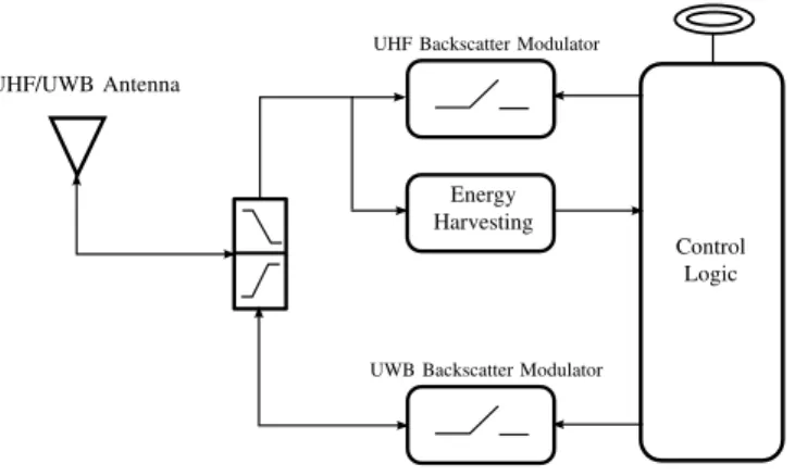
The reader consists in a transceiver, with an antenna that communicates with a passive tag.The tag returns by retro-modulationits identification code.The RFID
