HAL Id: in2p3-00986882
http://hal.in2p3.fr/in2p3-00986882
Submitted on 11 Jun 2019HAL is a multi-disciplinary open access archive for the deposit and dissemination of sci-entific research documents, whether they are pub-lished or not. The documents may come from teaching and research institutions in France or abroad, or from public or private research centers.
L’archive ouverte pluridisciplinaire HAL, est destinée au dépôt et à la diffusion de documents scientifiques de niveau recherche, publiés ou non, émanant des établissements d’enseignement et de recherche français ou étrangers, des laboratoires publics ou privés.
Distributed feedback lasing of commercial liquid
scintillators
M. Michel, L. Rocha, M. Hamel, S. Normand, J.C. Angélique
To cite this version:
M. Michel, L. Rocha, M. Hamel, S. Normand, J.C. Angélique. Distributed feedback lasing of commer-cial liquid scintillators. Optics Letters, Optical Society of America - OSA Publishing, 2013, 38 (24), pp.5307-5310. �10.1364/OL.38.005307�. �in2p3-00986882�
Distributed feedback lasing of commercial liquid
scintillators
Maugan Michel1,3, Licinio Rocha1,4, Matthieu Hamel1, Stéphane Normand1, and Jean-Claude
Angélique2
1CEA, LIST, Laboratoire Capteurs et Architectures Électroniques, F-91191 Gif-sur-Yvette, France 2LPC Caen, ENSICAEN, Université de Caen, CNRS/IN2P3, F-14050 Caen, France
3e-mail: [email protected] 4e-mail: [email protected]
Abstract
It is shown that lasing can be achieved in commercial organic liquid scintillators. Using a dynamic grating induced by an interference pattern in the scintillator volume, distributed feedback lasing is shown to occur in four out of five commercial liquid scintillators that have been investigated. Although these scintillators are not designed for lasing application, their purpose being to measure radioactivity, induction of a laser effect, furthermore with a tuning range of approximately 30 nm, has been attained.
Optical resonators such as the distributed feedback (DFB) laser [1] are to this day widely used in a variety of fields. Mainly developed for communication technologies [2], its use ranges from lab-on-chip devices [3] to Martian exobiology [4,5]. Photonics has recently been used in nuclear science, where it has been demonstrated that using photonic crystals can improve light extraction from scintillators [6,7].
Whether they are homeland security-, CBRN-E defense-, or contamination monitoring-related, nuclear instrumentation needs to rely on cheap and efficient sensing devices in order to be spread out. Scintillators are luminescent materials in which light is induced by the excitation and ionization provided by ionizing radiation emitted following radioactive decay [8,9]. Because they are fast and low-cost and can be manufactured into large quantities, organic scintillators have been chosen for our study.
A typical scintillator is made of a solvent/matrix (for liquid or solid scintillator, respectively), and a primary and a secondary solute/fluorophore. When an ionizing particle passes through a scintillator, it transfers some—and sometimes all—of its energy to the solvent. The typical linear energy transfer ranges in the keV to MeV/µm region. This energy is then transferred through a cascade process to the first and then secondary solutes, the latter emitting light when deexciting to the fundamental energy level. The emission spectrum should correspond to the maximum detection efficiency of the coupled photodetector(s) (around 420 nm for most of them). Because of this emission wavelength requirement, most of the scintillators’ wavelength shifters are either Bis-MSB or POPOP. The solvent must also be adapted to the kind of particle that is to be detected (e.g., alpha, beta, gamma, neutron), which itself depends on the radioactive sample.
It is this energy absorption and transfer, depending on the considered sample and radionuclide, that will determine the composition of a cocktail for liquid scintillation counting.
While a scintillating material will fluoresce, a fluorescing material may not fulfill scintillating criteria, which can be the case of laser dye doped polymeric materials or conjugated polymers. These materials are used for organic tunable lasers, but are not optimized regarding their scintillating properties. For instance, although it is a widely used laser dye, exposing a rhodamine 6G in ethanol solution to beta irradiation with a 23.1 MBq Sr90/Y90 radioactive source, we have not been able to observe any scintillation light. This is why scintillators, among
the most used nuclear measurement technologies, are here investigated regarding their lasing ability.
The samples are five different commercial liquid scintillators, each having a particular aim, here described:
• BC-501A/NE-213: (Saint-Gobain). Optimized for neutron/gamma discrimination.
• High-efficiency mineral oil scintillator: (Mineral Oil, PerkinElmer). Optimized for
Radon detection in water and soil samples.
• Pico-Fluo 15: (PF15, PerkinElmer). Specifically formulated for aqueous samples. • ProSafe FC+: (PSFC, Meridian). Designed for filter counting.
• Ultima Gold AB: (UGAB, PerkinElmer). Specifically designed for alpha/beta
discrimination.
The scintillating solutions were used as sold.
In order to determine the stimulated emission threshold, the linearity break in the output versus input excitation power is sought. Excitation of the samples is provided by a frequency-tripled (355 nm) 20 mJ pulsed picosecond Nd3+:YAG laser. Excitation beam energy is tailored
through a homemade continuous variable attenuator based on an adjustable waveplate paired with a polarizer. The 2.5 mm diameter 355 nm beam is then passed through a cylindrical lens, focusing the Gaussian-shaped beam into a (2.5×0.27) mm2 line onto the samples. This
focusing, as well as increasing the energy density, lowers the stimulated emission threshold, thanks to waveguiding effects. The samples are contained in a 2 mm optical path quartz cuvette, except for UGAB, for which the optical path is 10 mm.
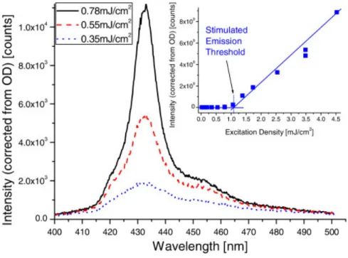
Both linewidth thinning and output versus input intensity linearity break have been observed when exciting most of the scintillators, the measurements for the ProSafe FC [10] scintillator being presented in Fig. 1.
Fig. 1. Emission spectra of the ProSafe FC liquid scintillator for different excitation energy
densities. The excitation beam is a (2.5×0.27) mm2 third harmonics (355 nm) of a picosecond
Nd3+:YAG laser, focused into a line. Inset: intensity of the light emitted for different values of
excitation energy density. Above the threshold of 1.09 mJ cm−2, the linebreak indicates
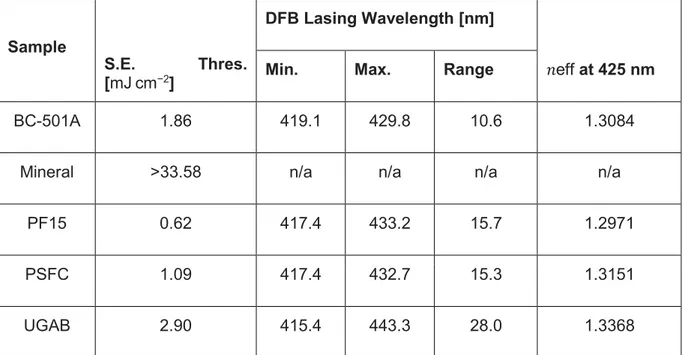
Table 1 lists the measured stimulated emission thresholds for these scintillators. The stimulated emission regime could not be reached for Mineral Oil, even at full beam power. Also, due to a limited resolution of this experimental setup and a very steep increase of the scintillator’s response, the UGAB threshold is overestimated.
Sample
S.E. Thres.
[mJ cm−2]
DFB Lasing Wavelength [nm]
eff at 425 nm
Min. Max. Range
BC-501A 1.86 419.1 429.8 10.6 1.3084
Mineral >33.58 n/a n/a n/a n/a
PF15 0.62 417.4 433.2 15.7 1.2971
PSFC 1.09 417.4 432.7 15.3 1.3151
UGAB 2.90 415.4 443.3 28.0 1.3368
Table 1. Stimulated Emission Threshold and DFB Lasing Values of the Commercial Liquid
Scintillators Obtained with the Current Experimental Setup(Effective refractive index values were obtained using Eq. (3) and data from Fig. 4(b))
Similar results were obtained by Abakumov et al. [11] and Broida and Haydon [12] in the 1970s, but although stimulated emission thresholds are only provided by Abakumov, no information is given as to how these were obtained.
Creating a periodic variation of the optical properties of a dielectric material at the optical wavelength scale changes the material’s light generation and propagation properties. Inducing gain, refractive index, or topography gratings will thus change the way light is absorbed and emitted and the way it propagates. A change in the diffraction behavior can also define privileged light channels, which, combined with a light amplification mechanism due to a primary amplification phenomenon, can lead to an important amplification of the output light. These abilities have been used to design prototypes for highly sensitive sensing devices [13,14].
Nanostructuration of a material can either be permanent or not. The first, based on material etching (e.g., by soft lithography [15]), does not suit our proof-of-concept investigation because of the time and material cost it implies. This is why transient grating structuration, allowing a real-time control of the periodic structure properties, has been chosen.
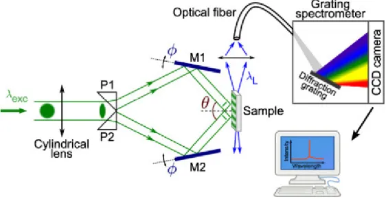
The experimental scheme used to create such transient grating is presented in Fig. 2. The same focused laser beam as in the previous experiment is used in order to lower the DFB lasing threshold, as observed by Dumarcher et al. [16]. It is then split by a system of two prisms and, after reflection on contra-rotating mirrors, interferes on the sample’s surface. Samples are contained in the exact same quartz cuvettes as for the stimulated emission experiment. Spectra are collected through a spherical lens into an optical fiber, and sent to a diffraction spectrometer (Acton SP-2300i spectrograph coupled to a Princeton Instruments PI-MAX intensified CCD camera). Optical densities have been used to attenuate the collected light. In
the present case, both excitation and modulation of the optical properties are provided by the exc=355 nmlaser beam (corresponding to the absorption spectrum of the samples).
Fig. 2. Schematic of the dynamic DFB grating experimental setup. The interference pattern
creates gain and refractive index gratings. Prisms are UV-grade silica. The contra-rotation angle of the mirrors is controlled through a linear translation stage. Materials are excited with the third harmonics (355 nm) of a picosecond Nd3+:YAG laser.
The sinusoidally varying intensity profile created by the interference pattern generates a combination of both gain and refractive index 1D gratings. Due to the optical Kerr effect, the refractive index varies as = 0+∆ , where 0 is the linear refractive index and ∆ is the
refractive index variation induced by the high-intensity optical field. Interfringe spacing, i.e., grating period Λ, is controlled by the intersection angle of the incident laser beams via
(1)
=
Optical feedback is provided by the scattered light in the periodically structured material when the Bragg condition is fulfilled for a defined diffraction order , as described by the coupled-wave theory presented by Kogelnik and Shank in the early 1970s [17]:
(2)
=2
effΛ/
where is the DFB lasing wavelength, and eff is the effective refractive index seen by the
waveguided mode.
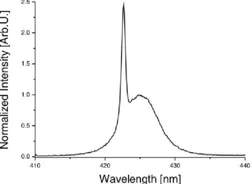
Figure 3 shows the effect of the optical periodical excitation performed on the ProSafe FC sample. A narrow emission peak is induced on the stimulated emission band when the Bragg condition is fulfilled. The energy from the stimulated emission continuum is channeled into the DFB laser emission, which has a narrower linewidth (described by the FWHM). As examples, the fluorescence, stimulated emission, and DFB lasing spectra’s FWHM values measured for UGAB and PSFC are 45∶25∶0.5 and 25∶6∶0.6 nm, respectively. In our configuration, DFB lasing occurs in the second order of diffraction [see Eq. (2)], which corresponds to a laser beam emitted perpendicularly to the interference fringes. As can also be observed from the DFB spectrum in Fig. 3, stimulated emission energy is not completely redistributed in the laser peak: there is a competition for the gain between lasing and nonlasing modes. Optical losses in the DFB system can partly be explained by a poor confinement of the propagating waves in the configuration here used and by an equipment-related inhomogeneous transient grating.
Fig. 3. ProSafe FC DFB lasing growing atop the stimulated emission continuum once the
Bragg condition is fulfilled. Excitation is achieved with the third harmonics (355 nm) of a picosecond Nd3+:YAG laser.
Eventually, because it is integrated into the gain medium itself, DFB makes DFB lasers much more stable, both mechanically and geometrically, as well as much more compact.
Our dynamic grating configuration also enables us to continuously tune the wavelength of the DFB laser by adjusting the interfering angle of the exciting/structuring beams as underlined by Eq. (3). The contra-rotating mirrors angle is controlled by a linear translation stage coupled to the mirrors’ rotation axis. Hence lasing wavelength, given by
(3)
=
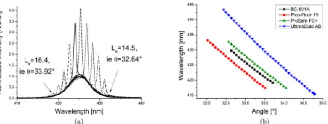
can be tuned according to the contra-rotation angle. Tuning of the four tested scintillators is presented in Fig. 4, with a focus on the DFB spectra of PSFC in Fig. 4(a). Their tuning ranges are listed in Table 1, except for Mineral Oil, for which stimulated emission threshold could not be reached.
Fig. 4. DFB lasing of the commercial liquid scintillators. Excitation is a 2.5 mm diameter, third
harmonics ( exc=355 nm) beam of a picosecond Nd3+:YAG laser, focused into a narrow stripe.
(a) DFB lasing spectra of the PSFC scintillator at different linear translation stage positions . The DFB lasing peaks grow atop the stimulated emission continuum. (b) DFB laser peak wavelength versus nanostructuring beam incident angle plot.
The plots of Fig. 4(b) show the lasing wavelength evolution according to this angle. Waveguided modes’ propagation constants must verify the Bragg condition for different interfering conditions. Hence the observed wavelength shift between the curves with an identical grating period is due to the effective refractive index eff, which is different for each
scintillator, as shown in Table 1, where its values at 425 nm are indicated.
This ability to trigger a laser emission in scintillating materials can have strong implications in the detection of nuclear particles and could lead to the definition of new strategies for the design of devices with improved sensitivity.
We have evidenced laser action in commercial liquid scintillators under the DFB regime with a maximum tuning range of 28 nm attained with Ultima Gold AB, spanning from 415 to 443 nm. Out of the five scintillators that have been tested, all but one (Mineral Oil) could achieve stimulated emission under our current experimental setup (picosecond, 20 mJ, frequency-tripled Nd3+:YAG laser). All scintillators that could achieve stimulated emission were able to
show lasing emission when subjected to a dynamic periodic modulation of their optical properties.
Scintillators are widely used in nuclear instrumentation, while their main drawback is their low light output when exposed to ionizing radiation. The lasing ability of the commercial scintillators demonstrated here might open the way to a new application of photonics in nuclear instrumentation.
References
1. H. Kogelnik and C. V. Shank, Appl. Phys. Lett. 18, 152 (1971).
2. J. Clark and G. Lanzani, Nat. Photonics 4, 438 (2010).
3. M. Gersborg-Hansen and A. Kristensen, Appl. Phys. Lett. 89, 103518 (2006).
4. C. G. Tarsitano and C. R. Webster, Appl. Opt. 46, 6923 (2007).
5. P. R. Mahaffy, C. R. Webster, M. Cabane, P. G. Conrad, P. Coll, S. K. Atreya, R. Arvey, M. Barciniak, M. Benna, L. Bleacher, W. B. Brinckerhoff, J. L. Eigenbrode, D. Carignan, M. Cascia, R. A. Chalmers, J. P. Dworkin, T. Errigo, P. Everson, H. Franz, R. Farley, S. Feng, G. Frazier,
C. Freissinet, D. P. Glavin, D. N. Harpold, D. Hawk, V. Holmes, C. S. Johnson, A. Jones, P. Jordan, J. Kellogg, J. Lewis, E. Lyness, C. A. Malespin, D. K. Martin, J. Maurer, A. C. McAdam, D. McLennan, T. J. Nolan, M. Noriega, A. A. Pavlov, B. Prats, E. Raaen, O. Sheinman, D. Sheppard, J. Smith, J. C. Stern, F. Tan, M. Trainer, D. W. Ming, R. V. Morris, J. Jones, C. Gundersen, A. Steele, J. Wray, O. Botta, L. A. Leshin, T. Owen, S. Battel, B. M. Jakosky, H. Manning, S. Squyres, R. Navarro-González, C. P. McKay, F. Raulin, R. Sternberg, A. Buch, P. Sorensen, R. Kline-Schoder, D. Coscia, C. Szopa, S. Teinturier, C. Baffes, J. Feldman, G. Flesch, S. Forouhar, R. Garcia, D. Keymeulen, S. Woodward, B. P. Block, K. Arnett, R. Miller, C. Edmonson, S. Gorevan, and E. Mumm, Space Sci. Rev. 170, 401 (2012).
6. A. Knapitsch, E. Auffray, C. Fabjan, J.-L. Leclercq, P. Lecoq, X. Letartre, and C. Seassal, Nucl. Instrum. Methods Phys. Res. A 628, 385 (2011).
7. P. Lecoq, in 2012 IEEE Nuclear Science Symposium and Medical Imaging Conference Record (NSS/MIC) (2012).
8. R. Broda, P. Cassette, and K. Kossert, Metrologia 44, S36 (2007).
9. G. F. Knoll, Radiation Detection and Measurement, 4th ed. (Wiley, 2010).
10. Meridian Biotechnologies Ltd., ProSafe FC+ Material Safety Data Sheet (2011).
11. G. A. Abakumov, M. M. Mestechkin, V. N. Poltavets, and A. P. Simonov, Sov. J. Quantum Electron. 8, 1115 (1978).
12. H. P. Broida and S. C. Haydon, Appl. Phys. Lett. 16, 142 (1970).
13. W. Zeller, L. Naehle, P. Fuchs, F. Gerschuetz, L. Hildebrandt, and J. Koeth, Sensors 10, 2492 (2010).
14. A. Rose, Z. Zhu, C. F. Madigan, T. M. Swager, and V. Bulovic, Nature 434, 876 (2005).
15. Y. Xia and G. M. Whitesides, Annu. Rev. Mater. Sci. 28, 153 (1998).
16. V. Dumarcher, L. Rocha, C. Denis, C. Fiorini, J.-M. Nunzi, F. Sobel, B. Sahraoui, and D. Gindre, J. Opt. A 2, 279 (2000).