HAL Id: tel-01423849
https://tel.archives-ouvertes.fr/tel-01423849
Submitted on 1 Jan 2017HAL is a multi-disciplinary open access
archive for the deposit and dissemination of sci-entific research documents, whether they are pub-lished or not. The documents may come from teaching and research institutions in France or abroad, or from public or private research centers.
L’archive ouverte pluridisciplinaire HAL, est destinée au dépôt et à la diffusion de documents scientifiques de niveau recherche, publiés ou non, émanant des établissements d’enseignement et de recherche français ou étrangers, des laboratoires publics ou privés.
Modeling and optimization of a low noise transceiver for
cochlear implants application
Umberto Cerasani
To cite this version:
Umberto Cerasani. Modeling and optimization of a low noise transceiver for cochlear implants applica-tion. Other. Université Nice Sophia Antipolis, 2014. English. �NNT : 2014NICE4093�. �tel-01423849�
UNIVERSITE NICE – SOPHIA ANTIPOLIS
UFR SCIENCES
En collaboration avec l’Ecole Doctorale des Sciences et des Techniques de
l’Information et de la Communication (EDSTIC) et le Laboratoire
d’Electronique, Antennes et Télécommunications (LEAT)
T H E S E
Pour obtenir le titre de Docteur en Sciences
de l’Université Nice – Sophia Antipolis
présentée et soutenue par
Umberto Cerasani
Modeling and Optimization of a low noise
transceiver for cochlear implants application
Thèse dirigée par Gilles Jacquemod et William Tatinian
2 Copiright ® 2014 Umberto Cerasani
The author grants the University of Nice Sophia Antipolis and the Laboratoire d’Electronique, d’Antennes et de Télecommunication the non-exclusive right to make this work available for noncommercial, educational purposes, provided that the Copyright statement appears on the reproduce material and notice is given that the copyrighting is by permission of the author. To disseminate otherwise or to republish requires written permission from the author
3
Ph. D thesis
Title: MODELING AND OPTIMIZATION OF A LOW POWER
TRANSCEIVER FOR COCHLEAR IMPLANTS
AUTHOR: Umberto Cerasani
SUPERVISORS: William Tatinian, Gilles Jacquemod
PROJECT PERIOD: September 2010 – April 2014
APPENDICES: Annexes A-C
“Cochlear Implants estimation film” available at http://youtu.be/x5o4jeTZt5M
PUBLICATIONS ACCEPTED:
“Matlab/Simulink modeling of RF microphone for cochlear implant application”, U. Cerasani, Y.Vaiairello, G.Jacquemod, Y. LeDuc, SAME Ubooth, September 2011, Sophia Antipolis (FRANCE)
“Modélisation et optimisation d'une chaine d'émission réception très faible consommation pour implants cochléaires », U. Cerasani, W. Tatinian, Y. Vaiarello, G.Jacquemod, GDR SOC SIP, June 2012, Paris (FRANCE)
« Modeling and optimization of a low noise RF transmitter for cochlear implants application”, U. Cerasani, W. Tatinian, Y. Vaiarello, G. Jacquemod, IEEE DCIS, November 2012, Avignon (FRANCE)
“Comparison of receiver architecture in terms of power consumption and Noise Figure for cochlear implants application”, U. Cerasani, W. Tatinian, P. Ndungidi, F. Dualibe, C. Valderrama, ICONS, February 2014, Nice (FRANCE)
“Implementation of phase noise theories for transient simulations”, U. Cerasani, W. Tatinian, Forum SAME, October 2012, Sophia Antipolis (FRANCE)
“Audio signal reconstruction for a damaged cochlea model”, U. Cerasani, W. Tatinian, DATE, March 2013, Grenoble (FRANCE)
“Electrical analog of the organ of Corti stimulated by the cochlear implant electrodes”, U. Cerasani, W. Tatinian, CENTRIC, October 2013 ,Venice (ITALY)
“Study of cochlear implants electrodes stimulation based on the physics of the ear for audio signal integrity improvement”, U. Cerasani, W. Tatinian, CENTRIC, October 2013 ,Venice (ITALY)
4 “Modeling of the organ of Corti Stimulated by Cochlear Implant Electrodes and electrodes potential definition based on their part inside the cochlea”, U. Cerasani, W. Tatinian, International Journal On Advances in Life Sciences, v 6 n 1&2 2014
PUBLICATIONS SUBMITTED:
“Rapid phase noise simulation for diverses oscillator topologies, based on simplification of Hajimiri and Lee phase noise description”, U. Cerasani, W. Tatinian, Y. Vaiarello, IEEE Electronics Letters, 2014
“Multi domain modeling of the cochlea: from Basilar Membrane stimulation to Spiral Ganglion cells depolarization”, U. Cerasani, W. Tatinian, Neuroscience, Elsevier Journal, 2014
“Auditory nerve spike train mathematical modeling including various sources of neuronal noise”, U. Cerasani, W. Tatinian, Computational Neuroscience, Elsevier Journal, 2014
“New electric system analog of Action Potential propagation with equivalent wave dynamics”, U. Cerasani, W. Tatinian, IEEE Communications Magazine, 2014
NUMBER OF PAGES: 288
JURY: Olivier Romain Luc Hebrard Carlos Valderrama Fahd Benadbeljelil William Tatinian Gilles Jacquemod
5
ABSTRACT
Cochlear implants are used by severely deaf people for partial hearing sensation. The improvement of this electronic device may lead to better neurostimulation resulting in increase sound perception. Cochlear implants are separated into two parts, one inserted surgically inside the patient’ s skull and the other part outside the body, behind the ear. An external microphone registers the sounds which are processed by a Digital Signal Processing Unit before their wireless transmission to the receiver which will select the right electrode to stimulate, depending on the external sound frequency.
Implanted people often complain of aesthetical issues, due to the voluminous part of the implant. As current trends in electronic aim to make chips smaller and less consuming, a redesign of the implant may be of interest to tackle this problem. In the work presented by Y. Viarello and used as basis for the receiver implant design, a new type of emitter was proposed, encapsulating a RF transmitter, a battery and a microphone. The RF choice was preferred to the coil antenna communication for space saving. This new type of external part of the implant was planned to be inserted inside the ear canal, rendering it almost unnoticeable. However due to the very reduced space of the ear canal and the low power supply of the embedded battery, the Digital Signal Processing unit was encapsulated inside the receiver, requiring a complete receiver electrical architecture restudy.
Behavioral modeling of the external part of the cochlear implant was first performed using the software Matlab®. Then the propagation channel was modeled using electrical analogy of the biological tissues. Noise extraction of the propagation channel was performed in order to obtain the specifications for the RF receiver.
Based on the RF transmitter specifications and noise propagation channel theoretical results, three types of suitable RF receiver architectures were discussed and compared in term of power consumption and Noise Figure. The retained architecture was then implemented in Matlab® in order to obtain an overall transceiver testing. Worst parameters extraction was performed defining the blocks to optimize. As the receiver is implanted inside the patient’s skull, extended testing of the overall RF circuitry is of great significance.
Two types of signal modulation are performed in the transmitter part: a Pulse Width Modulation (PWM), followed by an On Off Keying (OOK) modulation to send the signal in RF. Both modulations required an oscillator, making the study of phase noise of importance for LF signal recovery as well as ISM frequency band enclosure. The theoretical review of phase noise theories presented by Leeson and by Hajimiri and Lee was accomplished before proposing a new unifying model linking both theories. This model, currently under development, may further facilitate phase noise computation. Computing timing jitter from phase noise, permitted extended testing of the accuracy of the overall transceiver and mainly defined the maximum precision that could be expected with the PWM using this particular architecture and ring oscillator .
The major ameliorations that can be made on cochlear implants to improve their hearing efficiency are mainly related to the electrode array inserted inside the cochlea. The limited number of electrodes, which is by far lower
6
ABSTRACT
than the number of nerve fibers present inside the cochlea, makes the stimulation of the auditory nerve very approximate. The precise understanding and modeling of the different part of the ear resulting in nerve fibers stimulation is proposed in this document. The mechanical model of the external and middle ear followed by the Basilar Membrane variations associated with an external sound wave was extracted from various models. Then a new mechanical equivalent of the organ of Corti and stereocilia displacement was developed and confirmed by physical experiments results available on literature. The hair cells depolarization associated with the stereocilia movement was also computed and the synapse between the HC and nerve fibers was mathematically modeled, in order to obtain the electrical stimulus of the auditory nerve associated with a random sound stimulus. Furthermore a new analog model of the nerve fiber information propagation was realized in order to obtain a realistic electrical analogy with nerve fiber depolarization propagation.
Based on impedance spectroscopy biological tissue characterization, we proposed a new electrical analogy of the system composed of the electrodes inserted inside the cochlea. This electrical analogy permitted theoretical results extraction defining the maximum battery duration as well as the minimum power required for an electrode to stimulate the surrounding nerve fibers. Then a topographic map based on the threshold of hearing function and on the spiral ganglion cells repartition inside the cochlea was proposed in order to stimulate differently the nerve fibers depending on their position inside the cochlea, to obtain a sound perception closer to the one reached by an healthy ear. A new algorithm based on an adapted Fourier Transform for the electrodes selection based on the sound wave frequency was discussed with poor theoretical expectancy. A similar principle using the same mathematical background was developed in order to develop hypothesis on how deaf people using cochlear implants can perceive sounds.
The different works performed which cover a large spectrum of physical disciplines, aimed to improve the implants sound restoration, justifying many independent researches.
7
RESUME
Les implants cochléaires permettent aux personnes atteintes de surdité profonde de percevoir des sons. Toutefois les sons restitués grâce à l’implant cochléaire sont souvent différents des sons originaux. L’amélioration de l’implant, grâce à une neurostimulation plus sélective par exemple, pourrait résulter en une meilleure qualité des sons perçus. Les implants cochléaires se divisent en deux parties, la première insérée chirurgicalement dans la boîte crânienne des patients implantés et la seconde qui se place à l’extérieur du corps, derrière l’oreille. Un microphone externe enregistre les sons qui sont transformés par une unité de calcul digitale avant leur transmission sans fil vers le bloc de réception qui sélectionne les électrodes à stimuler en fonction de la fréquence du son.
Les patients implantés sont souvent dérangés par la partie externe de l’implant, très encombrante. La miniaturisation des circuits électroniques devenant toujours plus petits et consommant de moins en moins d’énergie, a permis le développement d’un nouveau type d’implant tel que proposé par exemple par Y. Vaiarello. Dans ce nouveau type d’implant, la partie externe serait réduite et se placerait dans le canal auditif du patient. Nous avons utilisé ce nouvel émetteur (composé d’un module Radio Fréquence (RF), une batterie et un microphone) afin de créer un récepteur complémentaire dont l’architecture et le cahier des charges seraient grandement dictés par la composition de l’émetteur. Toutefois à cause de la place réduite dans le canal auditif et de la faible batterie insérée dans la partie externe de l’implant, l’unité de calcul digitale devra donc être placée dans la partie chirurgicalement implanté (interne) de celui-ci, aboutissant à une nouvelle étude complète de l’architecture électrique de l’implant.
La modélisation comportementale de la partie externe de l’implant a été réalisée avec le logiciel Matlab®. L’étude du canal de transmission et sa modélisation utilisant des modèles électriques de tissus biologiques a été ensuite effectuée ainsi que l’étude du niveau de bruit introduit par le canal. Ceci a permis la définition complète du cahier des charges du récepteur RF.
En utilisant les spécifications de l’émetteur RF et les résultats théoriques obtenus liés à la modélisation du canal, trois types d’architectures diverses pour le récepteur ont été comparés en terme de puissance consommée et de facteur de bruit. L’architecture retenue a été implémenté en Matlab® afin de modéliser la chaîne de réception complète. Cette modélisation a permis l’extraction théorique des paramètres critiques ainsi que l’évaluation des blocs à optimiser. Le test approfondi du récepteur est capital considérant la difficulté d’extraction de celui-ci une fois implanté.
Deux types de modulations différentes sont réalisés à l’émission : une modulation PWM ainsi qu’une modulation OOK, la dernière permettant d’envoyer le signal en RF. Chacune de ces deux modulations nécessite un oscillateur. L’étude et la restriction du bruit de phase est donc de grande importance afin de garantir une précision suffisante pour la modulation PWM et de ne pas émettre hors de la bande ISM sélectionnée. La description de deux théories très utilisées décrivant le bruit de phase (la théorie de Leeson et le modèle d’Hajimiri et Lee) est proposée et un nouveau modèle unifiant ces deux théories a été extrait. Ce modèle, qui est toujours en cours de développement, pourrait permettre de faciliter le calcul du bruit de phase pour divers oscillateurs. L’extraction du jitter à partir du bruit de phase et son impact sur le transmetteur complet, a restreint la précision maximale du signal PWM.
8
RESUME
L’amélioration principale qui pourrait être effectuée sur les implants cochléaires pour augmenter la reconstitution du signal sonore, concerne le fil contenant les électrodes qui est inséré à l’intérieur de la cochlée. Le nombre limité d’électrodes qui est très largement inférieur au nombre de terminaisons nerveuses présentes dans la cochlée, aboutit à une restitution du signal sonore approximative. La compréhension précise et la modélisation des différentes parties de l’oreille humaine qui conduisent à la stimulation des terminaisons nerveuses ont été effectuées. Le modèle mécanique de l’oreille externe et de l’oreille moyenne ainsi que la vibration de la membrane basilaire (due à la perception d’un son externe) ont été extraits de différents modèles disponibles et assemblés. Par la suite nous avons développé un nouveau modèle mécanique de l’organe de Corti et du déplacement des stéréociles, que nous avons validé à l’aide de données provenant d’expériences physiques caractérisant ces deux différentes parties. La dépolarisation des cellules ciliées suites au mouvement de la membrane basilaire a été calculée et la modélisation mathématique de la synapse entre les cellules ciliées et les fibres nerveuses a été réalisée, afin d’obtenir le stimulus électrique relatif à un son perçu quelconque. De plus un nouveau modèle analogique décrivant la propagation de l’information nerveuse a été développé et pourrait permettre une étude complémentaire des connections neuronales.
En se basant sur la spectroscopie d’impédance électrochimique des tissus biologiques, nous avons créé un modèle électrique du fil d’électrodes inséré dans la cochlée. Ce modèle électrique a permis de définir de manière théorique la durée estimée de la batterie ainsi que la puissance minimale requise pour stimuler les cellules nerveuses autour de chacune des électrodes.
Ensuite nous avons créé une carte topographique des cellules ganglions spirales dans la cochlée que nous avons modifié par l’inclusion de la fonction du seuil d’audition afin de stimuler de manière différente les nerfs présents dans la cochlée en fonction de leur position dans cette dernière. L’utilisation de cette carte topographique modifiée pourrait aboutir à une perception des sons plus proches d’une oreille saine. Un nouvel algorithme concernant la sélection des électrodes à stimuler en fonction de la fréquence du son perçu et utilisant la Transformée de Fourier Discrète, est proposé. Celui-ci pourrait permettre une meilleure répartition de l’énergie sur l’ensemble des électrodes. Toutefois l’amélioration de la perception des sons qui pourrait être apportée par cet algorithme est hautement spéculative. En utilisant un développement mathématique similaire, nous avons également tenté de reproduire les sons que pourraient percevoir les personnes utilisant un implant cochléaire.
Les différents travaux réalisés et décrits dans ce document couvrent un large éventail de disciplines physiques et les différentes recherches menées ont pour but l’amélioration globale des implants cochléaires.
10
PREFACE
“Every great advance in science has issued from a new audacity of imagination.” ~John Dewey, The
Quest for Certainty, 1929
“Nature composes some of her loveliest poems for the microscope and the telescope.” ~Theodore Roszak, Where the Wasteland Ends, 1972
“Science is simply common sense at its best.” ~Thomas Huxley
“There is two possible outcomes: if the result confirms the hypothesis, then you have made a measurement. If the result is contrary to the hypothesis then you have made a discovery.” ~Enrico
Fermi
“In questions of science, the authority of a thousand is not worth the humble reasoning of a single individual.” ~Galileo Galilei
“Science, my boy, is made up of mistakes, but they are mistakes which it is useful to make, because they lead little by little to the truth.” ~Jules Verne, Journey to the Center of the Earth
“The scientist is not a person who gives the right answers, he's one who asks the right questions.” ~Claude Lévi-Strauss, Le Cru et le cuit, 1964
“Science, in the very act of solving problems, creates more of them.” ~Abraham Flexner, Universities, 1930
12
ACKNOWLEDGEMENTS
First, I give thanks to God for protection and ability to do work, may God always bless us.
My deepest gratitude for the help and support is presented to the following persons who have contributed to make this study successful:
I would like to thank my parents and my family for their endless love, encouragement and for being a continuous source of inspiration.
Next I would like to thank my supervisors, Gilles Jacquemod and William Tatinian for the benefic support throughout the difficulties encountered. I would like to sincerely acknowledge William Tatinian for his invaluably constructive criticism, friendly advice and confidence in me.
I would like to extend my gratitude toward Jacques Noel for allowing me to follow electrophysiological courses which were of precious importance and remarkably pleasant.
I have truly appreciated all the kindness, constant help and technical support of all the LEAT members.
14
TABLE OF CONTENT
General Introduction ... 22
A. General introduction of biomedical engineering ... 24
B. Introduction to cochlear implant ... 24
C. Undiscernible cochlear implants ... 28
D. Main challenge in the field and project main goals ... 29
E. Technical choices ... 31
1. Mixed signals system ... 31
2. Heterogeneous system ... 32
F. Modeling guidelines ... 33
G. Verification and Validation ... 33
H. Thesis outlines ... 34
Chapter I: Behavioral modeling of the transmitter and propagation channel study ... 36
A. Opening notifications ... 38
B. Transmitter architecture ... 38
C. Model implementation ... 39
1. Baseband module implementation ... 39
2. Cyclic Ratio block and Oscillators description ... 41
3. Power Amplifier ... 43
4. Ramp creation ... 46
5. Comparator modeling ... 47
6. System modeling validation ... 49
D. Propagation channel modeling ... 50
1. Models of biological tissues ... 50
15
E. Transmitter and receiver antennas characteristics ... 56
F. Closure remarks ... 57
G. Work published ... 57
Chapter II: Receiver architecture selection, behavioral modeling of the overall RF chain and optimization guidelines ... 60
A. Opening notifications ... 61
B. Receiver chain OOK demodulation architecture ... 61
1. Receiver architecture ... 61
2. LNA optimization ... 63
3. Receiver architectures implemented ... 66
4. Architecture comparison ... 70
5. RF front end state of the art ... 72
C. Receiver architecture behavioral modeling ... 72
1. Filter design and implementation ... 73
2. Digital filter design ... 76
D. Critical parameters ... 78
E. Phase noise modeling ... 81
1. Introduction to phase noise ... 81
2. Additive process of the white noise and the 1/f noise... 82
F. Assumptions made for model creation ... 83
G. Creation of a new LTI model using Hajimiri and Lee theory... 84
1. Leeson model ... 84
2. Hajimiri and Lee model of phase noise ... 85
3. Time invariant Hajimiri and Lee model ... 86
4. System creation ... 87
5. Results ... 88
H. Timing jitter estimation ... 95
1. Timing jitter introduction ... 95
2. Relation between jitter and phase noise ... 97
3. Timing jitter estimation for PWM accuracy deduction ... 104
I. Closure remarks ... 107
J. Work published ... 108
16
Chapter III: Healthy cochlea modeling ... 110
A. Opening notifications ... 112
B. Introduction to hearing process ... 112
C. Middle air impedance matching... 114
D. Wave propagation theories inside the cochlea ... 115
E. Traveling wave theory model implementation ... 116
F. Biophysical limits of human hearing ... 121
G. Modeling the organ of Corti structure ... 122
1. Organ of Corti mechanical model ... 123
2. Stereocilia displacement ... 127
3. Nerve cells excitation due to hair cells movement ... 129
4. Theoretical results using the model developed ... 131
5. Synapse modeling ... 132
H. Closure remarks... 156
I. Work submitted ... 156
Chapter IV: Nerve fibers signals transmission and recording ... 158
A. Opening notifications ... 160
B. Action potential propagation model ... 160
1. Physics of an action potential generation ... 161
2. Action potential propagation along the nerve fiber ... 166
3. Electromagnetic wave analogy limits ... 169
4. Mathematical function describing an action potential ... 170
5. Electric analog circuit used for action potential propagation modeling ... 172
6. Simulation results ... 176
C. Spike trains model ... 178
1. Spike trains generation ... 178
2. Spikes train frequency rate: ... 180
D. Cognitive science and electrophysiolological recording techniques ... 188
1. Electrophysiological recording techniques ... 188
2. Compound action potential mathematical characterization ... 189
E. Closure remarks... 193
F. Work submitted ... 193
17
Damaged cochlea modeling ... 194
and cochlear implants benefits ... 194
A. Opening notifications ... 196
B. Introduction to cochlear implants ... 196
1. Coding strategies and electrodes array design ... 198
2. RF transmission link in cochlear implants ... 201
3. Power consumption of the implant ... 202
C. Electrical analog of electrodes and nerve fiber interface and associated equations ... 202
1. Organ of Corti electrical analog ... 203
2. Interpretation of this electrical analog ... 210
3. Limits of the model created ... 212
D. Nerve fibers selected by the electrodes array... 213
1. Nerve repartition map ... 213
2. Spiral ganglions... 213
3. Ear frequency sensitivity hypothesis ... 215
4. Afferent nerve fibers repartition inside the cochlea ... 216
5. Benefits of the created topographic map for cochlear implants ... 218
6. Amplification coefficients associated with the topographic maps comparison ... 221
E. New algorithmic model developed for electrodes array stimulation ... 222
1. Created algorithm for numerous electrodes selection ... 224
2. Created algorithm testing ... 225
F. Reconstructed sound perceived by a damaged cochlea with cochlear implant ... 227
1. Hearing loss filters ... 227
2. Electrodes based Fourier transform ... 229
3. Created models ... 229
G. Closure remarks ... 230
H. Work published ... 231
Conclusion ... 232
References ... 240
Annex A: Maxwell equations and currents ... 258
Annex B: Overview of Stochastic processes ... 264
1. General properties of stochastic processes: ... 266
18
Annex C: Input noises ... 276
3. White noise general introduction ... 278
4. Higher order noises ... 278
5. 1/f noise general overview ... 280
19
LIST OF ACRONYMS
Acronym Definition
AC Alternating Current
ACE Advanced Combination Encoder
AGC Automated Gain Control
AIS Asynchronous Interleaved Stimuation
AM Amplitude Modulation
AMKA chain-a myosin kinase
AMPA Alpha-Amino-3-Hydroxy-5-Methyl-4-Isoxazolepropionic Acid
AMPAR Alpha-Amino-3-Hydroxy-5-Methyl-4-Isoxazolepropionic Acid Receptor
AMS Analog Mixed Signals
AP Action Potential
ASK Amplitude Shift Keying
ATP Adenosine Triphosphate
ATPases Adenylpyrophosphatases
BER Bit Error Rate
BM Basilar Membrane
BSIM Berkeley Short-channel IGFET Model
20
Acronym Definition
BW Bandwidth
CAP Compound Action Potential
CI Cochlear Implant
dB Decibel
DC Direct Current
DFT Discrete Fourier Transform
DNA Deoxyribonucleic Acid
DSP Digital Signal Processing
EAS Electrodes array associated with Acoustic Stimulation
eCAP evoked Compound Action Potential
ECoG ElectroCorticoGraphy
EEG ElectroEncephaloGraphy
FIR Finite Impulse Response
FOM Figure Of Merit
FSK Frequency Shift Keying
FT Fourier Transform
GABA Gamma Aminobutyric Acid
HC Hair Cell
IFA Integrated F Antenna
IHC Inner Hair Cell
IIP2 2ndorder Input Inter modulation Product IIP3 3rdorder Input Inter modulation Product
IIR Infinite Impulse Response
ISD Inter Spike Delay
21
Acronym Definition
LNA Low Noise Amplifier
LSB Least Significant Bit
MS Mixed Signals
NF Noise Figure
NMDA N-Methyl-D-Aspartic acid
OHC Outer Hair Cell
OOK On Off Keying
PLL Phase Locked Loop
PMW Pulse Width Modulation
PSS Periodic Steady State
RF Radio Frequency
STFT Short Time Fourier Transform
SNR Signal to Noise Ratio
SPEAK Spectral Peak
SR Slew Rate
TM Tectorial Membrane
UWB Ultra Wide Band
V&V Verification & Validation
VCO Voltage Controlled Oscillator
VGA Variable Gain Amplifier
22
24
A.
General introduction of biomedical engineering
Communication and communicating devices are today the leading words in industry as well as in our society. Long distances are not a challenge anymore for communication as structures were especially created to relay the signal such as antennas or satellites. Furthermore even for close communications, signals are transmitted more and more in a wireless way for convenience and simplicity. Wireless systems are nowadays ubiquitous all around us: cell phones, WI-FI, wireless sensors, RFID are some examples. Research on wireless system has increased incredibly during the last decades making them more efficient, more autonomous and easier to use.
Moreover biomedical engineering has recently emerged as a discipline mixing engineering fields such as mechanical engineering, electrical engineering, chemical engineering, etc. in order to cope medical challenges or to create medical devices. The creation of reliable medical sensors (for medical imaging or biological quantities detectors for instance) as well as the creation of embedded systems to cure illnesses such as peacemakers or cochlear implants are major applications of bioelectrical engineering.
B.
Introduction to cochlear implant
Cochlear Implants (CIs) are neuro stimulating devices used to remedy partial or complete hearing loss. After decades of research, persons with hearing disabilities using CIs are able to communicate and to enjoy music or to follow a telephone conversation. Top performers cochlear implantees with present-day can obtain very high scores in diverse tests of hearing capacity such as speech recognition such as Consonant-Nucleus-Consonant words (50% of recognition achieved by top performers), recognition of sentences (around 90% achieved by top performers), recognition of syllabus in various tests such as developed in [1] (around 95% for top performers, very close to control patients with a healthy ear). These current results are encouraging and are proof of an almost complete restoration of hearing, for speech recognition at least, in a previously total deafened ear [1]. In addition as stated in [2], for most implanted patient speech recognition is mainly influenced by the audio signal (80% of speech recognition is achieved using only auditory indications, 40% using only lip reading and 90% using both), certifying better communication for implantees.
25
Various parameters poorly quantified are also involved in hearing restoration such as the time of deafness, the cause of deafness, the survival rate of Spiral Ganglion Cells (SGC), the age of implantation, the proximity of the electrodes array with the modiolus (during surgical insertion of the electrode array)or even the intelligence of the patient, maybe indicating better brain plasticity[3].
Furthermore the time involved for hearing restoration process in cochlear implantees is influenced by the age of implantation [4] and reaches a plateau after several months. As an example, the cortical response to brief speech sounds is within the normal range after 9 months in early implanted patients (around 3 years old) but only after one and a half year for late implanted patients (implantation around 12 years old) [1].
CIs allow direct stimulation of the auditory fibers with an electrodes array designed to reproduce the stimulus that would be generated by a healthy cochlea (FIGURE 1). In a functioning ear, when a sound wave strikes the eardrum, movement of the ossicles results in a liquid wave propagation inside the cochlea and stimulation of only a precise area depending on sound wave frequency. Complex mechanisms are involved (reviewed in Chapter III and Chapter IV) to finally produce auditory nerve fibers stimulation allowing sound perception. In the majority of patients, deafness is attributed to cochlea defects (cf. Section I.F).
FIGURE 1: EAR ANATOMY AND COCHLEAR IMPLANT (ATTRIBUTED TO [5])
To do so, an external part of the hearing devices is located within the outer ear and contains a microphone that captures the acoustic waves and transforms them into an electrical signal. A Data
26
Processing Unit (DSP) subsequently creates the right stimulus for the electrodes array. Then, this signal is up-converted from baseband (audio signal from 20Hz to 20kHz) to the transmit frequency defined by the chosen ISM standard (13,56MHz, 433MHz, 866MHz or 2.45GHz). In the vast majority of cochlear implants, a transmitter coil antenna is preferred to send data to the receiver which is embedded inside the human body. Avoiding direct connection between the transmitter and the receiver is nowadays the solution retained by all the cochlear implants manufacturing companies to avoid infection risk. Several decades ago, CIs with a simple wire connection between these two parts (percutaneous connection) were commercially available [6]. The occurrence of infection may have motivated the withdrawal of single block cochlear implants, to prefer the use of two blocks, one external and the other inside the body, with an electromagnetic transmission between those. However electromagnetic transmission or wireless systems are not entirely safe. In fact the conclusions of the Bioinitiative report validated by the European Environment Agency [7] stated that WIFI waves can cause headaches, loss of concentrations, cardiac problems and even cancer (brain cancer, thyroid cancer and others neoplasms). Other documents [8, 9] have indicated possible protein conformation change, alterations in binding ligands to cell surface receptors and enhanced attraction between cells.
The danger of wireless systems are still controversial, hence extreme caution is advised for the use of such technology near the brain. Furthermore, the human body is mainly composed of water (70-80% depending on age). As the absorption coefficient of water at 2.45GHz is around 1m (cf Figure 2, attributed to [10]), all the brain may be affected by this wireless transmission.
New ways of transmission (light, vibrations) could be investigated to create safer CIs (outside the scope of this document).
27
The corresponding receiver is located within the patient’s head, close to the skull. It is composed of a demodulator and a set of electrodes, called the electrodes array. The electrodes array is driven by electrical signals resulting in stimulation of the auditory nerve fibers [11, 12].It is surgically inserted inside the scala tympani of the cochlea (Figure 3). The insertion depth of the electrodes array inside the cochlea (scala tympani) is around 25mm which is insufficient to stimulate all the cochlea nerve fibers since the cochlea measures approximately 35mm, resulting in inability of Cochlear Implant to stimulate low frequencies (explain in details in Section I.C).
Furthermore there are also safety concerns about cochlear surgery. Very low rate of abandoned procedures are achieved (less than 1%) but about 5% of the operations were followed by some forms of complications [13]. Major complications require a revision surgery as it may be the case in persistent ear infection, meningitis, facial nerve damage or repositioning of the electrode array but these complications are rare events [13].
As CIs performances are also dependent on the correct placement of the electrodes array inside the cochlea, incorrect positioning of the implant may result in poor language recognition. Hence correct insertion of the implant, with deep insertion and proximity to the modiolus is of capital importance. Delicate insertion surgery is required to avoid supplemental damage to the intra-cochlea structure [14].
As the technology is evolving very fast, CI replacement is advised after several years for better hearing sensation. However implant replacement is not the main preoccupation of manufacturing companies and the very elevated cost of the implant and surgery may discourage various users for system upgrade. A partial solution proposed in [14] could be to make the electrodes array detachable from the internal electronics to avoid cochlea surgery and damages. However to the author’s personal belief, electrodes array future improvements would be the major reason for more accurate hearing in CIs users. New electrodes array are being investigated such as intramodiolar implants or functional nanoparticules coating the electrode pads for neurites growth toward the implant for very precise nerve fibers stimulation [1, 15].
Not all deaf people are candidate to CIs insertion. There are several criteria for acceptance such as profound bilateral sensorineural hearing loss or severe impairment of speech discrimination and recognition performance [16]. Besides the hearing improvement brought by CIs may greatly reside on the brain plasticity for adaptation to these new stimuli as well as the preservation of auditory nerve fibers and central nervous pathway neurons, explaining the better results obtained when the
28
device is inserted in very young patients or in patients who just become deaf (the main non genetic causes of deafness are presented in [17]).
Despites the incredible advantages brought to cochlear implantees, there is yet much room for improvement. At present, the reconstructed signal is not the same as the original sound due to the fact that the number of active channels is limited (around 8 depending on the type of CIs as explained in Section I.B) resulting in signal distortion. This explains the need of prolonged (re)learning process after patients implantation in order for them to ear and pronounce words correctly. As previously noted, any improvement especially in the electrodes array may be significant for patient hearing sensitivity. Electrodes array containing 30 electrodes [18] or nerve stimulation using light [19], hence very accurate, are also currently under study.
C.
Undiscernible cochlear implants
Despite the disturbances associated with the electronics such as noise perception, battery lifetime, poor or no music perception as example, cochlear implantees often complains of various issues as reported in [20], such as electromagnetic perturbations near cell phones, esthetical issues or inconvenient external part for external activities. In order to tackle these secondary issues, new types of implants are being developed. Several years ago, the University of Melbourne research team proposed a Totally Integrated Cochlear Implant (TIKI) and phase I clinical trial results are available in [21]. Similar system was developed at Pittsburgh Ear Associates [22]
Other CIs manufacturing companies such as MXM® chose to lower aesthetic discomfort due to the voluminous shape of the external part of the cochlear implant. One of these prototypes (MicrA) proposed an architecture reorganization to insert the DSP (which is the most ample block) inside the receiver. In this work, presented in [23], the transmitter is inserted inside the auditory canal, sending RF waves (allowing reduced antenna size) to the receiver inside the patient’ s skull. As the auditory canal space is limited, the DSP is now integrated on receiver, forcing electrical architecture reworking (this system is recalled in Figure 3).
29
FIGURE 3:DEVELOPED COCHLEAR IMPLANT WITHIN EAR [24](BACKGROUND EAR DRAWING ATTRIBUTED TO[25])
The transmitter architecture selected in [23], is based on a Pulse Width Modulation (PWM) encoding before sending the signal to the Industrial Scientific and Medical (ISM) band using an On Off Keying (OOK) modulation. This architecture selection was justified in [24]. The OOK modulation was preferred due to low power consumption but resulted in high noise sensitivity degrading the Bit Error Rate (BER) ratio. To ensure encapsulation of the antenna, the modulating frequency was 2.45GHz, however suffering of high attenuation as the propagating middle is human tissue. Finally the PWM was selected offering many advantages such as low integration surface, no need of numerical part and low power consumption. However the computational velocity and resolution were impacted (further discussion in Section V.C defining theoretically the maximum resolution reached by this type of system embedded in the auditory canal).
The work presented by Y. Vaiarello [23] is used as basis for the receiver specifications and receiver architecture selection as well as for the modeling of the overall CI system.
D.
Main challenge in the field and project main goals
To create a suitable receiver to the work performed by Y. Vaiarello [23] in our laboratory, allowing a complete prototype of the presented less noticeable CI, the behavioral modeling of the transmitter and the propagation channel were first completed to obtain specifications for the receiver. Architecture choice of the receiver was considered before the electrical design of the
30
selected one. Behavioral modeling of the receiver blocks was performed to obtain the entire electrical system modeling to study parameters influence and to deduct system optimizations.
Phase noise influence on signal integrity was also studied, especially the influence of the low frequency oscillator. As we performed time simulations, conversion from phase noise to timing jitter was reviewed and integrated to the block model of the low frequency oscillator used for PWM signal creation.
As already introduced, the electrodes array and its interface with the nerve fiber are the elements involved in sound restitution accuracy. Any improvements in this stimulation may greatly increase the hearing perception.
In deaf patients, nerve response may be registered using back telemetry. Their hearing responses following sound wave detection are often evaluated in terms of evoked Compound Action Potential (eCAP) which characterizes the auditory nerve activity. A complete multi-disciplinary model from eardrum displacement to eCAP production has been developed.
To the author’s best knowledge, such a heterogeneous model including the external and middle ear structures, connecting sound frequency and amplitude with the vibrations of the Basilar Membrane (BM), including the organ of Corti mechanical model and ultimately stimulating auditory nerve fibers, was not available until now. Synapses functioning and nerve fibers membrane voltage depolarization propagation were reviewed in that purpose.
This multi-disciplinary model may bring new insights, especially if validated by case measurements, to link special nerve responses with ear pathologies.
In addition, the deep understanding of the hearing mechanism may be of great importance to improve CI nerve stimulation and hearing restitution.
There is constant research ongoing to find new algorithms for improving sound perception in implanted patients. These improvements aim to recreate the illusions of a continuous and precise cochlea stimulation whereas the electrodes array constituting the cochlear implants are partly stimulating the cochlea. Using signal processing theory, we proposed new algorithms that may bring greater sound perception for deaf people. These algorithms are however waiting to be implemented in cochlear implants processing unit, for physical testing.
As already introduced, the nerve fiber electrode interface is central to hearing reconstitution. The accuracy of sound reproduction by cochlear implants is mainly dependent on this interface. Consequently, the precise understanding and modeling of this interface as well as new solutions for its improvement may be the main factors for cochlear implants ameliorations.
31
Cochlear implants often require extended learning process in order for deaf people to understand words and correctly express themselves as the sound they perceived is disturbed. Creating profiled learning exercises may hence diminish the learning time. In that intent it may be interesting to estimate or reproduce the sound perceived by deaf people using cochlear implants.
The previous points were investigated and we proposed new solutions to tackle these difficulties. Besides they are also numerous issues that are not covered in this document and may improve the hearing sensitivity in implanted people: increasing battery duration allowing reduced battery reloading frequency, decreasing the noise brought by the electronic device and resulting in constant low level sound perturbations.
E.
Technical choices
For biomedical implant more than any other application, foreseeing the behavior of electrical device in situ is of capital importance as failing to do so would immediately result in implanted patient discomfort. On top of that, the low power aspect of implanted electronics often leads to unusually poor designs in terms of performances compared to classical designs. Modeling of such designs for extended testing purpose is hence required.
The overall model is composed of an RF part, an analog one, a digital one and physical models of hearing stimulation. For modeling purposes, two main systems were considered: the Mixed Signals (MS) system (RF/analog/digital) and the heterogeneous system (mixed signals system/physical model of the hearing process).
1.
Mixed signals system
MS languages may be used for the description of such system due to the presence of an analog part and a digital part. The different simulation frequencies needed for the analog part simulation and for the digital part simulation are still nowadays problematic [26].In fact at present time, SPICE simulators translate electrical circuits into matrices (using Kirchhoff' s circuits laws) and solve them at frequencies much higher than the working frequency (2.45GHz in our case) whereas DSP are working at frequencies often much smaller (around 100MHz), hence resulting in very long simulation time of the digital part. To decrease the simulation time of a MS System, various solutions exist such as partionning [27] or dynamic delay creation [28].
32
A solution often retained is the behavioral description of analog blocks [29].Avoiding a transistor level simulator for such a system can lead to significant saves in terms of CPU time and makes it possible to perform a fast architecture exploration and to find out which electrical parameters are of particular importance to device functioning. This MS system simulation is limited to time domain simulation only and require blocks design and testing before MS model creation.
VHDL AMS, Verilog A and SystemC AMS are currently the most popular MS languages used, ensuring high accuracy, integrating a large level of abstraction and reducing simulation time. At higher level of abstraction, Matlab/Simuling® simulation can be used for architectural exploration. Simulink® has an inbuilt analog toolset giving simulation results often as accurate as the ones obtained by SPICE simulations [30]. However the increase in simulation time is consequent compared to other MS tools which makes it unpopular at present.
2.
Heterogeneous system
The modeling of the complete hearing process was performed connecting various models. As far as the author knows, no other accurate hearing model with external hear modeling, physics of the cochlea integration, mechanical modeling of the organ of Corti and mathematical modeling of nerve fibers transmission was developed.
The electrical stimulation of the organ of Corti by the electrodes array was theoretically developed to connect the electrical stimulation with the nerve fibers stimulation. We choose Matlab/Simulink® environment to model such an heterogeneous system providing advantages such as high level modeling (mathematical modeling), graphic function for visualizing data, data reading made easy from different inputs (USB key or various ports for instance).To improve portability, to refine the behavioral description and add noise sources, it was decided to create our own behavioral models (for the electrical blocks) instead of using existing ones. From this perspective, we created these models discarding Matlab® existing functions except for the Gaussian noise generator and the
waveread function which can be found in other languages.
To implement the cochlea movement following sound perception or nerve fiber transmission, Maple Sotware® was used as it allows symbolic mathematical calculus.
The design of the electrical blocks (such as VCO or LNA) and their results extraction, previously accomplished before their behavioral modeling, was done in SPICE.
33
F.
Modeling guidelines
For the blocks modeling, several rules were followed in order to ensure efficient model creation, to reduce simulation time and to increase results accuracy:
Behavioral modeling of the blocks was preferred to structure modeling. In that intent equations were favored than precisely describing the internal architecture [31].
Although the corresponding physical effects were studied, it was not necessary to model the behavior of the blocks outside their normal working range, a warning message was acceptable [31].
Refining the model should be made only for significant parameters to optimize simulation time.
For MS modeling, the models should take into account the perturbations of the load and the source.
No digital noise coupling or substrate noise injection were considered.
Parasitic effects were found insignificant (cf Section I.C.6) when comparing circuit measurements with circuit design performances hence they were neglected.
G.
Verification and Validation
Testing process goal is to discover defects in the model created: blocks behavior may be incorrect or not in accordance with the specifications. To ensure that the modeling was correct, we used a similar approach to Verification and Validation (V&V) principle [32-34].
V&V ensures that the models are correct with a certain degree of confidence. The verification of each electrical block model was mainly done by single unit testing, where each block was considered as a black box. The comparison of this testing with results from SPICE simulation for diverse input cases ensured that the model was conformed to specifications.
Model creation may be disconnected from real world and often very restricted to narrow case representation. The validation of model is hence of primary importance. In the V&V procedure, the validation is often done after the model has been verified, and is used to demonstrate that the model fulfills its intended function [35]. Modeling main goal is to extend the testing of the real system as well as to make predictions about future events [33]. The validation of MS modeling was
34
achieved by comparison of the results from physical testing and by statistical analysis (as explained in Chapter I and II).
Furthermore there is a complementary work to validate the model: which are the particular cases where the model is validated (in accordance to physical measurements)? How can model re-use in other cases be performed? Our model validation of the complete hearing process was only targeting the healthy cochlea models.
H.
Thesis outlines
This document is subdivided into 5 main Chapters. Chapter 1 focuses on model development for the transmitter and for the propagation channel. As the propagation channel is composed of biologic tissues, review of human tissue modeling theory is presented.
Chapter 2 explains the architecture selection motivation for the receiver followed by the electrical SPICE design of three different receiver architectures. The testing process of the overall system was carried out and could permit to recognize the restricting parameters for eventual block optimization. Then phase noise modeling was introduced and converted into timing jitter. The timing jitter inclusion into the low frequency oscillator model used for PWM creation permitted to extract the maximum precision envisaged. Besides phase noise restriction in the ring oscillator used for OOK modulation was necessary to respect the ISM radio bands specifications.
The creation of a heterogeneous model for the hearing process, starting from the sound reception to nerve fibers stimulation, is proposed in Chapter 3, for a healthy ear. Mechanical model of the outer ear and of the organ of Corti associated with nerve fibers stimulation by neurotransmitters at synapses were defined in order to express the auditory nerve response as a function of the sound wave input. To theoretically test the validity of our hypothesis, two sound waves of 300 Hz and 600 Hz respectively with 50 dB of magnitude were used as input and the subsequent results were discussed.
Chapter 4 discusses the nerve fibers information propagation (also called Action Potential (AP) propagation) spatial and time properties. A new analog model of action potential propagation was created with same wavelength, velocity and frequency as experimental ones. Then spikes trains were introduced before reviewing the current electrophysiological techniques to record nerve fibers activity.
35
Finally Chapter 5 describes the electrical model of the organ of Corti, created from anatomical study. Organ of Corti and electrodes interface was theoretically studied and an electrical analog of such a system was realized. The theoretical results obtained from this model may permit to define battery sizing of the cochlear implant, electrode stimulation type or minimal spacing size between electrodes.
A topographic map which indicates the afferent nerve fibers repartition inside the cochlea weighted by the cochlea sensitivity toward certain frequencies was created. This map may be used to increase cochlear implants sound perception. Applying the Discrete Fourier Transform (DFT) formula to only the frequencies stimulated by the electrodes, permitted a new algorithm proposition for electrodes selection. In addition this adapted Fourier transform was also used to estimate the sound sensitivity in deaf people using cochlear implants.
State of the art and technical background review was performed in each chapter separately rather than gathered into a single section. This choice was the most convenient, as the prerequisites and physical fields covered were often different and chapter specific.
36
Chapter I:
Behavioral modeling of the
transmitter and propagation
channel study
38
A.
Opening notifications
As the transmitter was available from the start, the modeling efforts were concentrated on this part. In this chapter the emitter architecture is presented, then each analog and RF block (and their corresponding behavioral models) that we created for this work are described more in detail. The encountered modeling and design bottlenecks are emphasized and the results are compared to SPICE simulations for block design optimization purpose. The maximum theoretical precision of the Pulse Width Modulation (PWM) signal (cf Section I.C) is discussed based on the ISM frequency band specifications and from prototype measurements.
Finally, the physical model of human tissues we implemented is presented to characterize the propagation channel and to obtain realistic receiver specifications.
B.
Transmitter architecture
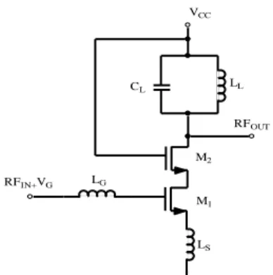
The architecture considered for modeling is described in Figure 4. It consists of a 2.45GHz OOK transmitter and the associated receiver.
FIGURE 4:TRANSMITTER ARCHITECTURE
The transmitter gathers of a 2.45GHz oscillator generating a sine voltage which is amplified to the maximal allowed power in the ISM band and PWM. The modulating signal’s duty cycle is determined according to the amplitude of the audio signal. The ramp block receives a rising edge from the
39
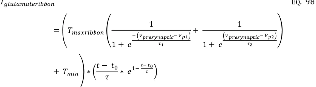
sampling reference clock which is approximately one thousand times higher than the sampling frequency of the microphone allowing to reach a maximal theoretical resolution of 10 bits at 20kHz [24]. The determination of the maximum number of bits reached by the PWM are one of the goals of the modeling and are discussed in the Section I.C.6 and II.D. The shape of the signals of relevance are given in Figure 5.
An example of ideal simulation, without noise nor distortion is given in Figure 5, where the different voltages represented are plotted as a function of time. In the top window, the output voltages of the low frequency amplifier (sine), ramp (triangle) and comparator (rectangle) are superimposed. In the bottom window, the RF signal (2.45 GHz carrier modulated with a PWM signal) is presented.
FIGURE 5:TRANSIENT IDEAL SIMULINK® SIMULATION.TOP : AMPLIFIER, RAMP AND COMPARATOR OUTPUT,BOTTOM :RF SIGNAL.
C.
Model implementation
1.
Baseband module implementation
The implementation in Matlab/Simulink® (displayed in Figure 6) was graphically very close to the electrical architecture, allowing a fine tuning of each block. In this way, corruption of these blocks with non linearities or noise perturbations was made easier as well as new implementation in case of architecture redesign.
40
FIGURE 6:BASEBAND MODULE DESCRIPTION IN SIMULINK® ENVIRONMENT (THE BLOCKS WERE CREATED USING MATLAB® CODE)
For the first system simulation, the number of bits associated with the PWM encoding (NPWM) has to be defined. The PWM upper limit depends on the product of the microphone frequency and the PWM Least Significant Bit (LSB) which should be enclosed in the ISM frequency range of the selected ISM band [2.4GHz;2.5GHz]. The maximum baseband frequency should be lesser than two times the selected ISM frequency range to respect the Shannon theorem [36, 37], which established the upper limit of NPWM. 𝑓𝑚𝑖𝑐𝑟𝑜𝑝ℎ𝑜𝑛𝑒∗ (2(𝑁𝑃𝑊𝑀 +1)) < (50) ∗ 106 2 ⇒ 𝑒𝑥𝑝((𝑁𝑃𝑊𝑀+1)∗𝑙𝑛2) < 50 ∗ 10 6 𝑓𝑚𝑖𝑐𝑟𝑜𝑝ℎ𝑜𝑛𝑒 ⇒ 𝑁𝑃𝑊𝑀 < (𝑙𝑛 ( 50∗106 𝑓𝑚𝑖𝑐𝑟𝑜𝑝ℎ𝑜𝑛𝑒)) 𝑙𝑛(2) − 1 ⇒ 𝑁𝑃𝑊𝑀 ≤ 10 EQ. 1
41
where fmicrophone is the maximal microphone frequency and was equal to 20kHz for the microphone used.Furthermore to permit efficient filtering, the PWM signal frequency band, defined by the Least Significant Bit (LSB) should be significantly lower than the selected ISM band frequency range. Therefore the NPWM value selected for subsequent testing was 8 bits (further refined in Section II.C and II.D)
2.
Cyclic Ratio block and Oscillators description
a)
Voltage Controlled Oscillators (VCO)
Jitter and phase noise limitations are of particular importance in this architecture since a high jitter on the low frequency oscillator irremediably causes demodulated signal distortion and high phase noise on the local oscillator results in spectral leakage outside the allowed frequency band.
In this Section, we did not study the influence of phase noise, resulting in a unsophisticated modeling of the oscillators. The study of oscillator perturbations on the signal integrity were studied in Section II.E, in terms of phase noise characteristics to determine statistical parameters for time domain simulation. Mathematical models were developed in Section II.E, to study jitter influence on the signal integrity. These models were mainly statistical, discarding their use in temporal simulations since the temporal simulation may characterize statistical effects only if repeated a significant number of times, which obviously would lead to a significant increase in simulation time. In this case, temporal models for oscillators included in the transmitter models brought no significant advantages than considering jitter inclusion independently of the other blocks.
The proposed architecture is composed by an initial PWM followed by an OOK modulation thus two oscillators working at different frequencies were required. The low frequency oscillator with a central frequency of 20kHz associated to the PWM ramp generator was critical for the system accuracy and the high frequency oscillator working with a central frequency of 2.45GHz had to be confined in the 2.4 – 2.5 GHz ISM band.
Furthermore anticipating eq. 30, presented in Section II.G.1 (which indicates that phase noise is inversely proportional to the consumed power and this characteristic is of interest for further optimization of the transmitter),the power budgeting of each block set a maximal phase noise value and thus a maximal carrier frequency shift within the ISM band (cf Section II.E).
42
b)
Cyclic Ratio generation block
The cyclic ratio module has two clock generators as inputs:
The first clock generator (clk1) has a frequency of 20kHz which corresponds to the sampling frequency of the signal coming from the microphone. 20kHz is therefore the maximum frequency allowed between two consecutive frames.
The second clock generator (clk2) has a frequency of 20000 ∗ (2(NPWM + 1)) where NPWM is the maximum number of bits that will compose the PWM signal. As discussed above, NPWM is fixed to 8. This clock generator should not be confused with the carrier oscillator (fosc) used for the OOK modulation
The cyclic ratio generator creates a clock signal having a frequency of 20 kHz and with a clock ratio of2(N+1)1 . The cyclic ratio algorithm is summarized by the flowchart exhibited in Figure 7.
FIGURE 7: FLOWCHART OF THE ALGORITHMS USED FOR THE CYCLIC RATIO CREATION (LEFT) AND FLOWCHART OF THE RAISING EDGE DETECTOR (RIGHT)
43
where ycyclicratio is the output of the cyclic ratio block. Remembering that clk1 is the variable associated with the first oscillator(having a frequency of 20kHz) and clk2 is a variable associated with the second oscillator(with a frequency of 20000 ∗ 2(8)), clk_1 is the previous state associated with the local variable clk in the raising edge detection
For the cyclic ratio generator algorithm, first the reading of persistent variables and then the update of local variables is made in order to load variable contents between two program executions (clk1, clk2).Then one raising edge detector linked to the faster clock clk2and also a second raising edge detector which identified the raising edge of the second clock signal clk1, were employed. The principle of this algorithm is straightforward: an output signal of time length equal to
1
20000∗2(8) is created each time the two raising edge detectors are equal to 1.
The raising edge detection was performed using a simplistic algorithm which used a buffer to store the value of an external clock (clk). The current value of clk and the previous state value (clk_1) were compared (the output raised to 1 when clk=1 and clk_1=0).
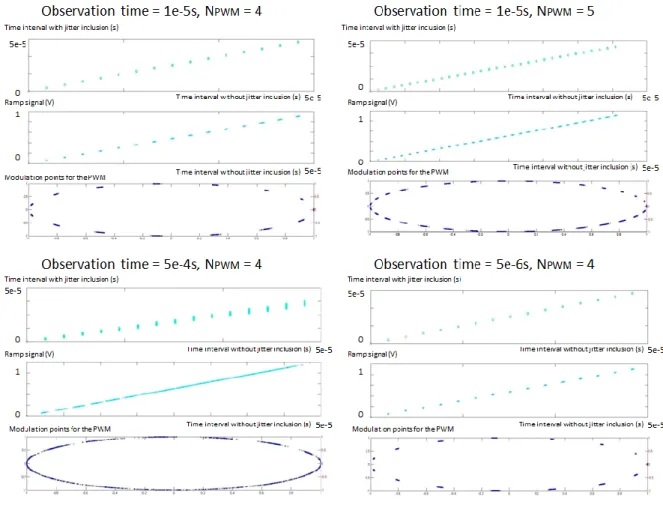
The time variations of clk1, clk2 and the created ramp reset signal (also named local oscillator) are indicated in Figure 8.
FIGURE 8:LOW FREQUENCY (LOCAL) OSCILLATOR PULSE CREATION BY THE CYCLIC RATIO BLOCK USING TWO OTHER OSCILLATORS
3.
Power Amplifier
The mathematical model ofthe Power Amplifier (PA) can be found in [38, 39] and is usually described by eq. 2:
44
𝑣𝑠(𝑡) = 𝑎1𝑣𝑒(𝑡) + 𝑎2𝑣𝑒2+ 𝑎3𝑣𝑒3 EQ. 2
where ve(t) is the input voltage, vs(t) the output voltage, and a1, a2, a3 scalar coefficients which depend on the 1 dB compression point (P1DB) and the Intermodulation Products of the second and third order (IIP2, IIP3) as described in [40-43]. The corresponding powers are then derived from eq. 2 according to the circuit input and output impedances. The PA mathematical model was limited to the third order time description but can be further extended as expressed in [44, 45] if needed.
However as the a3 coefficient is negative to account for saturation effects, using only eq. 2 would lead to a vs decrease if ve was higher than a specific value vmax. Consequently, in the PA model construction, the local maximum of eq. 2 is used to switch equations for vs description (cf eq. 3).
𝑣𝑠(𝑡) = {𝑎1𝑣𝑒(𝑡) + 𝑎2𝑣𝑒(𝑡) 2+ 𝑎
3𝑣𝑒(𝑡)3 𝑖𝑓 𝑣𝑒 ≤ 𝑣𝑚𝑎𝑥
𝑣𝑠(𝑡) + 𝑎1 𝑣𝑒(𝑡) 𝑖𝑓 𝑣𝑒> 𝑣𝑚𝑎𝑥
EQ. 3
The time where ve=vmax is reached (tp) can easily be computed from the previous equation. The transfer expression for ve>vmax has to be modeled in order to correctly simulate input signals in the saturation region of the PA.
The modeled characteristic is compared to actual SPICE simulation in Figure 9.
FIGURE 9:COMPARISON BETWEEN THE POWER GAIN CURVES FROM MATHEMATICAL MODELING AND SPICE SIMULATIONS
The PA model also includes noise corruption. The added PA noise (Na) was supposed to be white noise because 1/f noise can be neglected around the working frequency (2.45GHz). The added noise is described by the Noise Factor (F), given by eq. 4:
45
𝐹 = 𝑁𝑎+ 𝐺𝑁𝑖 𝐺𝑁𝑖
EQ. 4
where Na is the PA added noise,G the power gain and Ni the input noise. Na and Ni were obtained using a SPICE Periodic Noise analysis on the PA only or on the PWM output block respectively. Only the output noise was take into account. G was obtained by a Periodic Steady State (PSS) analysis in Cadence. Other analysis may be used to extract those parameters (Scattering Parameters (SP) analysis for power gain, direct noise analysis for output noises floor,...)
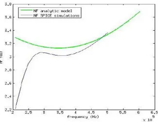
FIGURE 10:COMPARISONS BETWEEN THE MATHEMATICAL NF MODELING SIMULATIONS AND SPICE NF SIMULATION OF THE PA
Figure 10 presents the comparison between the Noise Figure (NF) from analytical model and electrical simulations. The NF simulated shape was not perfectly following the SPICE simulated NF since the equations implemented for NF modelling were standard equations to ease the computations, however the difference was very small (less than 1dB) between the NF values. Furthermore this parameter is not of critical importance because the PA is placed at the end of the transmitter and, according to Friss Formula [46].
Figure 11 shows the block diagram of the PA model. For modelling purpose, two PA were associated, one modelling the ON state of the PA and the other the OFF state. In this model the gain KpOFF of the OFF state was set to zero to decrease the simulation time. However this approximation is inexact as the real measurements made on the CMOS prototype (cf Section I.C.6) showed that during the OFF state of the PWM a few signal flowed from the PA input to the output at the working frequency due to parasitic capacitance.
46
The 2.45 GHz Voltage Controlled Oscillator (VCO) signal was applied to the respective PA inputs. The PA outputs were controlled by PWM and 𝑃𝑊𝑀̅̅̅̅̅̅̅. Finally white noise corruption (Na) was added in the PA model.
FIGURE 11:BLOCK DIAGRAM OF THE PA MODEL WITH NOISE CORRUPTION
The errors between the SPICE simulations and the mathematical models may arise from the low power design which causes huge non linearities, just partly taken into account in this modelling work, to reduce simulation time.
4.
Ramp creation
The PWM signal was obtained using a ramp block generator which was compared to the input signal (wave sound from the microphone). A pulse is generated at a frequency of 20kHz and resets the ramp. Shorter is this pulse time length, greater is the accuracy that can be reached by the PWM.
The entire ramp can be constructed adding both the raising and the falling part equation selected by associated window functions (eq. 5)
𝑠(𝑡) = 𝑠1(𝑡) ∏ (𝑡) + 𝑠2∏ (𝑡)
𝑓𝑎𝑙𝑙𝑖𝑛𝑔 𝑟𝑎𝑖𝑠𝑖𝑛𝑔
EQ. 5
where Πraising is a window function equal to 1 only when the ramp is raising and Πfalling the opposite window function; s1 and s2 are obtained using polynomial extraction functions of the raising region of the ramp and the falling region of the ramp respectively.
![FIGURE 1: EAR ANATOMY AND COCHLEAR IMPLANT (ATTRIBUTED TO [5])](https://thumb-eu.123doks.com/thumbv2/123doknet/13058692.383500/26.918.238.733.633.938/figure-ear-anatomy-cochlear-implant-attributed.webp)
![FIGURE 36 : JITTER MEASUREMENT IN A TIME INTERVAL (THIS FIGURE IS REDRAWN FROM [111])](https://thumb-eu.123doks.com/thumbv2/123doknet/13058692.383500/98.918.160.726.425.772/figure-jitter-measurement-time-interval-figure-redrawn.webp)
![Figure 73displays the mean activation time and mean inactivation time of Na v which depend on the cell membrane voltage (redrawn from [220])](https://thumb-eu.123doks.com/thumbv2/123doknet/13058692.383500/163.918.249.617.611.834/figure-displays-activation-inactivation-depend-membrane-voltage-redrawn.webp)
![Figure 85 shows the neuronal noises we simulated. The inclusion of these noises to the simulated spike train is displayed in Figure 86, which is comparable to experimental auditory nerve fibers spike trains fulfilled in [315-321]](https://thumb-eu.123doks.com/thumbv2/123doknet/13058692.383500/187.918.117.758.740.1053/neuronal-simulated-inclusion-simulated-displayed-comparable-experimental-fulfilled.webp)
