HAL Id: cea-01841693
https://hal-cea.archives-ouvertes.fr/cea-01841693
Submitted on 15 Jan 2019
HAL is a multi-disciplinary open access
archive for the deposit and dissemination of
sci-entific research documents, whether they are
pub-lished or not. The documents may come from
teaching and research institutions in France or
abroad, or from public or private research centers.
L’archive ouverte pluridisciplinaire HAL, est
destinée au dépôt et à la diffusion de documents
scientifiques de niveau recherche, publiés ou non,
émanant des établissements d’enseignement et de
recherche français ou étrangers, des laboratoires
publics ou privés.
Automated vision-based system for parallel contactless
micromanipulation
E. Vela, M. Hafez, Stéphane Régnier
To cite this version:
E. Vela, M. Hafez, Stéphane Régnier. Automated vision-based system for parallel contactless
microma-nipulation. 2013 16th International Conference on Advanced Robotics (ICAR), Nov 2013, Montevideo,
Uruguay. �10.1109/ICAR.2013.6766530�. �cea-01841693�
Automated Vision-Based System for Parallel
Contactless Micromanipulation
Emir Vela
∗, Moustapha Hafez
†and St´ephane R´egnier
‡∗Universidad de Ingenier´ıa y Tecnolog´ıa Av. Cascanueces 2221 Santa Anita, Lima, Peru
Email: evela@utec.edu.pe
†CEA LIST, 18 route du Panorama, BP 6, Fontenay-aux-Roses, France Email: moustapha.hafez@cea.fr
‡Institut des Syst`emes Intelligents et de Robotique
Universit´e Pierre et Marie Curie, CNRS UMR 7222, 4 Place Jussieu, 75005 Paris, France Email: stephane.regnier@upmc.fr
Abstract—This paper presents the automated parallel non-contact manipulation of glass beads ranging from 30 up to 300 µm in size under water. Non-contact micromanipulation is performed by generating controllable laser-induced thermocapillary flows that are capable of dragging the beads. Automated manipulation process is achieved with visual servoing in order to accurately manipulate the beads in a parallel and high-speed manner. Image correlation allowed to detect the bead positions and to provide these positions to a mirror scanner that addressed the IR laser beam at a certain position from the bead. By scanning the laser beam from one bead to another, automated parallel manipulation of beads at speeds in the range of mm·s−1 was demonstrated.
I. INTRODUCTION
The growing miniaturization, development and production of microsystems in both the industrial and research field require versatile and autonomous micromanipulation systems of microcomponents. The diversification, in consequence com-plexity, of these systems such as MEMS, MOEMS, bioMEMS, hybrid electronic devices, needs the use of several microfabri-cation processes in order to engineer microcomponents made of different geometries, materials and physical properties. These components have to be assemble into microsystems for broad applications. Due to the potential market of micro and nano devices, industries need to improve their throughput. Indeed, the micromanipulation and assembly of microcompo-nents rely on operators thus limiting large production. How-ever, autonomous micromanipulation and assembly systems could achieve cost-effective devices with high throughput. This field is rapidly progressing as autonomous systems are of great interest to massively parallel manipulate and assemble microscale parts. Several research groups are working on micromanipulation methods. Most works are based on mechan-ical or contact micromanipulation modes [1], [2], [3]. However, contact micromanipulation does not allow parallel manipula-tion capabilities at high-speed due to the limited displacement speed of microtools (tens of microns per second). Non-contact micromanipulation are more suitable for parallel manipulation. Among non-contact methods such as magnetic fields [4], [5], dielectrophoresis [6], [7], electroosmosis [8], electrowetting [9], acoustic waves [10], [11], thermocapillary flows [12], [13], [14], optical tweezers have achieved a more advance level of automation [15], [16]. Nevertheless, it is limited to
objects up to tens of microns in size, transparent spherical objects and it reaches about tens of picoNewtons in forces. In this work a fully automated non-contact manipulation system capable of dealing with the challenges mentioned above is presented. The non-contact method used was the generation of highly localized microflows in a thin water layer using an infrared (IR) laser beam. The focused IR laser irradiated from below the liquid water layer thus producing a localized heat source by laser absorption. As a consequence, the established heat gradient at the liquid free surface generated unbalanced surface stresses. These stresses caused convection flows in order to reach an energetic equilibrium in the liquid medium, the Marangoni effect.
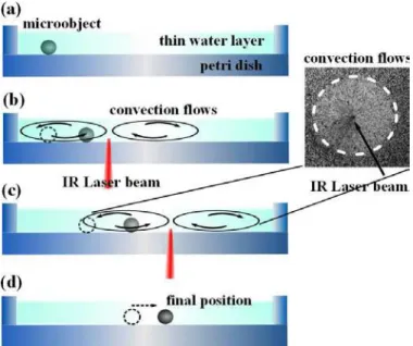
Fig. 1. Manipulation method using the Marangoni effect. (a) static microob-ject within a thin water layer, (b) IR laser beam is shot thus generating convection flows and microobject is dragged, (c) laser beam is shot into another position so that microobject follows it (inset shows a picture of the convection flows around the laser beam), (d) laser beam is turned off in order to place the microobject in a final position.
The flows are toroidal shaped around the heat source. A significant advantage of this method is that microobjects can be dragged by the flows regardless of their shape, material
NI Card
scanner electronic board
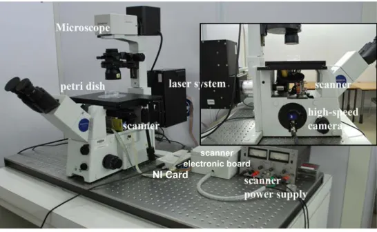
Fig. 2. Experimental setup is composed by a commercial inverted microscope, a high-speed monochrome camera, a laser shot system, a mirror scanner, a NI card, electronic boards and a computer. The IR laser beam is directed by the mirror scanner through the microscope objective towards the sample, where microobjects are to be manipulated. The inset shows the mirror scanner integrated under the nosepiece and the high-speed camera located at the left port of the microscope.
composition and range size. While the IR laser beam is irradiating the liquid, the objects, inside the convection flows, move towards the laser beam. When the IR laser beam is switched off, the heat gradient disappears and therefore the convection flows become null (Fig. 1). As a result microobjets stop moving [17].
To accurately manipulate the microobjects using this method, it was necessary to automate the manipulation process. A visual servoing system was implemented with a high-speed camera that provided the images containing the objects while moving. Then using image processing methods the objects positions were obtained in order to be used as positions feedback in the implemented controller algorithm. Thus the IR laser shot was controlled regarding the positions of the microobjects. Furthermore, a strategy to accurately manipulate two glass beads in a parallel manner and at speeds in the range of mm·s−1 was demonstrated.
The scenarios of interests are the manipulations of hybrid microscale parts for self-assembly for high-throughput mi-crosystems production, or even the contactless manipulations of biological cells by only using liquid flows that could help to investigate in cells behaviors.
II. EXPERIMENTAL SETUP
The experimental setup consists of an inverted microscope (Olympus IX71) with a 4× objective (numerical aperture NA= 0.1; working distance = 18.5 mm) and an 1.6 magnification lens giving a total magnification of 6.4, it allowed to have a visible workspace of about 5×5 mm2
. The manipulated objects were as large as 0.3 mm in size. An IR laser beam of 1480 nm wavelength, 120 mW of maximum power and a collimated radius of 3 mm was used, it was provided by OCTAX Microscience GmbH. The laser shot system was mounted at the microscope rear port. The IR laser has an
absorption coefficient in liquid water of 23.45 cm−1. Distilled
water was used as the liquid medium. The filling depth was up to 0.6 mm for most experiments while maintaining a free surface, water-air interface. As a container, a petri dish made of soda-lime-glass with 60 mm in diameter and 12 mm in height was used. Considering all the optical components that the laser beam past through, including the petri dish, a 80 mW of power was measured at the output (120 mW of input power). This output power is used to irradiate the liquid layer, according to the Beer-Lambert law and taking 0.6 mm of water depth, a power of 3.13 mW is obtained at the liquid-air interface. As a result, about 96% of the laser power is absorbed by the water layer.
In order to monitor the sample and movement of the mi-croobjects, a high-speed DALSA Genie Monochrome CMOS camera with 1 inch CMOS sensor and 1400×1024 pixels at a frequency acquisition rate of 60 fps was installed in the left port of the microscope. This camera allowed to take pictures by varying the image pixels and frame rate. Additionally, a C-mount Olympus lens adapter of 0.33× magnification was coupled to the camera in order to enlarge the field of view displayed on the computer screen. Fig. 2 illustrates the experi-mental setup, where a dichroic mirror (from Octax GmbH) was installed under the microscope nosepiece. This reflected the IR laser beam into the entrance pupil of the microscope objective in order to be focused into the sample. Furthermore, the mirror was mounted on a 2 degree of freedom electromagnetic actuator to move the mirror and in consequence to direct the laser beam at any x-y position of the sample workspace. A NI USB-6210 DAQ card was used to drive the mirror scanner and the laser beam shot.
A. Two DOF Tip-Tilt Mirror Scanner
As the setup is based on a commercial microscope, all components of the system were designed or chosen in order to
F
F
coil
permanent
magnet
(a)
(b)
(c)
IR laser beam
dichroic
mirror
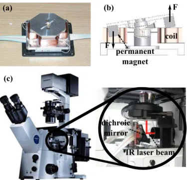
Fig. 3. Two DOF mirror scanner. (a) 2-DOF TIP/TILT electromagnetic device, (b) Forces exerted by a couple of electromagnets, (c) Mirror scanner mounted on a commercial inverted microscope, the IR laser beam is directed by the controllable dichroic mirror at any planar position in the sample.
be mounted on it. A 2-DOF mirror scanner was needed in order to direct the laser beam at the sample workspace and control it. Due to compactness, a custom-made TIP/TILT mirror scanner (Fig. 3(a)) was preferred to galvanometric mirrors [18], [19]. This device was developed by the CEA-LIST. IIt is a compact mechatronic device actuated by four electromagnets in a push-pull antagonistic configuration. The forces exerted by the actuators are illustrated in Fig. 3(a. The magnitudes of these forces are identical for each magnet. They are placed on four cardinal positions around the pivot of the mirror holder. Hence a couple of electromagnets gives 1 rotational degree of freedom. Due to its dimensions (50×50×15 mm3
) this device can be easily mounted on an inverted microscope, under the nosepiece as shown in Fig. 3(c). A dichroic mirror is mounted on this device, at a 45◦ position, in order to reflect the IR
laser beam into the objective. In this configuration, the dichroic mirror makes a 45◦angle with the incident laser beam and the
microscope optical axis. It allowed to direct the laser beam at the sample without interfering with the imaging light directed towards the high-speed camera, thus reducing considerably the laser beam optical path and distortions.
III. AUTOMATION
A. System Calibration
The micromanipulation system had to be calibrated, due to geometrical distortions introduced by the mirror scanner and optical components, in order to have an accurate and precise control of the microobjects positions and manipulation. The IR laser beam, directed by the TIP/TILT mirror scanner into the sample, was not projected exactly on the desired position in the sample. For instance, if a square position reference was given to the scanner controller, in the sample the expected projected square trajectory of the laser beam was a curved
0 100 200 300 400 500 0 100 200 300 400 500
x image frame [pixels]
y image frame [pixels]
desired ref. corrected ref.
(a)
(b)
500 x 500 pixels frame IR laser positions
Fig. 4. Calibration of the mirror scanner. (a) Laser positions are obtained from the workspace by image segmentation of the captured image, (b) Laser positions in a linear trajectory obtained with a curve command positions given to the mirror scanner. Image frame of 500 × 500 pixels.
trajectory. These distortions are explained in [20]. To correct the distortions, a third degree polynomial approximation was used as follows: xc= axx+bxy+cxx 2 +dxxy+exy 2 +fxx 2 y+gxx 3 +hxy 2 x, (1) yc= ayx+byy+cyx 2 +dyxy+eyy 2 +fyx 2 y+gyx 3 +hyy 2 x, (2) where xc and yc are the corrected positions to be sent to the
scanner controller after calculation of eq. (1) and (2), x and y are the needed positions of the laser beam in the sample. To calculate the coefficients of this equation system, at least eight positions values of x and y are needed to obtain an equation system of eight equations and eight unknowns respectively . The indexes 1 up to 8 represent the eight measured laser positions in the sample as follows:
x1c .. . x8c | {z } X = x1 y1 x 2 1 · · · x 3 1 y 2 1x1 .. . ... x8 y8 x28 · · · y 3 1 y 2 8x8 | {z } P × ax .. . hx | {z } C , (3) where X is the corrected position vector, P is the matrix containing the terms of the polynomial and C is the coefficient vector of the polynomial, this gives X = P C. In order to solve this system, that means to find the coefficient vector, a reference position set of eight values was used for X. The val-ues of P were calculated with eight measured laser positions (Fig. 4(a)). The eight laser positions (x, y) in the sample were captured by a camera and calculated by image segmentation. In other words, the mirror scanner was commanded by eight X values that directed the laser beam at eight positions in the sample, then the eight laser positions (x, y) were measured in order to compute the matrix P , finally the coefficients C were calculated according to C = P−1X. The same process
was performed for Y vector. Once C obtained, the polynomial equations system (Eq. (1) and (2)) for X and Y was introduced in the scanner controller. For instance, Fig. 4(b) shows the desired linear trajectory positions of the laser beam in the sample (square marks), these are introduced to Eq. (1) and (2) in order to compute the command positions to be given to the mirror scanner (circle marks). As the scanner was commanded with voltage and the measured positions in the sample were in pixels, a linear correspondence was calculated in order to convert pixels to volts.
B. Image Processing
In the calibration process image segmentation was per-formed to obtain the laser positions from the sample. For the visual servoing of the automated micromanipulation system, an image correlation method was preferred because it is robust, fast and accurate for small regions of interests (ROIs). Fig. 5 shows the image correlation used to automate the manipulation process with position feedback. In order to track an object, a template of this (inset: top right of the figure) is first captured. The template is then correlated with the image ROI to calculate the correlation coefficients (Fig. 5(b)). The position of the maximum coefficient gives the position of the object, the brightest dot in the image. The image processing methods were performed using the OpenCV library.
(a)
(b)
microbead
template
Fig. 5. Image correlation method used to track microobjects. (a) A template of a microbead is correlated to an image ROI of the workspace containing the object, inset: template of the microobject, (b) A map of the position of the correlation coefficients, the brightest dot corresponds to the microbead position.
C. Control Algorithm
The automation of the micromanipulation system was possible due to the predictable behavior of the convection flows and negligible inertial effects at this scale length. The control algorithm was developed in order to automatically manipulate microbeads in a parallel manner and at high speed. For instance, the handling of two glass spherical beads ranging from 30 to 90 µm in diameter are reported. In addition, with the algorithm presented below, spherical beads up to 300 µm can be automatically manipulated. This algorithm was developed based on a visual servoing in which the beads are tracked while moving until they reaches their target position. The control algorithm was as follows (Fig. 6):
1) Initialization: Detection of the glass beads using im-age segmentation within an imim-age frame of 500×500 pixels in size.
2) Image templates of the beads are captured and regions of interest (ROI) are located at the beads centre of mass.
3) Reference target positions are introduced by an user with a computer mouse or written in the program graphical unit interface (GUI).
4) Closed-loop starts: Image correlation starts to track the beads and give the calculated positions to the mirror scanner controller.
5) A vector path is computed between the bead and target positions.
6) The laser beam is directed by the scanner at a distance d from the bead. The laser is shot during an exposure time te The laser position shot is located on the
computed vector path.
7) The ROI position is updated to the current bead position.
8) The bead is positioned at the target position, the mirror scanner is turned off and the manipulation process ends.
The beads were tracked in order to compute their position during the whole process. Their positions provided to the system the feedback position required to compute the location where the laser had to be shot until the beads reached their target position. The image correlation time depended on the size of the ROI. A size of 100×100 pixels was used and the time to find a bead position (size of a bead was about 10 up to 20 pixels in diameter) within the ROI was about 2 ms. After detection of the beads by segmentation, the templates were captured and the ROIs were positioned at the center of mass of the beads. Once the correlation was performed in the whole ROIs, the bead position were obtained. A vector path was then calculated between the bead and target positions. The laser is shot a distance d from the bead. The bead was dragged by the laser shot. The image correlation was performed in order to compute the new bead position. Once the bead position computed, the ROI updated its location in order to have the new bead position at the centre of the ROI. For a new bead position, vector path was recalculated. The calculation of the bead position is permanently tested, if the bead moves too fast and goes out of the image ROI, the process restarts in order to detect the current bead location. For each iteration, the distance between the bead and the target positions was compared to a tolerance distance introduced in the program. When the bead-target distance was smaller than a tolerance distance, the process ended. The tolerance gave the accuracy of manipulation. The highest accuracy that the system can achieve was one pixel, which is the position error given by the image correlation process. In the micromanipulation system, one pixel corresponded to 5 µm. The time to achieve the displacement of a bead in a closed loop was given by the addition of the laser exposure time (50-90 ms) and the scanner response time (125 ms) that gave 215 ms. The correlation time (2 ms) was not taken into account because the image correlation was performed in a parallel thread.
calculation of the bead and laser
position calculation of the ROI position calculation of the bead position -correlation bead laser target
Fig. 6. Schematic of the tracking method using image correlation. The laser is shot in order to the bead be dragged, the bead moves and the ROI updates its location at the new bead position. Once the bead position is computed, the laser is shot again.
The automated manipulation process was implemented using the C++ language in a windows operating system. A multithreaded program was necessary to perform the tracking process, the IR laser shot with a determined exposure time and the GUI display in three threads respectively. A serial programming manner blocked these processes while one of them is being performed. For this purpose, the OpenMP application programming interface (API) was used. Fig. 7 shows the threads used in the program. Thread 1: Image acquisition and GUI display; thread 2: image processing; and thread3: DAQ NICard and control of the laser scanner and IR laser shot. These threads communicate each other through shared variables, two for the image acquisition and processing and two for the positions calculations.
Master thread Image acquisition & GUI display Image processing correlation method Laser-scanner & IR laser NIcard Close program shared variables shared variables I I P P 1 1 0 0
Fig. 7. Block diagram of the implemented multithreaded program. The main thread is divided into three independent threads which communicates between each other through shared and protected variables. I0,1and P0,1are the image
and position shared variables.
IV. EXPERIMENTAL RESULTS
The automated non-contact manipulation of two beads in parallel manner is depicted in Fig. 8. The glass beads were 50 and 85 µm in diameter respectively. The water depth was 450 µm. Firstly, the beads were located by the user in an image frame of 500 × 500 pixels (Fig. 8(a)). One pixel corresponded to 5 µm in the sample workspace. Then the detection process was activated on the GUI by the user. A detection filter was implemented to avoid the detection of particles or beads smaller than 30 µm and larger than 150 µm in diameter. These parameters can be changed in the program. Once the beads were detected, the user introduced the target positions or destinations by clicking with a computer mouse on the displayed video (Fig. 8(b)). The target positions were shown by a black circle of 50 µm in radius. This dimension also represented the positioning tolerance. That means when the beads centre of mass was located at a distance smaller the 50 µm from the target position, the automated manipu-lation process ended. This tolerance could be changed in the program. The highest accuracy measured was of 5 pixels (25 microns) with the implemented algorithm controller. However an accuracy of 1 pixel could be achieved with a more suitable controller. After the introduction of the target positions, the laser was shot at a distance of 450 µm from each bead and during 90 ms of exposure time (Fig. 8(c)). These parameters are according to [21] in order to drag the beads at a speed in the range of mm·s−1. The laser position was switched from
one bead to the other thus each bead was dragged one after the other (Fig. 8(c-h)). This strategy was implemented because of the radial shape of flows. Due to the different distance destinations, one of the two beads arrived at its target position faster (Fig. 8(g)). As a result, the laser shot focused on the remaining bead until it arrived at its destination. When the two beads were positioned in their respective target positions, the automated process stopped. Pictures in Fig. 8(b-h) are shown at an interval of 1 s, taking a time of 6 s since the user introduced the target positions until the beads arrived at their respective final positions. The trajectory of the beads were not straight, this was due to the radial shape of flows, however the algorithm controller achieved to position the beads at their destinations because the linear trajectories were computed at every position of the beads.
(a)
(b)
(g)
(h)
glass beads final positions 200 micronsFig. 8. Image sequence depicting the automated manipulation of two glass beads. (a) The bead positions are detected by the program using image segmentation. (b) The user introduces the respective target positions with a computer mouse by clicking on the image frame. (c-h) The IR laser is shot by switching its position from one bead to the other until the beads arrive at destination. The pictures are shown at intervals of 1 s. Scale bar of 200 µm.
V. CONCLUSION AND PERSPECTIVE
A. Conclusion
In order to contacless manipulate microobjects in a parallel and at high speed manner, an automated non-contact micro-manipulation system is presented. This system is capable of manipulating objects regardless of the material composition and in addition within a large range size from 30 up to 300 µm. The automated manipulation of two glass beads was achieved and reported. A single 2-DOF mirror scanner allowed to adressed an IR laser at a specific position in the sample. A visual servoing was implemented to compute the bead position while moving and send the position to
the controller, thus the mirror scanner and laser shot were controlled. This was based on an image correlation method. It was demonstrated that convection microflows can be used to automatically manipulate objects under water without the need of mechanical grippers or tweezers. This is of great interest for the fabrication of hybrid microdevices, self-assembly or production with batch processes at the microscale for high throughput. With a faster mirror scanner and a more suitable algorithm controller the manipulation time could be improved. Moreover the induced microflows could be reconfigurable according to the required manipulation, for example flows can be engineered by changing the pattern of the laser beam irradiation such as circles, lines, multiple dots or other specific geometry, and in an automated manner.
B. Perspective
The automation of this method was implemented by a simple position feedback, in which the distance between the bead and goal position was computed in order to be compared to the tolerance position. A more suitable regulator could be implemented to improve the performances of the system, it could increase the speed and accuracy of the automated process. For instance, in the program the distance at which the laser was shot was not variable as well as the exposure time. If this parameters could be changed with respect to the computed distance between a bead and its destination, the bead could be moved faster when it is far from the goal position and slower when it is close to target position. Hence, a position accuracy of 1 pixel can be reached in a shorter time as 1 pixel is the error due to the image correlation. The main drawback of this method for a multiple bead manipulation is the toroidal shape of the engendered microflows, this is due to the radial symmetry of convection flows with respect to the heat source. The implemented control algorithm did not take into account this effect. A more suitable manipulation strategy could be implemented with a sophisticated regulator. Apart from the control algorithm, a faster mirror scanner could be used so that the laser could switch from one bead to another much faster or to generate dedicated patterns faster in order to manipulate the objects at higher speeds according to [21]. Future work will deal with the mentioned problems mentioned above, study of a better control and image processing algorithms for multiple beads and non-spherical micro-objects manipulation in an autonomous manner. Furthermore, it would be very interesting in using this method to manipulate biological cells such as ovocytes [22]. This could be possible because cells are spherical and flows are capable to drag them.
ACKNOWLEDGMENT
This work was supported by the European GOLEM project, Bio-inspired Assembly Process for Mesoscale Products and Systems, FP 6, NMP, contract No. STRP 033211. The authors acknowledge OCTAX Microscience GmbH for providing the laser shot system.
REFERENCES
[1] M. Sitti, and H. Hashimoto, 2000. “Two-Dimensional Fine Particle Positioning Under Optical Microscope Using a Piezoresistive Cantilever as a Manipulator,” Journal of Micromechatronics, 2000, vol. 1(1), pp. 25–48.
[2] F. Dionnet, S. R´egnier, and J.C. Guinot, “Vision and Force Based Autonomous Micromanipulation,” in Proceedings of IEEE International
Conference on Robotics and Automation, May 2004, vol. 5, pp. 5019-5024.
[3] M. Probst, C. Hurzeler, R. Borer, and B. Nelson, “A Microassembly System for the Flexible Assembly of Hybrid Robotic MEMS Devices,”
International Journal of Optomechatronics, 2009, vol. 3(2), pp. 69-90. [4] H. Lee, A. M. Purdon, and R. M. Westervelt, “Manipulation of biological
cells using a microelectromagnet matrix,” Applied Physics Letters, 2004, vol. 85(6), pp. 1063-1065.
[5] E. P. Furlani, “Magnetophoretic separation of blood cells at the mi-croscale,” Journal of Physics D: Applied Physics, 2007, vol. 40(5), 1313. [6] Z. Abidin, and G. H. Markx, “High-gradient electric field system for the dielectrophoretic separation of cells,” Journal of Electrostatics, 2005, vol. 63, pp. 823-830.
[7] A. Rosenthal, and J. Voldman, “Dielectrophoresis Traps for Single-Particles Patterning,” Biophysical Journal, 2005, vol. 88.
[8] G. Hwang, R. Braive, A. Cavanna, A. Ouerghi, I. Robert-Philip, A. Bev-eratos, S. Haliyo, I. Sagnes, and S. R´egnier, “Electro-osmotic Propulsion of Helical Nanobelt Swimmers,” The International Journal of Robotics Research, 2011, vol. 30(7), pp. 806–819.
[9] H. Ren, R. B. Fair, M. G. Pollack, and E. J. Shaughnessy, “Dynamics of electro-wetting droplet transport,” Sensors and Actuators B: Chemical, 2002, vol. 87(1), pp. 201-206.
[10] J. Shi, D. Ahmed, X. Mao, S. Lin, A. Lawit, and T. Huang, “Acoustic tweezers: patterning cells and microparticles using standing surface acoustic waves (SSAW),” Lab on a Chip, 2009, vol. 9, pp. 2890-2895. [11] O. Manneberg, B. Vanherberghen, B. Onfelt, and M. Wiklund,
“Flow-free transport of cells in microchannels by frequency-modulated ultra-sound,” Lab on a Chip, 2009, vol. 9(6), pp. 833-837.
[12] A. Basu, and Y. B. Gianchandani, “Virtual microfluidic traps, filters, channels and pumps using Marangoni flows,” Journal of Micromechanics
and Microengineering, 2008, 18(11), 115031.1-115031.11.
[13] M. R. de Saint Vincent, R. Wunenburger, and J.-P. Delville, “Laser switching and sorting for high speed digital microfluidics,” Applied
Physics Letters, 2008, vol. 92(15), pp. 154105(3).
[14] W. Hu, K. S. Ishii, and A. T. Ohta, “Micro-Assembly Using Optically Controlled Bubble Microrobots In Saline Solution,” in Proceedings of
IEEE International Conference on Robotics and Automation, May 2012, pp. 733-738.
[15] F. Arai, K. Yoshikawa, T. Sakami, and T. Fukuda, “Synchronized laser micromanipulation of multiple targets along each trajectory by single laser,” Applied Physics Letters, 2004, vol. 85(19), pp. 4301.1-4301.3. [16] Y. Tanaka, H. Kawada, K. Hirano, M. Ishikawa, and H. Kitajima,
“Automated manipulation of non-spherical microobjects using optical tweezers combined with image processing techniques,” Optics Express, 2008, vol. 16(19), pp. 15115-15122.
[17] E. Vela, C. Pacoret, S. Bouchigny, S. R´egnier, K. Rink, and A. Bergander, “Non-contact mesoscale manipulation using laser induced convection flows,” in Proceedings of IEEE/RSJ International Conference
on Intelligent Robots and Systems, 2008, pp. 913–918.
[18] F. Guillemot, A. Souquet, S. Catros, B. Guillotin, J. Lopez, M. Faucon, B. Pippenger, R. Bareille, M. R´emy, S. Bellance, P. Chabassier, J.C. Fricain, J. Am´ed´ee, “High-throughput laser printing of cells and bioma-terials for tissue engineering,” Acta Biomaterialia, 2010, vol. 6(7), pp. 2494-2500.
[19] M. A. Bennet, P. R. Richardson, J. Arlt, A. McCarthy ,G. S. Buller and A. C. Jones, “Optically trapped microsensors for microfluidic tempera-ture measurement by fluorescence lifetime imaging microscopy,” Lab on
a Chip, 2011, vol. 22, pp. 3821–38282010,
[20] M. Hafez, Compact fast-steering tip/tilt laser scanner for high power material processing applications, Ph.D. thesis, 2000, EPFL.
[21] E. Vela, M. Hafez, and S. R´egnier, “Laser-Induced Thermocapillary Convection for Mesoscale Manipulation”, International Journal of
Op-tomechatronics, 2009, vol. 3(4), pp. 289–302.
[22] E. Steager, M. Sakar, C. Magee, M. Kennedy, A. Cowley, and V. Kumar, “Automated biomanipulation of single cells using magnetic microrobots,”
The International Journal of Robotics Research, 2013, vol. 32(3), pp. 346-359.