HAL Id: hal-01353577
https://hal.archives-ouvertes.fr/hal-01353577
Submitted on 12 Aug 2016
HAL is a multi-disciplinary open access
archive for the deposit and dissemination of
sci-entific research documents, whether they are
pub-lished or not. The documents may come from
teaching and research institutions in France or
abroad, or from public or private research centers.
L’archive ouverte pluridisciplinaire HAL, est
destinée au dépôt et à la diffusion de documents
scientifiques de niveau recherche, publiés ou non,
émanant des établissements d’enseignement et de
recherche français ou étrangers, des laboratoires
publics ou privés.
Interfaces and Collaborative Robots
Florian Gosselin, Fabien Ferlay, Alexandre Janot
To cite this version:
Florian Gosselin, Fabien Ferlay, Alexandre Janot. Development of a New Backdrivable Actuator for
Haptic Interfaces and Collaborative Robots. Actuators, MDPI, 2016, �10.3390/act5020017�.
�hal-01353577�
Development of a New Backdrivable
Actuator for Haptic Interfaces and
Collaborative Robots
F. Gosselin (CEA-LIST), F. Ferlay (CEA-IRFM), A. Janot (ONERA) ACTUATORS Vol. 5, No 2, Article 17, pp. 1-26 TP 2016-469Article
Development of a New Backdrivable Actuator for
Haptic Interfaces and Collaborative Robots
Florian Gosselin1,*, Fabien Ferlay2and Alexandre Janot3
1 Interactive Robotics Laboratory, French Alternative Energies and Atomic Energy Commission, Laboratory of Applied Research on Software Intensive Technologies (CEA, LIST), Gif-sur-Yvette F-91190, France
2 Mechanical Projects Engineering Group, French Alternative Energies and Atomic Energy Commission, Institute for Magnetic Fusion Research (CEA, IRFM), Saint-Paul Lez Durance F-13108, France;
fabien.ferlay@cea.fr
3 Office National d’Etudes et de Recherches Aérospatiales (ONERA, The French Aerospace Lab), Toulouse F-31055, France; alexandre.janot@onera.fr
* Correspondence: florian.gosselin@cea.fr; Tel.: +33-1-69-080-786; Fax: +33-1-69-080-701 Academic Editors: Mathieu Grossard and Micky Rakotondrabe
Received: 31 August 2015; Accepted: 31 May 2016; Published: 9 June 2016
Abstract: Industrial robots are most often position controlled and insensitive to external forces.
In many robotic applications, however, such as teleoperation, haptics for virtual reality, and collaborative robotics, a close cooperation between humans and robots is required. For such applications, force sensing and control capabilities are required for stable interactions with the operator and environment. The robots must also be backdrivable, i.e., the robot must be able to follow user’s induced movements with the least possible resistance. High force efficiency is also desirable. These requirements are different from the design drivers of traditional industrial robots and call for specific actuators and reducers. Many such devices were proposed in the literature. However, they suffer from several drawbacks, offering either a limited reduction ratio or being complex and bulky. This paper introduces a novel solution to this problem. A new differential cable drive reducer is presented. It is backdrivable, has a high efficiency, and a potentially infinite reduction ratio. A prototype actuator using such a reducer has been developed and integrated on a test bench. The experimental characterization of its performance confirms its theoretical advantages.
Keywords: backdrivable actuator; high reduction ratio; differential cable drive; haptics;
collaborative robots
1. Introduction
Nowadays robots are still mostly used in industrial environments to perform tedious and repetitive tasks autonomously such as holding, moving and assembling parts [1]. Welding of a car body in the automotive industry or handling and packaging electronic components or food are good examples. Such industrial robots are position controlled, with focus on precision and repeatability regardless of external perturbations, even if some level of force control is also required for assembly tasks. This approach is, however, only useful for mass production as it requires the whole factory, or at least the whole assembly line, to be organized around the robots which must work in a controlled environment, the human having to stay away for productivity and safety reasons. Many tasks do not comply with these requirements. Indeed, numerous activities involve complex and non-repetitive tasks which are still performed manually. Such tasks cannot be robotized as it would require expensive solutions which, for small series production, are not competitive compared to human workers, especially in low wage countries. For some tasks requiring reactivity and adaptability, no solution even exist as, despite continuous advancements in sensors and artificial intelligence, humans have unmatched sensing, analysis and decision capabilities.
Recently, new robots called collaborative robots or cobots have been introduced to address specifically such tasks and environments. Cobots are usually equipped with a handle grasped in hand and used to manipulate the robot, some of them even allowing to grasp and move any of their links. This way, they perform tasks under direct manual control of humans who keep a permanent control on task advancement. Yet they help operators either through guiding their gesture when performing a complex or precise operation or through power amplification in arduous or heavy load tasks. They combine the human awareness and reactivity and the robot working force. They come in different forms, ranging from simple electro-mechanical assistive systems [2,3], to robots either equipped with dedicated handles [4] or specifically designed to interact with humans [5–7], to more complex systems such as exoskeletons [8–10]. It is worth noting that even if cobots have initially been developed for permanent interaction with humans, most of them available on the market today like the UR3, UR5 and UR10 from Universal Robots (Odense, Denmark, http://www.universal-robots.com/), LBR IIWA from Kuka (Augsburg, Germany, http://www.kuka-robotics.com/), or Baxter from Rethink Robotics (Boston, MA, USA, http://www.rethinkrobotics.com/) are mainly used to perform industrial applications autonomously just as conventional robots do. The opportunity to work in close cooperation with them and to move them manually is only used from time to time to program their trajectories in space. In this approach, the user moves the robot to different points in space. Then, the robot’s controller generates a trajectory passing through these points, allowing the robot to subsequently reproduce autonomously the same trajectory. Alternative and more complex programming by demonstration techniques allow learning complex trajectories instead of only passing points [11]. In any case, in this way cobots can be programmed very easily and quickly and can be used for small batch production. A comprehensive review of cobots working this way can be found in [12].
Other examples of physical human-robot collaboration are found in force feedback teleoperation [13–15] and haptics for Virtual Reality (VR) [16–18]. Teleoperation systems are composed of a master arm equipped with a handle grasped in hand and manipulated by an operator, and a slave robot, located in a remote environment, which mimics the movements of the master arm. This way, the user is able to control the movements of the robot in the distant site which he cannot physically access because this site is hazardous (e.g., nuclear teleoperation, space telerobotics), distant, or at a different scale (e.g., telesurgery, tele micromanipulation). In force feedback systems, the master arm is further equipped with motors which are controlled either to follow the slave robot’s movements, or to apply forces similar to those applied on the slave arm and sensed with adequate sensors. This way, the operator is able to feel the interactions of the slave robot with its environment and can work more precisely, more quickly, and with less force, at the price of more complexity and potential instabilities if the gains in the controller of the master slave coupled system are improperly adjusted. The same principle is used in VR haptics, the slave robot being replaced with an avatar in a simulated environment. The user manipulates a haptic interface usually equipped with a handle whose movements are reproduced by a virtual avatar. A physical engine is used to compute, in real-time, the forces applied on the avatar; for example, simulated gravity or forces applied by the surrounding objects if collisions with the environment occur, and its dynamics. Finally, the haptic interface actuators are used to move the handle according to the avatar’s movements or to reproduce the forces applied on it. VR haptics can be used, for example, to simulate assembly tasks and verify that the different parts of a complex system being designed can be assembled together. This approach allows quicker detection of clashes and faster settlement of errors compared to real prototypes. As the human behavior can be simulated as well, VR systems can also be used to design workshops, assembly lines, or dexterous tasks in a complex environment and check their ergonomics.
It is worth noting that whether considering telerobotics, telesurgery, or VR haptics, force feedback interfaces share the same design drivers. First of all, contrary to usual industrial robots, all of these systems are force controlled. Additionally, they must be as transparent as possible, i.e., they must resist the user’s movements as little as possible in free space. They must, therefore, have a sufficiently large workspace and exhibit low friction and low inertia. They must also have high dynamics in
order to apply sufficiently rapidly rising forces when the slave robot or avatar encounters obstacles. The later calls in particular for a sufficient mechanical stiffness and high controller gains, also felt by the operator as a high control stiffness. Finally, being in close contact with the operator, they must be safe and stable in any conditions. These requirements also hold for cobots, which can be seen as collocated master slave systems and also belong to the field of interactive robotics. Their friction and inertia must be low enough to allow free movements of the operator over a large workspace when no guidance is desired. Yet their force capacity and stiffness must be high enough to clearly guide the user when needed, especially in case a permanent force is already applied; for example, to carry an object if its weight is not completely compensated by the robot.
In this paper, we introduce a new reducer called a differential cable drive which tries to answer these requirements. It is highly backdrivable, it has a high efficiency, and its component’s dimensions can be tuned to obtain any reduction ratio using only simple and inexpensive components.
This paper is organized as follows. Section2presents a short review of the existing actuators and sensors usually used in the field of interactive robotics, highlighting their advantages and drawbacks. Then, Section3introduces the principle of operation, design and dimensioning of the differential cable drive. A 1-DOF (degree of freedom) prototype robot integrating such a reducer it then presented in Section4and its performances are given and discussed in Section5. Finally, Section6concludes this paper.
2. State of the Art in Interactive Robotics Actuation
Several solutions have been introduced in the literature to answer the requirements of interactive robotics, i.e., a high mechanical transparency, high dynamics, and a high degree of safety. One can globally distinguish three main approaches: development of mechanically highly backdrivable actuators, adaptation of existing robots to give them some interactive capabilities, and development of fully integrated mechatronic solutions. These approaches are introduced and discussed in the following subsections.
2.1. Highly Backdrivable Actuators
Specific actuation systems have been developed for teleoperation. Indeed, permanent human system collaboration is a key characteristic in this field. Historically, the first master slave systems were purely mechanical devices developed for remote handling in the nuclear industry [13]. The master and slave arms were mechanically bounded together and the master arm’s handle was coupled to the slave gripper using cables, pulleys and rods routed through the poly-articulated structure. The mechanical coupling was made at the joint level, which means that every joint of the slave robot reproduced the movements of the corresponding joint of the master arm and vice versa. Such systems are very efficient and force feedback is of a remarkable quality. They are still routinely used today as the standard solution for remote handling in nuclear facilities. However, the operator has to stay close to the radiation-hardened wall separating the master side from the slave side in which the radioactive material is manipulated and, more specifically, close to the small hardened window giving a visual access to the site, hence awkward and uncomfortable postures. Direct mechanical joint coupling also imposes large movements and high forces on the operator side when large displacements and large forces are required in the remote environment. To overcome this problem, master and slave robots were separated and actuated with backdrivable high-efficiency actuators first still coupled at the joint level [19], then coupled in the Cartesian space. Such force feedback systems allow introducing position and force ratios between the master and slave robots. Later on, more advanced functions were introduced as, for example, carried objects’ weight compensation, clutching, virtual guides, virtual or augmented reality visual feedback, etc. Master slave systems are also used in space telerobotics, telesurgery or VR (the slave being replaced with a virtual avatar in the later case). Being derived from passive systems which had to be as mechanically transparent as possible, most of the master arms for teleoperation and haptic interfaces for VR still make use of mechanically transparent, backdrivable,
and high-efficiency actuators and reducers. This way, the force applied on the different links is roughly proportional to the motors currents and theses robots can be force controlled without force sensors using more simple control loops.
Some of the first force feedback robots used block-and-tackle reducers, in which a cable is routed around multiple pulleys arranged in a fixed group and a moving group. This way, the movement of the moving group of pulleys used as reducer output is only a fraction of the cable movement used as input. By attaching two antagonistic cables to the motor and using two moving groups with a large number of pulleys to pull two output cables driving a joint pulley, a relatively large reduction ratio can be obtained. Indeed such a reducer is a usual solution on cranes with, however, only one input and one output cable in this case. In master slave systems, the input cables usually used with such reducers were further replaced with metallic tapes [19], allowing for a higher stiffness and a more compact design. These reducers have exceptional performances in terms of reversibility, friction, stiffness, and inertia. However, they require a complex arrangement of numerous moving parts and they are bulky.
Cable capstan drives are also widely used on master-slave systems and haptic interfaces [16,20–24]. They are composed of a first small input pulley attached to the motor axis, a cable wound on this pulley, and attached at both ends to a second larger output pulley fixed on the driven link. The friction between the cable and pulley being an exponential function of the winding angle, it does not slide on the input pulley, provided a sufficient number of turns. Cable capstan reducers function like gears, the gear teeth being replaced with the transmission cable. Their reduction ratio is directly proportional to the ratio between the diameters of the input and output pulleys. Yet, while gear trains display either backlash or friction, capstan reducers have zero backlash and a negligible friction. They are, thus, highly transparent, backdrivable, and have a very high efficiency, which make them very well suited for interactive robotics. However, the cable deforms plastically when bent too narrowly. As a consequence, the input pulley must respect a minimum diameter, typically in the order of 10 mm for most often-used multiple-strand miniature metal cables. Large reduction ratios thus require large output pulleys and, in practice, cable capstan reducers suffer from a limited reduction ratio, usually in the order of 10:1 to 20:1. Furthermore, contrary to belts, cables have to be wrapped in spirals around the input pulleys. As a consequence, they advance along the axis of these pulleys as the joint moves. For large angles of rotation and/or large reduction ratios, this advancement is not negligible and input pulleys are relatively long. As the cable must always exit the driving pulley in front of the entry on the driven pulley, the later must have the same width as the former and the system is globally cumbersome in this case. Of course these difficulties can be circumvented using two-stage cable reducers [5] or combining cable reducers and other reduction means; for example, friction drives as in [25]. These solutions, however, increase complexity. It is worth noting that two-stage timing belt reducers have also been used recently for the design of a balance feedback interface [26]. The reduction ratio is however limited to 23:1.
Another solution used on master arms and exoskeletons is screw and cable actuators (SCS) [27]. These actuators make use of a ball screw whose nut is used as an input driven by an actuator, usually through a first belt reduction stage, and whose screw is attached to both ends of a cable, itself attached to an output pulley. By drilling the screw and attaching the cable ends close to the center of the screw and close to the nut, parasitic efforts and movements in the system are minimized and efficiency maximized. Such an actuator is compact, highly backdriveable, and has a high efficiency. Moreover, contrary to gears and capstan drives, the actuator is parallel to the screw. This way, a slender design, particularly well suited for integration on slim robots and exoskeletons, can be obtained. Additionally, having two stages, SCS can reach relatively high reduction ratios, typically on the order of 60:1 to 80:1. They however make use of complex and expensive components. Furthermore, as the screw must be drilled to allow attaching the cable near its center, large screws are required. This requires, in turn, large nuts which introduce additional inertia.
2.2. Adaptation of Industrial Robots to Interactive Robotics Requirements
The main drawback of highly backdriveable actuators found in teleoperation and VR haptics is their bulkiness when a large reduction ratio is required, complexity, and cost. On the contrary, industrial robots’ actuators are relatively compact and cost-effective. As previously said, such robots are, nowadays, routinely used in many domains. They are efficient and reliable. Their main drawback when considering interactive robotics is that they are usually position controlled and insensitive to external perturbations, especially interactions with users. To solve this problem, it is possible to equip such robots with six-axes force sensors.
In case of a teleoperation slave robot, a single sensor placed either between the ground and the robot basis or between the robot and the tool is required [28]. This way, the friction of the robot can be compensated, as well as part of its inertia. This approach proves its efficiency. Indeed, reconditioned industrial robots have been successfully used for maintenance operations in the nuclear industry [29]. It is cost-effective (when the electronic can sustain the doserate), as industrial robots are mass produced at a reasonable cost. However, industrial robots remain dangerous and this solution cannot be applied on the master side.
In case of a cobot, two sensors are required, the second one inserted between the robot and the handle grasped by the operator [30]. This way, both the force applied by the operator and by the tool can be sensed and controlled. The advantages and drawbacks of industrial robots used for cobotics are the same as for telerobotics. However, if the slave robot can be remotely controlled, this is not the case for a cobot which is always close to the operator. Hence, safety issues are or primary importance in this case and in practice, industrial robots used as cobots are placed in cages guarantying a safety zone which is only accessible through holes allowing to grasp a handle but preventing from any torso or head collision with the robot. This solution is not human-friendly and clearly not the best one for such applications
2.3. Development of Fully Integrated Mechatronic Solutions
Highly backdriveable actuators being bulky, and industrial robots raising safety issues, specific mechatronic systems were developed to answer the previously mentioned requirements.
A first class of interactive robots makes use of solutions initially developed for high performance autonomous robots. As an example, the LBR IIWA from Kuka and Sawyer from Rethink Robotics use light links driven by partially backdriveable actuators and harmonic drive reducers, whose friction and inertia are low. Friction is further compensated at the joint level thanks to one-axis joint force or torque sensors. These robots are much lighter than industrial robots. Some of them like the LBR IIWA are indeed derived from space robotics technologies for which low weight is paramount [31]. Furthermore, being torque controlled at the joint level, they can sense the force applied on any link and any link can be equally grasped and displaced by the operator. Globally, they are much safer than industrial robots [32] and can be used both as haptic interfaces [33] or cobots [6]. However, harmonic drive reducers have a limited efficiency and transparency compared to cable drives and a low quality force rendering, both considering feedback and guidance.
Another solution used for example on the Baxter robot from Rethink Robotics is to introduce elastic elements between the actuators and links of the robot. Such actuators, called series elastic actuators [34], have the advantage of lower reflected inertia and more stable force control, at the price however of lower apparent stiffness and, hence, a less precise guidance of the user’s gestures. This drawback can be cancelled using variable stiffness actuators and/or antagonistic actuation [35], at the price, however, of an increased complexity. Lower quality force rendering or gesture guidance are not prohibitive for robots like LBR IIWA, Baxter, and Sawyer, which are manipulated only from time to time for programming by demonstration purposes, as such robots are working autonomously most of the time, as explained above. It is, however, not the best solution for robots working in permanent collaboration with humans.
2.4. Summary of the Advantages and Drawbacks of Existing Actuation Systems for Interactive Robotics As highlighted above, several solutions exist for giving robots interactive capabilities. First of all, it is possible to equip existing industrial robots with force sensors to render them sensitive to external forces applied by an operator. This solution is, however, not well suited for master arms, haptic interfaces, and cobots, as industrial robots remain dangerous due to their large force capacity, high speed, large inertia, and highly rigid links. As a consequence, they have to be physically separated from the user. A second approach proposed in the literature is to use lighter and less powerful lightweight robots using either harmonic drive reducers or series elastic actuators. Their maximum speed and force capacity are lower, and their joints are more compliant. All of these characteristics make them more human-friendly and allow using them close to human operators. However, their limited transparency, considering either friction or stiffness, leads to a limited quality force rendering and/or user guidance. This is not a real problem for robots with which humans interact only from time to time to program them by demonstration. It is, however, a real limitation for robots working in permanent collaboration with humans, as for example exoskeletons or haptic interfaces. For those robots, mechanically highly backdrivable actuators developed for teleoperation and VR haptics appear as the best solution. Their main drawback is their bulkiness when a large reduction ratio is required, complexity and cost. The purpose of this paper is to introduce a new reducer called a differential cable drive which circumvents these drawbacks. This reducer is presented in the next sections.
3. Design and Dimensioning of a Bi-Directional Differential Cable Drive Actuator
3.1. Genesis
Among the mechanically highly backdrivable reducers found in the literature, the cable capstan drive is of particular interest. It is much simpler and less bulky than block-and-tackle reducers and does not make use of complex mechanical parts as screw and cable actuators do. Its principle of operation, described in Section2.1, is further detailed hereunder, with respect to Figure1a. A cable is wound and fixed on the input and output pulleys whose radii are equal to Rinand Rout(measured at
the level of the neutral fiber of the cable). When the input pulley is rotated through an angle δθin, the
output pulley rotates through an angle δθoutequal to:
δθout“ pRin{Routq ˆ δθin (1)
The reduction ratio (Cout{Cin) is thus equal to:
R “ Rout{Rin (2)
Cable capstan drives are well suited for interactive robotics. They are highly transparent, they are backdrivable, and they have a very high efficiency. They are, however, relatively cumbersome when a high reduction ratio is required, as in practice the diameter of the input pulley cannot be smaller than a lower limit under which metal cables usually used on such reducers deforms plastically when wound around the pulley. As a consequence, a large output pulley is required when a high reduction ratio is desired.
Another interesting mechanism found in the literature is the Weston’s differential pulley block illustrated by Figure1b. In this mechanism, a chain is pulled at an input end, is wound around a first chainring of radius R1, passes around an output chainring, is wound around a second chainring of
radius R2rigidly attached to the first one (with R2slightly larger than R1), and finally goes back to the
input end. If a user pulls the chain with a force Fin(see Figure1b), both first and second chainrings
turn clockwise of an angle δθ. As a consequence, the cable unwinds from the first chainring of a length equal to L1“R1ˆ δθand winds around the second chainring of a length equal to L2“R2ˆ δθ, and
the output pulley is lifted from a distance equal to half to difference, that is, Lout“ ppR2´R1q {2q ˆ δθ.
The corresponding distance travelled at the input end being Lin“L2“R2ˆ δθ, we get:
Lout“ ppR2´R1q { p2 ˆ R2qq ˆLin (3)
The reduction ratio (Fout{Fin) is, thus, equal to:
R “ p2 ˆ R2q { pR2´R1q (4)
Given a small difference between the radii of the chainrings, a very high reduction ratio can be obtained. Weston differential pulleys are indeed commonly used on manual chain hoists to lift very heavy objects, like car engines. With chains, however, the chainrings’ radii are linked with the number of teeth and cannot be chosen arbitrarily (the difference is usually one or a few teeth). Also, chainrings cannot be made very small and the system is relatively cumbersome. While this is not a problem for workshops’ hoists, it is not convenient for a robotic reducer.
Actuators 2016, 5, 17 7 of 26
chainrings cannot be made very small and the system is relatively cumbersome. While this is not a problem for workshops’ hoists, it is not convenient for a robotic reducer.
(a) (b) (c)
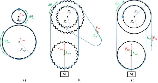
Figure 1. Principle of operation of state-of-the-art cable and chain reducers: (a) cable capstan drive, (b) Weston’s differential pulley block, and (c) cable differential pulleys.
Similar systems using cables instead of chains also exist (see Figure 1c). Such mechanisms, making use of a differential pulley, are commonly used for the purpose of teaching the theory of machines (see for example the wheel and differential axle proposed by P.A. Hilton Ltd, Stockbridge, UK, http//www.p-a-hilton.co.uk/). The principle of operation and the reduction ratio are the same as for the Weston’s differential pulley block. With a cable instead of a chain, however, the radii can be chosen arbitrarily close to each other, thus an even higher reduction ratio can be obtained. It is worth noting that, contrary to the cable capstan drive, the bulkiness of the system is independent of the reduction ratio, hence a potentially more compact solution when a high reduction ratio is required. Additionally, this mechanism remains highly transparent and backdrivable. However, in its current form, is can only pull an output load (mass M on Figure 1c) in one direction. This is not convenient for a robot’s joint which moves in opposite directions.
In this paper, we propose to combine two properly-synchronized input differential pulleys with an output pulley similar to a cable capstan drive’s one to control a robot joint. The principle of operation of such a bi-directional differential cable drive actuator, which combines the advantages of both systems, is explained in the next subsection.
3.2. Principle of Operation of the Differential Cable Drive Actuator
As shown in Figure 2, in order to obtain a high reduction ratio cable drive, we propose here to combine two synchronized input differential pulleys with an output pulley similar to a cable capstan drive’s one (in practice, the same differential pulley is used in both directions, the larger pulley in one direction being the smaller in the opposite direction, and vice versa). The principle of operation is similar to a Weston’s differential pulley block or cable differential pulleys, except that the differential pulleys are used here as the input instead of an intermediate block of pulleys (the cable being conversely used as an intermediate mean of transmission instead of the input of the system) and the pulley moving in translation is used here as an intermediate idler pulley, the output being a separate pulley similar to the output pulley of a cable capstan drive.
Figure 1.Principle of operation of state-of-the-art cable and chain reducers: (a) cable capstan drive, (b) Weston’s differential pulley block, and (c) cable differential pulleys.
Similar systems using cables instead of chains also exist (see Figure1c). Such mechanisms, making use of a differential pulley, are commonly used for the purpose of teaching the theory of machines (see for example the wheel and differential axle proposed by P.A. Hilton Ltd, Stockbridge, UK, http//www.p-a-hilton.co.uk/). The principle of operation and the reduction ratio are the same as for the Weston’s differential pulley block. With a cable instead of a chain, however, the radii can be chosen arbitrarily close to each other, thus an even higher reduction ratio can be obtained. It is worth noting that, contrary to the cable capstan drive, the bulkiness of the system is independent of the reduction ratio, hence a potentially more compact solution when a high reduction ratio is required. Additionally, this mechanism remains highly transparent and backdrivable. However, in its current form, is can only pull an output load (mass M on Figure1c) in one direction. This is not convenient for a robot’s joint which moves in opposite directions.
In this paper, we propose to combine two properly-synchronized input differential pulleys with an output pulley similar to a cable capstan drive’s one to control a robot joint. The principle of operation of such a bi-directional differential cable drive actuator, which combines the advantages of both systems, is explained in the next subsection.
3.2. Principle of Operation of the Differential Cable Drive Actuator
As shown in Figure2, in order to obtain a high reduction ratio cable drive, we propose here to combine two synchronized input differential pulleys with an output pulley similar to a cable capstan drive’s one (in practice, the same differential pulley is used in both directions, the larger pulley in one direction being the smaller in the opposite direction, and vice versa). The principle of operation is similar to a Weston’s differential pulley block or cable differential pulleys, except that the differential pulleys are used here as the input instead of an intermediate block of pulleys (the cable being conversely used as an intermediate mean of transmission instead of the input of the system) and the pulley moving in translation is used here as an intermediate idler pulley, the output being a separate pulley similar to the output pulley of a cable capstan drive.
Actuators 2016, 5, 17 8 of 26
Figure 2. Principle of a differential cable drive.
A primary cable (thin solid lines in Figure 2) is attached to the first input pulley of radius , wound around a first idler pulley and attached to the second pulley of radius with . If the first input pulley turns clockwise of an angle , the cable unwinds from this pulley of a length equal to = × . Both input pulleys being attached together, the second input pulley also turns clockwise of an angle . Thus a length of cable equal to = × winds around it. As a consequence, the free part of the cable between the input pulleys shortens. For a rotation of an angle , the shortening equals half the difference (provided the cable is maintained in tension and the two cable strands between the input pulleys and the idler pulley are parallel) and the idler pulley gets closer to the input pulleys from a distance = ( − )/2 × . If the idler pulley is, itself, attached to an output pulley of radius through a secondary cable (large solid line in Figure 2), the later turns counterclockwise of an angle:
= / = ( − )/(2 × ) × (5)
Hence, by denoting the (motor) input torque and the output (joint) torque, the reduction ratio of the differential cable drive is given by:
= / = / = (2 × )/( − ) (6)
Conversely, a second idler pulley and a second strand of the primary cable and of the secondary cable (broken lines in Figure 2) are used to drive the output pulley clockwise.
As can be seen from Equation (6), the reduction ratio is no more defined as the ratio between some pulleys radii but as the ratio between the output pulley radius and the difference in input pulleys radii. This way, a very high, and potentially infinite, reduction ratio can be easily obtained. Therefore, one has only to manufacture input pulleys with a small difference in diameter. It is worth noting however that in case of a large reduction ratio, the force in the cables increases, and this introduces practical limitations due to cable compliance and resistance limits.
3.3. Dimensioning and Implementation
While the design presented in Figure 2 is relatively simple, its implementation requires the application of precise rules related to cable drive systems. These rules drive the choice of the actuator and cables and the dimensioning of the input, idler, and output pulleys, as well as of the whole reducer, as will be further detailed hereunder.
3.3.1. Actuator Selection
Haptic interfaces and collaborative robots usually make use of ironless DC motors (e.g., from Maxon Motor, Sachseln, Switzerland, http://www.maxonmotor.com/). These actuators have a very high peak torque, a very low inertia, and low cogging. They are also relatively simple to control compared to brushless actuators and come in a large range of sizes. Such actuators are commonly used on commercially available haptic interfaces such as, for example, the well-known Geomagic Touch, Geomagic Touch X and Sensable PHANToM Premium from Geomagic (Cary, NC, USA, http://www.geomagic.com/), Virtuose 3D and Virtuose 6D from Haption (Soulgé-sur-Ouette, France,
Figure 2.Principle of a differential cable drive.
A primary cable (thin solid lines in Figure2) is attached to the first input pulley of radius Rin1,
wound around a first idler pulley and attached to the second pulley of radius Rin2with Rin2ąRin1.
If the first input pulley turns clockwise of an angle δθin, the cable unwinds from this pulley of a length
equal to Lin1“Rin1ˆ δθin. Both input pulleys being attached together, the second input pulley also
turns clockwise of an angle δθin. Thus a length of cable equal to Lin2 “ Rin2ˆ δθin winds around
it. As a consequence, the free part of the cable between the input pulleys shortens. For a rotation of an angle δθin, the shortening equals half the difference (provided the cable is maintained in tension
and the two cable strands between the input pulleys and the idler pulley are parallel) and the idler pulley gets closer to the input pulleys from a distance Lip“ ppRin2´Rin1q {2q ˆ δθin. If the idler pulley
is, itself, attached to an output pulley of radius Routthrough a secondary cable (large solid line in
Figure2), the later turns counterclockwise of an angle:
δθout“Lip{Rout“ ppRin2´Rin1q { p2 ˆ Routqq ˆ δθin (5)
Hence, by denoting Cinthe (motor) input torque and Coutthe output (joint) torque, the reduction
ratio of the differential cable drive is given by:
R “ Cout{Cin“ δθin{δθout“ p2 ˆ Routq { pRin2´Rin1q (6)
Conversely, a second idler pulley and a second strand of the primary cable and of the secondary cable (broken lines in Figure2) are used to drive the output pulley clockwise.
As can be seen from Equation (6), the reduction ratio is no more defined as the ratio between some pulleys radii but as the ratio between the output pulley radius and the difference in input pulleys radii. This way, a very high, and potentially infinite, reduction ratio can be easily obtained. Therefore, one has only to manufacture input pulleys with a small difference in diameter. It is worth noting however that in case of a large reduction ratio, the force in the cables increases, and this introduces practical limitations due to cable compliance and resistance limits.
3.3. Dimensioning and Implementation
While the design presented in Figure2is relatively simple, its implementation requires the application of precise rules related to cable drive systems. These rules drive the choice of the actuator and cables and the dimensioning of the input, idler, and output pulleys, as well as of the whole reducer, as will be further detailed hereunder.
3.3.1. Actuator Selection
Haptic interfaces and collaborative robots usually make use of ironless DC motors (e.g., from Maxon Motor, Sachseln, Switzerland, http://www.maxonmotor.com/). These actuators have a very high peak torque, a very low inertia, and low cogging. They are also relatively simple to control compared to brushless actuators and come in a large range of sizes. Such actuators are commonly used on commercially available haptic interfaces such as, for example, the well-known Geomagic Touch, Geomagic Touch X and Sensable PHANToM Premium from Geomagic (Cary, NC, USA, http://www.geomagic.com/), Virtuose 3D and Virtuose 6D from Haption (Soulgé-sur-Ouette, France, http://www.haption.com/), and delta.x, omega.x and sigma.x from Force Dimension (Nyon, Switzerland, http://www.forcedimension.com/).
In practice, these actuators are usually controlled using a PD (proportional and derivative) position controller (with gains denoted here Kcontand Bcont). The force τhiapplied by the actuators of
the haptic interface when the slave arm or virtual reality avatar is blocked against its environment depends on the difference between the current interface’s angular position qhiand speed
.
qhiand the slave robot’s or avatar’s data qre f and
.
qre f used as a reference [36], through the following equation:
τhi“Kcontˆ ´ qre f ´qhi ¯ `Bcontˆ ´. qre f´q.hi¯ (7)
Such a controller has the advantage of being passive, i.e., stable regardless the operator’s commands and the interactions with the environment. In practice, however, the gains allowing to ensure stability are limited due to the spatial and temporal quantization of the measured positions [37], and must remain within given limits Kcont_max_actuatorand Bcont_max_actuator. When the user tries to turn
the rotor of the motor, he feels a viscoelastic behavior. The highest stiffness that can be rendered is equal to Kcont_max_actuator, called here control stiffness. It is worth noting that these limitations occur at
the actuator level. When a reducer is used between the actuators and links, it can be demonstrated that the stiffness sensed by the user at the joint level is proportional to the reduction ratio square.
Kcont_max_joint“Kcont_max_actuatorˆR2 (8)
When the user manipulates the interface through a handle fixed at the extremity of a link of length L, the apparent stiffness further depends on L. It can be expressed using the following equation:
Kcont_max_handle“Kcont_max_actuatorˆ pR{Lq2 (9)
Hence, to allow for the simulation of rigid environments, the designer can either use high performances actuators, sensors, and electronics (allowing to get a high value of Kcont_max_actuator),
or high reduction ratios, or short links (at the price however of a limited workspace). Of course the actuators’ torques are further filtered by the interface’s mechanical structure.
The reader may observe that previous equations are written for a one degree of freedom (1DOF) interface. The same principle applies to multi DOFs robots, using a reduction matrix instead of a simple scalar reduction ratio, and the Jacobian of the robot instead of the link’s length.
From Equations (6) and (9), it can be seen that both the force capacity and control stiffness of the haptic interface directly depend on the reduction ratio R and link’s length L. The choice of a given actuator and reduction ratio, thus, depends on the desired maximum force feedback capacity and
apparent stiffness which are important design drivers for haptic interfaces and cobots. It can be noticed that, for a given desired force, one can use either a large actuator with a small reducer, or a small actuator and a large reducer, or any intermediate solution. A larger actuator usually allows minimizing complexity and friction, while a smaller actuator minimizes weight (provided the reducer’s increase in weight is not superior to the decrease in weight of the smaller motor) and maximizes the apparent stiffness (which is proportional to the reduction ratio square), even if smaller motors typically have a lower control stiffness than larger ones.
3.3.2. Cable Choice
As for the actuator, the choice of the cables is driven by the desired force and stiffness at the output of the system. Indeed, the secondary cable should be able to resist the force generated by the output joint. With Routthe radius of the output pulley and Cout_maxthe maximum desired output
torque, the highest force in the secondary cable equals:
Fsc_max“Cout_max{Rout (10)
Usually, a cable with a resistance of at least 2 times Fsc_maxis chosen. It is worth noting that metal
cables usually used in such reducers plastically deform when wound on small pulleys. For the most flexible cables found on the market, the minimum diameter of the pulley is about 17 times the cable diameter. Hence, for a secondary cable of diameter dsc, we get Routě8.5 ˆ dsc(at the level of the cable
neutral fiber), and the cable should have a resistance higher than Cout_max{ p8.5 ˆ dscq.
The same holds for the primary cable. With the hypothesis that all cables remain parallel (see below) and under tension, the force in the primary cable is half the force in the secondary one. Hence, a smaller cable with a minimum resistance of Cout_max{ p17 ˆ dscqis required.
It is worth noting that, as for the actuator, the stiffness of the cables should also be taken into account when selecting them. Depending on the size of the system and range of motion, the length of the free strands of the cables (i.e., the sections of the cable in-between the pulleys) can be quite long, introducing flexibilities and decreasing the apparent stiffness sensed by the user. At first sight, the control stiffness Kcont_maxand cables stiffness Kcables(both computed in the same space, being either
the motor space, the joint space or the Cartesian space in which the handle moves) act in series, and both are much lower than the link’s stiffness. Hence, the global apparent stiffness equals:
Kapp_max“
´
K´1cont_max`Kcables´1 ¯´1
(11) Given a desired apparent stiffness and a control stiffness obtained as an output of the motor selection, the required cable stiffness can be computed. Under the assumption that all cables remain parallel and under tension, the four free strands of the primary cable act in parallel, so as the two free strands of the secondary cable, both acting in series. Once the cables have been chosen, the designer can check if the desired stiffness is attained (taking into account the different configurations of the robot as the ratio between the length of the different strands depend on the output angle). If not, the cable selection can be improved.
3.3.3. Dimensioning of the Output Pulley
As said previously, the output pulley must have a minimum radius equal to Rout ě 8.5 ˆ dsc.
In practice, this radius is adjusted depending on other integration constraints, and can be higher than this minimum value.
3.3.4. Dimensioning of the Input Pulleys
Regarding the input pulleys, it must first of all be noted that the rotation of the differential pulleys can be quite large for high reduction ratio. As an example, for a reduction ratio of R = 60 and a range
of motion δθout= 120˝at the joint level, the differential pulley rotates 20 turns (from Equation (6), we
have δθin“R ˆ δθout“7200˝).
The readers must also keep in mind that, as already said in Section2.1, cables have to be wound in spirals around the input pulleys. In practice, to properly guide the cables around the pulleys and avoid any possible overlap, a spiral thread is usually machined at the surface of the pulleys, with a thread pitch p slightly larger than the primary cable diameter dpc(typically about 1.25 times the
cable diameter), the latter depending on the force transmitted in the cable. As a consequence, the cable travels a distance along the pulley axis equal to the number of turns times the thread pitch. Referring to the above example, if 20 turns are required and if a thin primary metal cable of diameter 1 mm as often found in haptic interfaces’ cable drives is used, the cable travels 25 mm along the pulley axis when the joint turns 120˝. This result holds, of course, for both the large and the small pulleys of
the differential.
The last point to mention is the cable fixation on the pulleys. This can be made with screws. In this case the pulleys should be sufficiently long to integrate the screws whose head diameter usually represents about three or four turns for small cables, as presented above. Alternatively, the cables can simply be locked by friction. The friction between the cable and pulley being an exponential function of the winding angle, it does not slide on the input pulley if this angle is sufficient. In practice, four to five turns are usually sufficient to avoid cable slippage. Both methods are illustrated in Figure3, which also summarizes the aforementioned dimensioning rules (in Figure3, the input pulleys are represented at the center of the workspace with the hypothesis that the joint can turn δθout{2 clockwise
and counterclockwise, the global range of motion being equal to δθout).
Actuators 2016, 5, 17 11 of 26
represented at the center of the workspace with the hypothesis that the joint can turn /2 clockwise and counterclockwise, the global range of motion being equal to ).
Figure 3. General rules of dimensioning of the input and idler pulleys.
One can see that the length of the input pulley is smaller with a cable friction locking compared to screw attachments. One could conclude that friction locking is desirable on both pulleys. This would however require a closed cable loop. This in turn would require both ends of the cable to be attached together. This would result in practice in a cable bulge which would introduce perturbations when the cable is wound around the pulleys. To avoid this problem, we recommend a cable friction locking on one pulley and a screw attachment on the second one.
It is also worth noting that Equations (5) and (6) require that the primary cable strands remain parallel to each other. If not, the geometry of the quadrangle formed by the input and output points of the primary cable on the input pulleys and each of the idler pulleys will deform when the system moves, consuming part of the elongation or shortening of the cable and modifying the reduction ratio which would further depend on the joint angle. This parallelism introduces constraints on both the input and idler pulleys dimensions (see below for the later). In particular, one can see from Figure 3 that the primary cables will “advance” along the input pulleys when the system moves. If the direction of the spiral thread is not the same on both pulleys, the distance between the input and output points of the primary cable on the input pulleys, and hence the angle between the primary cable strands, will change as a function of the pulleys’ angle. To maintain these strands parallel, the direction of the spiral thread must be the same on both input pulleys. Additionally, we introduce a small distance between the two strands going in and out of the input pulley with screw attachments in order to avoid the cable strands to collide and rub against each other. In practice, this distance is set at the same value as the length of the friction locking on the other pulley (see details below).
Regarding the pulleys’ diameter, it is mostly limited by the minimum winding diameter of the primary cable, with the same rules as for the secondary cable, i.e., & ≥ 8.5 × . Then, the difference in pulleys diameter is directly function of the chosen actuator which fixes the reduction ratio and the output pulley’s radius through Equation (6).
3.3.5. Dimensioning of the Idler Pulleys
For the same reason as explained above, the diameter of the idler pulleys must be equal to the distance between the output point of the primary cable from one input pulley and its input point on the second input pulley. If not, the cable strands will not remain parallel as the system moves.
Figure 3.General rules of dimensioning of the input and idler pulleys.
One can see that the length of the input pulley is smaller with a cable friction locking compared to screw attachments. One could conclude that friction locking is desirable on both pulleys. This would however require a closed cable loop. This in turn would require both ends of the cable to be attached together. This would result in practice in a cable bulge which would introduce perturbations when the cable is wound around the pulleys. To avoid this problem, we recommend a cable friction locking on one pulley and a screw attachment on the second one.
It is also worth noting that Equations (5) and (6) require that the primary cable strands remain parallel to each other. If not, the geometry of the quadrangle formed by the input and output points of the primary cable on the input pulleys and each of the idler pulleys will deform when the system moves, consuming part of the elongation or shortening of the cable and modifying the reduction ratio which would further depend on the joint angle. This parallelism introduces constraints on both the
input and idler pulleys dimensions (see below for the later). In particular, one can see from Figure3
that the primary cables will “advance” along the input pulleys when the system moves. If the direction of the spiral thread is not the same on both pulleys, the distance between the input and output points of the primary cable on the input pulleys, and hence the angle between the primary cable strands, will change as a function of the pulleys’ angle. To maintain these strands parallel, the direction of the spiral thread must be the same on both input pulleys. Additionally, we introduce a small distance between the two strands going in and out of the input pulley with screw attachments in order to avoid the cable strands to collide and rub against each other. In practice, this distance is set at the same value as the length of the friction locking on the other pulley (see details below).
Regarding the pulleys’ diameter, it is mostly limited by the minimum winding diameter of the primary cable, with the same rules as for the secondary cable, i.e., Rin1&Rin2ě8.5 ˆ dpc. Then, the
difference in pulleys diameter is directly function of the chosen actuator which fixes the reduction ratio and the output pulley’s radius through Equation (6).
3.3.5. Dimensioning of the Idler Pulleys
For the same reason as explained above, the diameter of the idler pulleys must be equal to the distance between the output point of the primary cable from one input pulley and its input point on the second input pulley. If not, the cable strands will not remain parallel as the system moves.
With the approximation that the angle between the input and output points of the primary cable on the input pulleys equals 180˝, the diameter of the idler pulleys can be computed using the following
formula (see Figure3for the notations):
dip1“ c pRin2´Rin1q2` ´ Lrom`Lsh`Lf s`1 ¯2 (12) dip2“ c pRin2´Rin1q2` ´ Lrom`Lf l`Lsh`1 ¯2 (13) On can see that the idler pulleys can have the same diameter if the distance between the two strands going in and out of the input pulley with screw attachments is equal to the length of the friction locking (Lf s“Lf l). In order to simplify the design and manufacturing of the system, we
recommend respecting this constraint. 3.3.6. Global Dimensioning of the System
The radii of the different pulleys being known, the distance between the input and output pulleys can be fixed. Indeed, as shown on Figure4, when the output pulley turns of an angle ˘δθout{2, the
idler pulleys travel a distance equal to Lip “ ˘ pδθout{2q ˆ Rout. Hence, the distance between the
input and output pulleys must be larger than dip1`Lipand dip2`Lipplus a small margin to avoid
inter-pulley collisions. It is worth noting that, as can be seen from Figures3and4, some primary cables cross the paths of the idler pulleys when the latter moves toward the input pulleys. As a consequence, the distance between the pulleys must be increased to avoid collisions between the cables and idler pulleys. In practice, the occurrence of these collisions depends on the pulleys diameter and on the angle between the cables going in both directions and the distance between the input and output pulleys must be adjusted iteratively until no collision remains. This can be accomplished with a CAD software.
It is also worth noting that, as the input cables “advance” along the input pulleys when the system rotates, the distance between the point Pin1(respectively, Pin2) defined as the middle of the
input and output points of the primary cable on the input pulleys and the point Pout1(respectively,
Pout2) defined as the input of the secondary cable on the output pulley (this distance can be considered
as some “virtual” length of the cables between the input and output pulleys) varies as a function of the output joint’s angle. As a consequence, the length of the free cable strands slightly changes when the system moves. In practice, however, the aforementioned constraints impose that the “virtual” length
Actuators 2016, 5, 17 13 of 26
of the cables is very large compared to the cable advance along the pulleys’ axis and this elongation is negligible. As an example, the maximum elongation of the cables of the prototype presented below equals 0.14% of the cables’ length [38].
With the approximation that the angle between the input and output points of the primary cable on the input pulleys equals 180°, the diameter of the idler pulleys can be computed using the following formula (see Figure 3 for the notations):
= ( − ) + ( + + + 1) (12)
= ( − ) + ( + + + 1) (13)
On can see that the idler pulleys can have the same diameter if the distance between the two strands going in and out of the input pulley with screw attachments is equal to the length of the friction locking ( = ). In order to simplify the design and manufacturing of the system, we recommend respecting this constraint.
3.3.6. Global Dimensioning of the System
The radii of the different pulleys being known, the distance between the input and output pulleys can be fixed. Indeed, as shown on Figure 4, when the output pulley turns of an angle /2, the idler pulleys travel a distance equal to = ( /2) × . Hence, the distance between the input and output pulleys must be larger than + and + plus a small margin to avoid inter-pulley collisions. It is worth noting that, as can be seen from Figures 3 and 4, some primary cables cross the paths of the idler pulleys when the latter moves toward the input pulleys. As a consequence, the distance between the pulleys must be increased to avoid collisions between the cables and idler pulleys. In practice, the occurrence of these collisions depends on the pulleys diameter and on the angle between the cables going in both directions and the distance between the input and output pulleys must be adjusted iteratively until no collision remains. This can be accomplished with a CAD software.
Figure 4. Global dimensioning of the differential cable drive.
It is also worth noting that, as the input cables “advance” along the input pulleys when the system rotates, the distance between the point (respectively, ) defined as the middle of the input and output points of the primary cable on the input pulleys and the point (respectively, ) defined as the input of the secondary cable on the output pulley (this distance can be considered as some “virtual” length of the cables between the input and output pulleys) varies as a function of the output joint’s angle. As a consequence, the length of the free cable strands slightly changes when the system moves. In practice, however, the aforementioned constraints impose that the “virtual” length of the cables is very large compared to the cable advance along the pulleys’ axis and this elongation is negligible. As an example, the maximum elongation of the cables of the prototype presented below equals 0.14% of the cables’ length [38].
Figure 4.Global dimensioning of the differential cable drive. 3.3.7. Dimensioning Methodology
The equations presented above theoretically allow the successive dimensioning of the different components. In practice, the different choices are interdependent and the dimensioning of a differential cable drive is an iterative process.
Additionally, the theoretical values obtained as an output of the dimensioning process can be adapted due to other constraints as for example integration or cost constraints.
4. Development and Manufacturing of a Differential Cable Drive Actuator Prototype
4.1. Context of the Study
Given the potential advantages of differential cable drives, we decided to develop a 1-DOF prototype robot integrating such a reducer. In order to set the design drivers, we selected as a use-case a maxilla facial surgery simulator developed within the framework of the European Integrated Project SKILLS (IST-FP6 #035005, 2006–2011). This use-case has stringent requirements in terms of both transparency in free space and force quality rendering when force feedback is required, for which differential cable drives appear as a promising solution.
This simulator is a multimodal VR platform for the training of surgery skills [39], focusing more specifically on an operation called the Epker osteotomy which consists in moving the lower mandible forward or backward to correct an improper positioning of the teeth in the case of malformation or trauma. Therefore, the surgeon has in particular to drill the mandible bones. Experimental measurements made with a motion capture system and a force sensor during a data acquisition campaign performed in the anatomy laboratory of a university hospital with which we collaborated during these developments have shown that the most critical steps of this surgery require bi-manual movements in the Cartesian space with a maximum amplitude at the level of the surgery tool handle of about 162 to 194 mm in translation and 137˝in orientation. The maximum measured efforts on the handle are in the order
of 25 N and 1.5 N¨m (also in the Cartesian space). Finally, the bone stiffness is about 10,000 N/m. To allow for the simulation of this surgery, similar displacements and forces have to be reproduced at the level of the robot’s handle. Therefore, we developed two robots (one for each hand) having a hybrid serial and parallel architecture. As shown on Figure5, these robots are composed of two 3-DOFs sub-structures connected together at their tip and equipped with an additional pivot DOF in series. This structure combines the advantages of serial (large workspace in orientation) and parallel robots (good transparency in orientation). In practice, the left hand robot is a reconditioned version
Actuators 2016, 5, 17 14 of 26
of a master arm previously designed for abdominal telesurgery, and the right hand robot is a new haptic interface with a higher force capacity and stiffness specifically developed for this platform. Further details on these robots can be found in [23,24].
3.3.7. Dimensioning Methodology
The equations presented above theoretically allow the successive dimensioning of the different components. In practice, the different choices are interdependent and the dimensioning of a differential cable drive is an iterative process.
Additionally, the theoretical values obtained as an output of the dimensioning process can be adapted due to other constraints as for example integration or cost constraints.
4. Development and Manufacturing of a Differential Cable Drive Actuator Prototype
4.1. Context of the Study
Given the potential advantages of differential cable drives, we decided to develop a 1-DOF prototype robot integrating such a reducer. In order to set the design drivers, we selected as a use-case a maxilla facial surgery simulator developed within the framework of the European Integrated Project SKILLS (IST-FP6 #035005, 2006–2011). This use-case has stringent requirements in terms of both transparency in free space and force quality rendering when force feedback is required, for which differential cable drives appear as a promising solution.
This simulator is a multimodal VR platform for the training of surgery skills [39], focusing more specifically on an operation called the Epker osteotomy which consists in moving the lower mandible forward or backward to correct an improper positioning of the teeth in the case of malformation or trauma. Therefore, the surgeon has in particular to drill the mandible bones. Experimental measurements made with a motion capture system and a force sensor during a data acquisition campaign performed in the anatomy laboratory of a university hospital with which we collaborated during these developments have shown that the most critical steps of this surgery require bi-manual movements in the Cartesian space with a maximum amplitude at the level of the surgery tool handle of about 162 to 194 mm in translation and 137° in orientation. The maximum measured efforts on the handle are in the order of 25 N and 1.5 N∙m (also in the Cartesian space). Finally, the bone stiffness is about 10,000 N/m. To allow for the simulation of this surgery, similar displacements and forces have to be reproduced at the level of the robot’s handle. Therefore, we developed two robots (one for each hand) having a hybrid serial and parallel architecture. As shown on Figure 5, these robots are composed of two 3-DOFs sub-structures connected together at their tip and equipped with an additional pivot DOF in series. This structure combines the advantages of serial (large workspace in orientation) and parallel robots (good transparency in orientation). In practice, the left hand robot is a reconditioned version of a master arm previously designed for abdominal telesurgery, and the right hand robot is a new haptic interface with a higher force capacity and stiffness specifically developed for this platform. Further details on these robots can be found in [23,24].
(a) (b)
Figure 5. The SKILLS multimodal VR platform for the training of surgery skills. (a) overview of the platform used by a surgeon; (b) close-up view of the robots.
Figure 5.The SKILLS multimodal VR platform for the training of surgery skills. (a) overview of the platform used by a surgeon; (b) close-up view of the robots.
4.2. Dimensioning and Design of the Differential Cable Drive Actuator Prototype 4.2.1. Design Drivers
With the idea to develop a prototype compatible with the SKILLS VR-platform, we used the specifications of the second axis of the SKILLS robot to set the prototype’s design drivers. The joint’s range of motion should be in the order of 131˝and the prototype actuator should be able to develop
a force of 15.5 N and display an apparent control stiffness of 5000 N/m at a distance of 340 mm from the joint axis. Thus, a joint torque of 5.27 N¨m is required.
4.2.2. Actuator Selection
After a careful study of the available actuators and an optimization of the motor-reducer association, a Maxon Motor RE25 118746 (24 V, 10 W, 0.0288 N¨m permanent torque) was selected, in association with a precise (i.e., 3600 ppt) rotor encoder.
To drive this actuator, we used a controller manufactured by Haption based on research results from CEA LIST [40]. This controller implements a temperature model allowing the limiting of the input current and avoiding overheating and destroying the motor. In order to allow soliciting the actuator up to about 30 s, the input current is limited to three times the maximum continuous current. The peak torque is thus three times higher than the nominal torque. It is equal to 0.0864 N¨m.
This results in a required reduction ratio of 61:1 (please note that this value is obtained given the choice of actuator and controller, for a different choice another ratio would be required but the principles presented below would remain the same).
4.2.3. Cables Choice
A miniature steel cable of diameter dpc= 0.95 mm is selected between the input pulleys and
the reducer idler pulleys. This cable is highly flexible, yet of sufficient diameter to resist the motor torque. It can be wound on pulleys with minimum radius Rin_min“8.1 mm. Even if a larger cable
with a higher stiffness could have been used here, as the reduction ratio no more depends on the input pulley’s diameter as with conventional capstan cable drives, this would increase the bulkiness of the reducer as will we demonstrate hereafter. A second miniature steel cable with a larger diameter (dsc= 1.80 mm) is used between the reducer idler pulleys and the output pulley.
4.2.4. Dimensioning of the Output Pulley
With a secondary cable of diameter dsc= 1.80 mm, the output pulley’s radius should be larger
than Rout_min “15.3 mm. In practice, however, as shown on Figure6, the differential cable drive
studied in this section differs from the system shown on Figures2and4from two respects.
Firstly, the device is statically balanced with a counterweight. Such a counterbalancing system, being either passive or active, is necessary on haptic interfaces in order to limit the fatigue of the user and avoid the system to fall in case the user drops the handle. To be efficient, such a counterweight should be either sufficiently heavy or placed at a sufficient distance from the joint’s axis. The maximum reasonable weight fixed the distance which in turn constrained the pulley’s diameter (we chose to directly fix the counterweight on the output pulley). This results in an output pulley of radius Rout= 50 mm (at the level of the neutral cable fiber).
Secondly, the secondary cable is not directly attached to the output pulley. As shown on Figures6
and7, it goes first around guiding pulleys. This is due to the fact that, even if the developed prototype has only one actuated DOF, it is representative of the second axis of the robots illustrated in Figure5
(called Axis 2 in Figure7). As a consequence, the proposed design also integrates a passive moving axis (called Axis 1 in Figure7) representative of the first axis if these robots. Hence, two additional guiding idler pulleys (with radius Rgp = 20 mm here and distant from Dgp = 80 mm) are used to
modify the output cable trajectory and guide it along the first axis of rotation of the robot. This way, movements around axis 1 and axis 2 are decoupled, i.e., the robot can rotate around axis 1 without any modification of the angle around axis 2 (this modification has no influence on the principle of operation of the reducer). Additionally, as shown in Figure6, the actuator and reducer are placed on the side of the sagittal plane of the prototype. It is, thus, possible to integrate a second actuator in order to actuate the third axis of the robot.
Actuators 2016, 5, 17 15 of 26 principle of operation of the reducer). Additionally, as shown in Figure 6, the actuator and reducer are placed on the side of the sagittal plane of the prototype. It is, thus, possible to integrate a second actuator in order to actuate the third axis of the robot.
Figure 6. CAD design of the prototype differential cable drive.
4.2.5. Dimensioning of the Input Pulleys
In order to obtain a reduction ratio of 61:1, we made use of input pulleys with radii = 8.5 mm and = 10.14 mm (at the level of the neutral cable fiber). These dimensions, both larger than _ = 8.1 mm, are illustrated in Figure 7 and serve in the CAD design shown in
Figure 6.
Figure 7. Dimensions of the prototype differential cable drive.
Figure 8 shows additional details on the dimensions of the input pulleys. A first end of the input cable is attached at the first end of the second input pulley using a screw. It is then wound around the pulley, with a sufficient number of turns to allow for half the joint’s range of motion in one sense. Then the cable exits the pulley, is wound around a first reducer idler pulley and enters the first input pulley. It is then wound around the pulley, with a sufficient number of turns to avoid slipping (here 4.5 turns are sufficient). Then it exits the first input pulley, is wound around the second reducer idler pulley, and enters the second input pulley around which it is wound with a sufficient number of turns to allow for half the joint’s range of motion in the other sense. Finally, the second end of the cable is attached to the second input pulley using a screw. It is worth noting that 11.1 turns of cable must be left free on both sides of the cable wound around the first input pulley to allow for the cable
Figure 6.CAD design of the prototype differential cable drive. 4.2.5. Dimensioning of the Input Pulleys
In order to obtain a reduction ratio of 61:1, we made use of input pulleys with radii Rin1= 8.5 mm
and Rin2 = 10.14 mm (at the level of the neutral cable fiber). These dimensions, both larger than
Rin_min“8.1 mm, are illustrated in Figure7and serve in the CAD design shown in Figure6.
Figure8shows additional details on the dimensions of the input pulleys. A first end of the input cable is attached at the first end of the second input pulley using a screw. It is then wound around the pulley, with a sufficient number of turns to allow for half the joint’s range of motion in one sense. Then the cable exits the pulley, is wound around a first reducer idler pulley and enters the first input pulley. It is then wound around the pulley, with a sufficient number of turns to avoid slipping (here 4.5 turns are sufficient). Then it exits the first input pulley, is wound around the second reducer idler pulley, and enters the second input pulley around which it is wound with a sufficient number of turns to allow for half the joint’s range of motion in the other sense. Finally, the second end of the cable is attached to the second input pulley using a screw. It is worth noting that 11.1 turns of cable must be left free on both sides of the cable wound around the first input pulley to allow for the cable to move along this pulley when the joint moves half its range of motion in both senses (the range of motion is 131˝here,