HAL Id: in2p3-00007813
http://hal.in2p3.fr/in2p3-00007813
Submitted on 27 Nov 2013
HAL is a multi-disciplinary open access
archive for the deposit and dissemination of
sci-entific research documents, whether they are
pub-lished or not. The documents may come from
teaching and research institutions in France or
abroad, or from public or private research centers.
L’archive ouverte pluridisciplinaire HAL, est
destinée au dépôt et à la diffusion de documents
scientifiques de niveau recherche, publiés ou non,
émanant des établissements d’enseignement et de
recherche français ou étrangers, des laboratoires
publics ou privés.
beams at the SPIRAL facility
B. Laune, M. Malard, R. Anne, L. Boy, D. Bibet, J. Guillot, E. Lécorché, B.
Piquet, B. Raine, C. Tribouillard, et al.
To cite this version:
B. Laune, M. Malard, R. Anne, L. Boy, D. Bibet, et al.. Diagnostic system dedicated to the radioactive
ion beams at the SPIRAL facility. 15th International Conference on Cyclotrons and their Applications,
Jun 1998, Caen, France. pp.163-166. �in2p3-00007813�
DIAGNOSTIC SYSTEM DEDICATED TO THE RADIOACTIVE ION BEAMS AT THE
SPIRAL FACILITY
B. LAUNE, M. MALARD
Institut de Physique Nucleaire (CNRS/IN2P3) 91406 Orsay Cedex, France
R. ANNE, L. BOY, D. BIBET, J. GUILLOT, E. LECORCHE, B. PIQUET,
B. RAINE, C. TRIBOUILLARD, M. ULRICH, A. C. C. VILLARI
GANIL (CEA/DSM, CNRS/IN2P3) 14076 Caen Cedex 5, France
In order to be able to tune the CIME cyclotron and the associated beam lines with the radioactive ion beams, dedicated diagnostic sytems have been built. This equipment will be described in details. The first tests with reduced intensity stable beams will also be reported.
1
Introduction
The SPIRAL Radioactive Ion Beam (R.lB.) Facility has already been described elsewhere [1J: it is designed to post accelerate through a K265 isochronous cyclotron the R.I.B.'s which are produced by the ISOL method, in a target hit by the present GANIL beam, boosted in intensity [2J. The R.lB. 's will be accelerated in a wide range of energy (2. to 25. MeV/A) and intensity (from a few pps up to 5.108 pps).
The cyclotron and beam lines will be pretuned with a known stable beam, and a shift of frequency and/or mag-netic field applied [3J for the R.I.B. Diagnostics work-ing with normal stable beams are implemented [4], but nevertheless a possibility of checking the correct tuning with dedicated diagnostics has been felt necessary. This sytems will be described as well as the results of prelim-inary tests with reduced intensity stable beams.
The current measurement electronics has been made sensitive (down to a few pA): it is based on a logarithmic amplifier [5J.
2
Low energy Beam Line
As the mass selection in the injection line [1 J is rather moderate (R=200), the beams out of the target will not be enough separated. It is then of limited interest to implement dedicated diagnostics systems unless the ra-dioactive ions are detected through their rara-dioactive de-cay: this is the reason why a identification station, based on measurement of radioactive properties, is being in-stalled in the beam line: the beam can be directed to-wards it with a switchyard. This station is described in details elsewhere [6J and will be extremely useful in measuring the production rate of the R.I.B.'s (the one of interest as well as the others) prior to the acceleration.
3
Cyclotron
It is important to tune the isochronism of the cyclotron for the desired radioactive specie, this is why the cy-clotron will be equipped with two radial probes:
- a normal intensity one, but equipped with a re-tractable plastic scintillator, in the valley between the two parts of the electrostatic deflector [4], - a dedicated one, in a hill, with silicon detectors and
associated preamplifiers.
It should be pointed out that both probes are equip-ped with a vacuum lock and carry a NMR probe for pre-cise mesurement of the magnetic field and control when a shift of magnetic field is made.
The purpose of the scintillator is the measurement of the phase and the phase width of the beam(s), the plas-tic scintillator being rather robust and, if the intensity is sufficiently reduced, one can insert the Si, for identifi-cation (E.6.E), energy and energy dispersion measure-ment. If the scintillator can withstand without damage (and still counts) rates up to 106 pps, the maximum rate
accepted by the encoders being a few 104 pps, the phase
measurement is limited to that rate. However the max-imum rate the silicon detector can accept is 103 pps, so
that caution is mandatory for its use.
As far as the scintillator is concerned, the light is transmitted to a photomultiplier located outside the mag-netic field through a liquid optical fiber. Experiments using the GANIL CSS2 have been performed with this set up [7] and demonstrated the usefulness and capa-bility of such a device, but also that the required mini-mum of energy to trigger the electronics is around 1 to 2 MeV/A, according to the mass. Also mass measure-ments with CSS2 has also demonstrated the diagnostics power of silicon detectors inside a cyclotron [8].
4
Medium Energy Beam Line
Different low intensity diagnostics equipments will be im-plemented at different locations of the line:
- ionization chambers [9J for profile measurements, the working intensity of these devices ranges from 102 up to 107 pps, intensity where the secondary
emission profile monitors are effective. Those ion-ization chambers are very rugged and the same electronics as for the SEM profile monitor are used, - scintillators, on a 3-position actuator, so that if
the scintillator gets accidentely burnt, it is moved to the next position for the beam to hit new scin-tillating material,
- Si detectors (E.6.E) for the correct tuning of the Alpha spectrometer, particularly in case of separa-tion of isobars, by energy loss in a thick target. Diagnostics boxes, with a silicon detector, a scintilla-tor and an ionization chambers will be located just at the exit of the cyclotron and right after the Alpha spectrom-eter, while an ionization chamber will be, in addition, at the object point of the spectrometer.
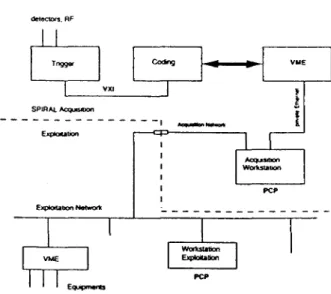
Schematics -SPIRAL Acqulsit/onlExploltaUon
detectors. AF vx, SPIRAl AcQuIsIOon
-
-
-
--- - -
- --
--
--,
--セセ@ イMセ^MMMMMMMMMG@ pcp -PCP
Figure 1: Principles of Acquisition
5
Acquisition
To be able to use these diagnostics which are in fact standard nuclear detectors, we have chosen to take ad-vantage of the GANIL experience on data acquisition and treatment [lOJ. All the detectors will be hooked to a common acquisition. The principle is shown on fig-ure 1. We will be able for the final version to use the new generation of trigger that the GANIL Acquisition Group is developing. But as the data should be used to tune cyclotron and beam lines, ways of communication have to be established between the acquisition world and the standard Control System of SPIRAL. For example, data on phase measurements have to be extracted from the spectra given by the detectors and transmitted to the automatic isochronism tuning task which normally takes the data from the phase probes. In addition, the position of each radial probe must be correlated on a real time basis: the position is digitized when a particle triggers the electronics. Data may be taken "on the fly" or step-by-step in order to adjust to the particle flux. The "START" signal is given by triggered event on the detector and the "STOP" by the RF.
6
Stable Beam Tests
For the tests, a limited version of the acquisition is set up, with CAMAC and VME crates for the control and digital conversion. The following detectors only have been installed:
- scintillator on the valley radial probe, a fast plas-tic scintillator BC418 from Eurisys, ¢ 15 mm, the width seen by the beam being 14 mm,
- silicon detector on the hill radial probe. We will use a 300 J-Lm thick, 15x15 mm2 detector from
Eu-risys, with only 0.5 mm of dead area on one side, because of the small turn separation,
- right at the exit of the cyclotron, a 300 J-Lm thick,
¢ 11 mm Si detector mounted on an actuator, also from Eurisys.
The beam intensity is reduced by a pepperpot (1/10 000) and by closing the slits at the object point of the Low Energy beam line selecting magnet. The high sensitivity of the current measurement allows the secure setting of this low intensity: beams of, say, 10 pA are obtained on the radial probe by closing the slits, and hence insert-ing the pepperpot puts the final intensity well below the lethal rate for the scintillator. Counting on the scintil-lator is then a way to control the insertion of the silicon detector.
セM N@
. Ch."Ill : SPIIW. No.,. : 1
.
- セ@ セMMセMM セMMMMセMMNMMMMMMMMMM .. -_. \'1[\1'001 ""'" , 2 . • : 13 S: 10 l'KI_MYlllLMf2 ill. QII ....
400.-.
II1II. - - r - MMMMセMM \'U:11l'ORT !it.. : 1 \'1[\1'001 "'''' , •• : 13 S: 10 PIIIIJ" L DIE YDl .
••
••
400 .II1II .
... _._ .. __ ._ ...
⦅セ⦅LLAAYNAAAAN⦅@.... __ ... _ _ ___ . ___ ... _________ ...
セ@__ ... __ .. __ ._ .... ___ .. _
.... _._ ... _._._ ..
⦅セNセ@Figure 2: Examples of spectra obtained by scanning the radial probe. The total phase width of the beam is around 250. These spectra were taken for different RF voltages. At the lower left corner, an example of a projection in the top left spectrum, is shown.
The display of such a slice is possible at any probe location.
6.1
Scintillator tests
The intensity has been reduced as described and the phase and phase extension has been measured with the
セXPTK@ beam (around 11 MeV /amu at extraction). Ex-amples of spectra are shown on figure 2. It allowed a better insight on what was happening during the beam 10ss[11], in particular showing that the beam was per-fectly isochronous. The background was very high be-cause of a poor light transmission, due a loose contact between the scintillator and the light guide, that will be fixed.
6.2 Silicon detector tests
A silicon detector, sensitive to the vertical position has been mounted. Unfortunately, it was partially damaged, because it was too close to the circulating beam. In par-ticular the energy measurement was not reliable. When the beam tests will restart, a new detector will be in-stalled and better protected from the normal intensity beam. However, current measurement (counting) and vertical sensitivity could be used to help diagnose the CIME beam loss prior to extraction
[11].
7
Conclusion
SPIRAL will be equipped with detectors allowing the fine tuning of both the cyclotron and the beam lines, from intensity ranging from a few pps up to the normal intensity. The stable beam allowed us to test most of the diagnostic systems and procedures that will be used for the radioactive ion bearns, with the exception of the identification station, that needs to await the R.I.B.'s. Production and acceleration of R.I.B. 's are expected dur-ing the first semester of99. Nevertheless the stable beam tests must continue to improve the operation (and the protection) of the diagnostics, in particular, more work has to be done to extract the right information from the spectra in order to tune the cyclotron in an userfriendly way. These detectors provide detailed information about the beam properties and, since they are available, can be used with stable beams, but with a dependable intensity reduction, i. e. using pepperpots and not by emittance limitation through slits.
AcknowledgeIllents. It is a pleasure to thank L.
La-vergne, J. Lebris (IPN Orsay) for their help with the Si detector and the associated preamplifier, respectively, as well as the GANIL Acquisition, Physics and Operation groups for their constant support and help.
References
[1] M. Lieuvin and the SPIRAL Group, Status of SPI-RAL, the Radioactive Ion Beam Project at GANIL, Proceedings of the 14th International Conference on Cyclotrons and their Applications, Cape Town, 1995, World Scientific.
[2] E. Baron, Experience with the High Intensity Oper-ation of the G ANIL Facility, this conference. [3] L. Boy, A. Chabert, Ch. Ricaud, B. Laune, Tuning
Methods for the SPIRAL Facility, Nuclear Instru-ments and Methods A 400 (1997) 1-8.
[4] B. Laune, The Diagnostics System for the SPIRAL R.I.B. Facility, Proceedings of the 14th International Conference on Cyclotrons and their Applications, Cape Town, 1995, World Scientific.
[5] C. Jamet, E. Petit, Beam Current Measurement with Logarithmic Converter, this conference.
[6] S. Kandri-Rody et al., Identification System for SPI-RAL, this conference.
[7] 1. Boy, D. Bibet, M.H. Moscatello, B. Laune, A.C. Mueller, Cyclotron isochronism tuning by phase mea-surements with a fast scintillator at very low
inten-sity, Nuclear Instruments and Methods A 399 (1997) 195-201
[8J G. Auger et al., Nuclear Instruments and Methods A 350 (1994) 235-243.
[9] R. Anne, Y. Georget, Chambres
a
circulation de gaz, etalonnage avec Ie faisceau GANIL, GANIL Internal Report RA.YG.627[10] B. Raine, M. Tripon, B. Piquet, the Standard GANIL Data Acquisition System, Eighth Conference on Real-Time Computer Applications in Nuclear, Particle and Plasma Physics, Vancouver, 1993 [11] M.P. Bourgarel and the SPIRAL group, SPIRAL
Facility: First results on the CIME cyclotron with stable ion beams, this conference.