HAL Id: halshs-00323675
https://halshs.archives-ouvertes.fr/halshs-00323675
Preprint submitted on 29 Sep 2008
HAL is a multi-disciplinary open access
archive for the deposit and dissemination of sci-entific research documents, whether they are pub-lished or not. The documents may come from teaching and research institutions in France or abroad, or from public or private research centers.
L’archive ouverte pluridisciplinaire HAL, est destinée au dépôt et à la diffusion de documents scientifiques de niveau recherche, publiés ou non, émanant des établissements d’enseignement et de recherche français ou étrangers, des laboratoires publics ou privés.
Methods, Techniques and Tools for Product Line Model
Verification
Raul Mazo, Camille Salinesi
To cite this version:
Raul Mazo, Camille Salinesi. Methods, Techniques and Tools for Product Line Model Verification. 2008. �halshs-00323675�
Université Panthéon Sorbonne, Paris 1
Centre de Recherche en Informatique CRI
Internal report
Methods, Techniques and Tools for Product
Line Model Verification
Raúl MAZO
Camille SALINESI
Abstract
Requirements for a product line have thus to be expressed in terms of features shared by all members of the product line, known as commonality, and distinct features of individual members, known as variability. Identifying and representing variability is an important aspect of product line devel opment. In order to be able to model and manage common and variable features, they have to be documented in a variability model.
Feature diagram (FD) is a notation that is currently used to express variability models. Feature diagrams model the variability of features at a relatively high level of granularity. Their main purposes are (i) to capture feature commonalities and variabilities, (ii) to represent dependencies between features, and (iii) to determine combinations of features that are all owed and disallowed in the product line model (PLM). All the above can present multiple problems in the models of produ ct lines, problems that, from an industrial point of view, are highly expensive.Just like Pohl and other authors, we have not found in literature a method covering up the different criteria to be verified on a PLM.In the same way, we have found a lack of criteria unification with regard to the characteristics that must be verified, and a lack of language unification used in the rigid processes of verification found in literature. «To our knowledge, specialised techniques for software product line inspections, reviews, or walkthroughs have not be en proposed» [Polh et al. 05]. On the other hand, consistency checking of the requirement specification in domain engineering is still an open issue [Lauenroth, Pohl 07].
Motivated by these lacks, we suggest a PLM verification process focused in correctness evaluation on these types of models. We firstly do a bibliographic search that permit us make an inventor y of some techniques. We then go on to formalisation work of each criterion, particularly those for model verification, with propositional logic. Next, we have do integration work through MAP formalism, in order to propose a PLM correctness verification process that can be carried out in different ways. We have validated this approach through a real case study and implementation of the proposed MAP process model in a computational tool.
Contents
Abstract
Part I: Background
1. Introduction 8
1.1 Requirements Engineering 8
1.1.1 Requirements engineering reference model 9
1.2 Product Lines Engineering 13
1.2.1 Importance of PLE 14
1.2.2 The PLE process 16
1.2.3 Commonality and Variability 17
1.3 Product Line Models 18
1.3.1 Feature Diagrams 20
1.3.2 Formal semantic 20
1.4 Automated Analysis of Feature Models 22
1.5 Conclusion 24
Part II Research Presentation
2. Research problem, methodology and justification 26
2.1 Research problem 26
2.2 Research methodology 26
2.3 Justification 26
Part III State of the art on V&V in RE
3.1 Definition of Verification 30
3.3 Verification vs. Validation 31
3.4 Desirable characteristics to verify 34
3.5 Desirable characteristics to validate 40
3.6 Verification and validation techniques 45
3.7 Conclusion 48
Part IV Verification of Product Line Models
4.1 Methods proposed 50
4.2 Feature Meta-Model 63
4.3 {Characteristics to verify} + {techniques}* + {lessons}* 65
4.4 General lessons 79
4.5 Conclusion 82
Part V Multi-method of Verification
5 The Approach 84
5.1 Context and MAP formalism 84
5.2 MAP model of the approach 86
5.3 Context models of the MAP 87
5.4 Discussion 97
5.5 Conclusion 98
Part VI Case Study and Tool Support
6 Case Study: Stago’s Product Line Model 100
6.1 Introduction 100
6.2 Stago’s Product Line Model 100
6.3 Stago’s Product Line Model Verification 101
6.4 Conclusion 117
7 Tool Support 119
7.2 Architecture 119
7.3 System Functionality 125
7.4 Manual of the Application 129
7.5 Limitations 135
7.6 Conclusion 136
Part VII Perspectives and Conclusion
Perspectives
140Conclusion
140Part VIII Appendix
PLVyV tool and its video in magnetic support 142
Application Source Codes 142
Part I
1 Introduction
The use of computers and software products has enormous ly increased in the last years. In order to obtain high-quality products along with higher productivity, it is required to carefully analyze, model, specify and manage system requirements. And this tendency is extended to industry fields like automobiles and electronic device production. Requirements engineering is introduced to address such issues early in the development process. A well-established requirement engineering process ensures that product requirements are properly elicited, analyzed, documented, verified and managed.
Several other attempts have been made to increase the prod uctivity and quality of goods. A very promising approach is the reuse or the production guided by product line practices. The main goal is to develop a model that represents the family of products, which is then customized to configure individual products. A product family is a collection of similar products with requirements that are common across the family and others features or requirements that are unique to individual products. In this approach it is possible to reuse product components and apply variability with decreased costs and time . Therefore wellestablished requirements engineering process, in order to produce the product line model and well -established model verification and validation process are essential for any product line practice. One error in the product line model entails a problem in each product of the family. For this reason, an appropriate process of verification and validation (V&V), centred in the product line model and not only in each particular configuration, is necessary to guarantee the success in this paradigm of production.
We have found in our literature search, that there is no standard theory on V&V applied to product line models. Neither is there a standard “box of tools” from which tools are taken in a natural order to verify a product line model or a particular configuration model; see [Davis 92] and [Landry and Oral 93]. Neither is there a list of criteria, expressed in a common language, which must be applied on models through V&V process. In our research work, we have made a list from dispersed criteria or invariants to be evaluated on a product line model or on a particular product model. Also, we have unified the language for these set of criteria desired to be verified in a product line model. Thus, our objective is to propose a Verification process in order to improve the weakness identified above.
1.1 Requirements Engineering
Requirements engineering (RE), in software engineering, is a term used to describe all the tasks that are into the instigation, scoping and definition of a new or modified computer system. Requirements
engineering is an important part of the software engineering process; whereby business analysts or software developers identify the necessities or the requirements of a customer; having identified these requirements they are then in a position to find a solution.
RE provides the global context for our work. As every research domain, there are many definitions about what requirements engineering (RE) is, Nuseibeh and Easterbrook, in their 2000 ICSE roadmap paper for RE [Nuseibeh, Easterbrook 00] introduce RE as follows: "T he success’ main measure of a software system is the degree to which it meets the purpose for what it was intended. Broadly speaking, software systems requirements engineering is the process of discovering this purpose, by identifying stakeholders and their needs, and documenting these in a form that is amenable to analysis, communication, and subsequent implementation."
Earlier it was considered that RE was relatively easy and corresponding to introduce the software development process. However, it became clear soon, that RE is a very important and problematic stage. As many failures at system developing have been caused by mistakes admitted during the RE and it was too expensive or even impossible to correct them and to satisfy client s’ requirements in the given time. Now, in some development models, RE process must get involved during all software's life cycle.
At RE stage it is possible to construct a stable model of the future system on the basis of requirements prior to the beginning of designing and development process to prevent failures in the future and to formalise what the future system must be. Complete requirements represent a declarative description of the future system. That's why Software Engineering (SE) research ers emphasized on the fact that requirements describe what is to be done, but not how they are implemented [Cockburn 00].
1.1.1 Requirements engineering process
In this work we assume a classical vision of RE, in which the process starts with stakeholder identification. RE then goes on with requirements acquisition or elicitation . Then we move on to requirements analysis and concept formation. Once a set of consistent and a set of relatively complete requirements have been gathered and analysed, proper requirements specification or requirements facet modelling can take place. It is sure that during requirement modelling we find that requirements verification is needed. At the end of requirements modelling we have to perform a requirement
requirements. A final stage of requirements management or requirements satisfiability and feasibility is needed to complete a full and proper requirements development process. It is a little description of each RE process's main activities:
a. Stakeholders identification
At the very outset of a development project identify all pos sible and potential requirement stakeholders. In order to face this phase, we propose some recommendations to consider. It is better to include a large number of elicited requirements than to exclude some of them which might cause trouble later on, and even more, when such requirements rightfully intervene . Be prepared, throughout a project, to revise the list of requirement stakeholders. At the very outset of a development project define, together w ith designated requirement stakeholders, their role, their rights and duties, etc. Through the requirement stakeholders' identification is necessary revising the roles of stakeholders.
b. Requirements acquisition or elicitation
Requirement elicitation is the first stage in considering the problem that software system should be able to solve. This process is carried out once the context definition and the software’s goal have been established. The task of requirements elicitation is to establish boundaries and requirements for the software system. It is carried out by interaction with stakeholders and detailed studying of corresponding knowledge domains. Requirement elicitation has always been a human activity. There are several techniques and methods of requirement elicitation. The most widespread techniques are interviews, scenarios, prototypes, facilitated meetings, observation, etc.
At this stage the relationship between developers of the system and the customer should be established.
The requirement elicitation is variously termed "requirements ’ capture", "requirements’ discovery" and "requirements’ acquisition".
Having been gathered during this stage, requirements may be checked for quality using different methods and tools [Lami 05], [Hooks 93], [Fire smith 03]. The quality of requirements is an important feature for the following stages. Several rules for writing quality requirements are discussed in [Wiegers 99] and some examples are given.
c. Requirements analysis and concept formation
After some requirements were discovered they must be analysed to: Necessity (need for the requirement);
detect and resolve drawbacks in them (for example, consistency, conflicts, ambiguity situations, completeness, etc);
improve their quality;
they must be structured and refined;
discover the bounds and properties of the system; discover how system will interact with the environment; another necessary analysis.
After this stage the requirements have to be described clear enough to enable their specification, verification and validation.
For providing more convenient analysis procedures, requirements may be structured by different characteristics. For example, whether the requirement is functional or non -functional:
Functional requirements describe the functions that the software is to execute (formatting some text, modulating a signal). They are sometimes known as capabilities.
Non-functional requirements are the ones that act to constraint the solution. Non-functional requirements are sometimes known as constraints or quality requirements. They can be further classified according to whether they are performance requirements, maintainability requirements, safety requirements, reliability requirements, or o ne of other types of software requirements.
One of the most common procedures in requirements analysis is negotiation. It may be used to resolve problems with requirements where conflicts happen between two stakeholders requiring mutually incompatible features (conflicting requirements). Requirements that seem problematic are discussed and the stakeholders involved present their views about the requirements. After negotiation the requirements are prioritised and a compromise set of requirements may be agree d upon. Generally, this will involve making changes to some of the requirements, what also may cause new problems appearing.
Other techniques used for requirements analysis are: requirements classification, conceptual modelling, requirements’ negotiation, prioritization, architectural design and requirements allocation.
d. Requirements specification or requirements modelling
First of all, let's start with the definition of Software Requirements Spec ifications (SRS) process. There will probably be different d efinitions more or less completed.
The definitions in the work are commonly based on an excellent source for definitions in Software Engineering discipline - the IEEE Computer Society [IEEE 98], [IEEE 04]. Here, the SRS process is defined as "a process result of which are unambiguous and complete specification documents". It is accepted to consider the SRS is a complete description of the system behaviour to be developed. It includes a set of use cases that describe all of the interactions that users will h ave with the software, numerical values, limits and measurable attributes which may be checked on the working system.
Briefly, SRS is a document (paper or electronic), which defines (specifies) the Software System.
e. Requirements verification
Requirement verification is the process in which some requirements specifications (RS) are being analysed in order to find out whether what is being described satisfied certain properties. Some of these properties are consistency between the RS model elements, correctness, validity or satisfiability of the RS model constraints, suitability and usability of each RS model element and richness of the model.
f. Requirements validation
Requirement validation is the process, and the resulting docum ents, in which some requirement specification models are being inspected by both requirement stakeholders and requirement engineers, and in which, whatever is being prescribed, is being validated with reference to the elicitation report and with respect to whatever the requirement stakeholders might now realise about their expectations. In order to achieve this validation, some properties, like correctness,
unambiguousness, completeness, stability, verifiability, modifiability and traceability, must be
considered.
g. Requirement management or requirement satisfiability and feasibility
Requirement management is a relatively new branch in RE process. It is the activity concerned with the effective control of information related to s ystem requirements. Requirement management process is carried out together with other engineering processes. The beginning of th is process should be planned at the same time that the process of initial requirement elicitation starts. Directly
requirement management process should begin right after the draft vers ion of the requirements’ specification is ready.
1.2 Product Lines Engineering
When we talk about Product Lines Engineering [Pohl et al. 05] we might think in the way that goods have being produced and all the different changes e xperienced throughout. Formerly goods were handcrafted for individual customers. Gradually, the number of people who could afford to buy various kinds of products increased. Pioneer with the invention of the production line in the domain of automobiles, Ford starts the production for a mass market much more cheaply than individual product creation on a handcrafted basis. However, the production line reduced the possibiliti es for diversification and that is why Ford was only able to produce black cars.
Roughly, both types of products, individual and mass produced can be identified in the software domain as well: they are denoted as individual software and standard software. Generally, each of these types of products has its drawbacks. Individual software products are rather expens ive, while standard software products lack sufficient diversification.
Example from the Camera World
In 1987, Fuji released the Quicksnap, the first single -use camera. It caught Kodak by surprise: Kodak had no such product in a market that grew from then on by 50% annually, from 3 million in 1988 to 43 million in 1994. However, Kodak won back market share and in 1994, it had conquered 70% of the US market. How did Kodak achieve it? First, a series of clearly distinguishable, different camera models was built based on a common platform. Between April 1989 and July 1990, Kodak reconstructed its standard model and created three additional models, all with common components and the same manufacturing process. Thus, Kodak could develop the cameras faster and with lower costs. The different models appealed to different customer groups. Kodak soon had twice as many models as Fuji, conquered shelf space in the shops and finally won significant market share this way (for details see [Clark and Wheelwright 1995]).
1.2.1 Importance of PLE
As we have already discussed, the main goal that product line engineering pursues is to provide customised standard products at reasonable costs. In this section, we briefly outline the key features and motivations for developing goods under the product line engineering paradigm.
Reduction of Development Costs
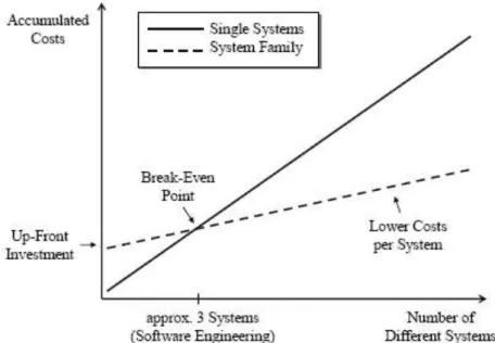
One of the most relevant purposes of an engineer is to create solutions that provide human benefices and economical profits. An essential reason for introducing product li ne engineering is the reduction of costs. When artefacts from the platform are reused in several different kinds of systems, and a standard work is implemented; this implies a cost reduction for each system. Before the artefacts can be reused, strategies investments and even a detailed planning are necessary for creating them. This means that the company has to make an up-front investment to create the platform before it can reduce the costs per product by reusing platform artefacts. Figure 1 -3-1 shows the accumulated costs needed to develop
n different systems. The solid line sketches the costs of developing the systems independently, while
the dashed line shows the costs for product line engineering. In the case of some few systems, the costs for product line engineering are relatively high, whereas they are significantly lower for larger quantities (one of the main microeconomics theories). The location at which both curves intersect marks the break-even point. At this point, the costs are the same for developing the systems separately as for developing them by product line engineering. Empirical investigations revealed that, for software, the break-even point is already reached around three systems.
A similar figure is shown in [Weiss and Lai 1999], where the break-even point is located between three and four systems. The precise location of the break -even point depends on various characteristics of the organisation and the market it has envisaged: the customer base, the expertise, and the range and kinds of products. The strategy that is used to initiate a product line also influences the break -even point significantly [McGregor et al. 2002].
Figure 1-2-1: Costs for developing n kinds of systems as single systems compared to product line
engineering
Enhancement of Quality
The artefacts in the platform must be reviewed and tested in many products and different processes. They have to prove their proper and correct functioning in more than one kind of product. The extensive quality assurance implies detecting faults, failures and improper work methods to correct them, thereby increasing the quality and reliability of all products.
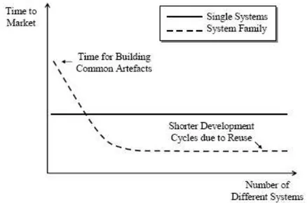
Reduction of Time to Market
Often, a very critical success factor for a product is not only the shelf life but when you begin w ith a project is time to launch it in the market. For single -product development, we assume it is roughly constant, mostly comprising the time to develop the product. For product line engineering, the time to market indeed is initially higher, as the commo n artefacts have to be planned and built first. Yet, after having passed this hurdle, the time to market is considerably shortened as many artefacts can be reused for each new product (see Figure 1 -3-2).
Figure 1-2-2: Time to market with and without product line engineering 1.2.2 The PLE process
As shown in Figure 1-2-3, the PLE process is split along this line into two sub processes: domain engineering and application engineering [Pohl et al. 05].
Domain Engineering
The principle of PLE is to exploit common elements of a number of different systems by developing them as one single core while still allowing differences between these systems. Commonalities, i.e. functions or properties that systems of the future product line have in common [Coplien et al. 98], and differences (generally called variabilities [van Gurp et al. 01]), however, have to be defined into the PL model during this sub-process.
The domain engineering process is the process in which the scope is decided. Based on this scope, the commonalities and differences of systems in the PL are defined.
Application Engineering
This process is based on the Domain Engineering once commonalities have been exploited and implemented as reusable artefacts and variability have been defined as variation points. The application engineering process now exploits this variability to apply it at the correct moment of the process.
Each variation point is analysed and one of its variants chos en (we can say that the variation point is bound). Once all variation points are bound to variants, a particular s ystem of the PL is initiated. The reusable artefacts will be then assembled and after successful integration tests, the development of the new products is finished.
1.2.3 Commonality and Variability
To facilitate mass customisation, the artefacts used in different products have to be sufficiently adaptable and flexible to fit into the different systems produced in the product line. This means that throughout the development process we have to identify and describe where the products of the product line may differ in terms of features that they provide, the requirements they fulfil, or even in terms of th e underlying architecture, etc. Thus we have to provide flexibility in all those artefacts to support mass customisation.
A very well known case is that of the different cars of the same product line which may have different windshield wipers and washers. Ingeneers design cars in a way that allows a common approach to support the different motors for these different windshield wipers/washers, their different sizes, etc. Such flexibility comes with a set of constraints. If you drive a convertible, you do not want a rear window washer splashing water onto the seats! Therefore, the selection of a convertible car means the flexibility
that the availability of the windshield wipers and washers is restricted, so that the rear window washer is disabled when the car roof is open.
This flexibility is a precondition for mass customisation; it also means that we can predefine what possible realisations shall be developed (there are only a certain number of windshield wiper configurations conceivable). In addition, it means that we define exactly the places wh ere the products can differ so that they can have as much in common as possible. The flexibility described here is called "variability" in the product line context. This variability is the basis for mass customisation.
1.3 Product Line Models
Product line models or product line diagrams are commonly used to define the valid combinations of elements in a product line. Not all elements are compatible.
There are two types of requirements specifications [Faulk 01] in product line engineering : The product line (or domain) requirements specification and the product (or application) requirements specification. The Product Line Requirements Specification (PLRS) or Product Line Model (PLM) as we will refer to this concept in the rest of document is developed during domain engineering. It contains all the common and variable requirements of all products of the product line. Requirements specification of a particular product of the product line is commonly named Product Requirements Specification (PRS) or Product Line Configuration (PLC), we will use the latest in the rest of document. The PRS for a particular product is derived from the PML [Pohl et al. 05], [Bühne et al. 06].
When deriving a PLC, all common requirements defined in the PLM become part of each PLC. The variable requirements can be added to a PLC by selecting variants from the variability model and thereby adding the variable requirements related to the selected variants. We can not only make a derivation, we also can create an independent configuration, and then contrasting it with its product line model. Another existing relation between both can be to try to deduce PLM from a set of PLCs.
Product line model notations
The Feature Diagram (FD) notation used in Figure 1-4-1 is built based on the FORE formalism. FORE (Family Oriented Requirements Engineering) [Streitferdt 03] is a method proposed by Riebisch and his work group at Alexandria project [Alexandria]. We have chosen this formalism because it offers all of the modeling facilities of previous notations to its launching. Besides, it includes some of the characteristics and construction rules particularly important at the moment of implementing the method proposed in this work. For example, FORE introduce the use of cardinalities [Riebisch et al. 02], enriching feature
diagrams with UML cardinalities. Also, FORE proposes that all variant features grouped with relations of cardinalities be optional features.
Some of the properties that characterise FORE notation are: A feature diagram is a Directed Acyclic Graph (DAG) A feature is a node of this graph
Relationships between features are represented by links. There are two types of relationship, variant dependency and transverse dependency.
Variant dependencies can be of kind mandatory or optional. The sense of relations is determined by a white or black circle at the end of the line. Black circle represents a mandatory relationship between father and child features, that is, if father is chosen, then child feature must be selected too. White circle represents an optional relationship between father and child features, which is, if father is chosen, child can or can not be selected.
Transverse dependency can be of two kinds: an exclude relation or a require relation. An exclude relation is represented by a two headed arrow ( ) and a require relation is represented by one headed arrow ( ). The direction of relations is determined by an arrow at the end of a dotted line.
Optional relations with the same father can be grouped in a set. A relation can be member of one and only one set.
A set have a cardinality that indicates the minimal and maximal number of features than it is possible to choice. The set of possible values is: 0.1, 1, 0.N, 1.N, N, p, 0.p, 1.p, p.N, m..p, 0..* and 1..*.
Graphically, the set of features grouped by a transverse dependency relationship is represented by a line or arch comprising all the implicated relations and a couple of symbols as shown in the previous numeral.
Grey rectangles are destined to represent features that have as function to facilitate the structure of the model [Streitferdt 03].
Although this notation seems adequate to construct models of product lines by means of features and that eliminates most of the ambiguities, the notation FORE does not, nor its predecessor FODA, establish utilization rules to guide the engineer in the modelling process. It does not establish either any rule permitting to identify a big of ambiguities that exit even in this type of models. Th ose ambiguities will be treated with detail in chapters III, IV and VI .
Another notation is VFD (varied feature diagrams) introduced by Schobbens et al. in [Schobbens et al. 06]. This one is just another notation among several other new or adapted FD notations that have been proposed since the original introduction of FDs as part of the FODA method [Kang et al. 90]. Other extensions of FODA are the following: FORM, an extension of FODA [Kang et al. 98]. FeatuRSEB [Griss et al. 98], an integration of FODA and the Reuse-Driven Software Engineering Business (RSEB) [Jacobson et al. 97] are two more propositions based on features. Van Gurp et al. extend FeatuRSEB to include binding times [Van Gurp et al. 01]. Riebisch et al. replaced operator nodes by more general cardinalities [Riebisch et al. 02]. Batory introduces propositional constraints defined among features [Batory 05]. Czarnecki suggest cardinalities and provide a formalisation for these diagrams [Czarnecki
et al. 05]. PLUSS [Eriksson et al. 05] is another extension of FeatuRSEB. All the above mentioned
notations are only a subset of all existing FD notations.
At the moment, there is no unified and universally accepted notation.
However, most of the notations cited above can be defined using a general parameterised FD definition, as proposed in section 1.3.2.
1.3.1 Feature Diagrams
Feature diagrams (FDs) are used to model and manage variability of a PL. FDs capture commonalities and variabilities by structuring the represented information in the form of a feature tree, or a directed acyclic graph (DAG). The tree or the DAG represents the decomposition of one feature into an arbitrary number of sub-features. The root feature is called concept and represents the system itself.
A FD is a hierarchical decomposition of the system into features and subfeatures. This hierarchy can be either a tree or DAG, which allows a feature to have more than one parent node. This structure is supported by FORE formalism, in opposition to FODA notation that is limited to trees. Most authors who extended the tree structure to a DAG argued for more expressiveness.
1.3.2 Formal semantic
In literature we have found several formal definitions of feature models [Czarnecki, Pietroszek 06], [Metzger et al. 07]. These formal definitions have not adapted to our verification process based in evaluations of logical rules in order to check both static and dynamic properties of product line models and not only product line configurations.
For us, a Feature Diagram d (based in the FD metamodel that we will present in next sections) is a eight-tuple (F, r, VD, AVD, TD, ATD, A, C) where:
F is the set of features
r F is the root of d, r is unique |r| = 1
VD F X F is the set of variant depen dencies edges,
AVD is an application of VD set at { , }, representing optional dependency and representing mandatory dependency. (f, f’) VD will rather be noted f f’ for optional relations and f f’ for mandatory relations, where f is the child and f’ is the father
TD F X F is the set of transverse dependency edges
ATD is an application of TD set at { , }, representing require dependency and representing
exclude dependency. (f, f’) TD will rather be noted f f’ for include relations and f f’ for exclude relations
A n
AVD
is a finite set of arcs, each couple of variant dependencies participating in A must be an optional dependency.
C is an application of arcs set at (NXN
*)that define the cardinality of AFor the variant dependency v = (f, f’), with f, f’ in F, the node f is so-called father of v and the node f’ is so-called child of v. ) ( ) ( : ) , )( ( : 6 4 2 2 4 1 f f TD td f f TD td Examples j i f f TD TD by defined is n applicatio ATD The j i
0,2 ( , ) : * : 3 2 1 A f f a Example AVD A C by defined is n applicatio y cardinalit The n Example 1-3-1:
The follow is the graphic representation of Feature Diagram d = (F, r, VD, AVD, TD, ATD, A, C) defined by: F = { f1, f2, f3, f4, F5, F6 }; r = { f1 }; VD = { (f2 f1), (f3 f1), (f4 f1), (f5 f2), (f6 f2) }; TD= { (f4 f2), (f4 f6) }; A = { [0,2] (f2,f3) },
Figure 1-3-1: example of product line model in FORE notation. 1.4 Automated Analysis of Feature Models
The automated analyses of FMs is usually performed in two steps: i) The FM is translated into a certain logic representation ii) Off-the-shelf solvers are used to extract information from the result of the previous translation such as the number of possible products of the feature model, all t he products following a criterion, finding the minimum cost configuration, etc [Benavides et al. 06].
According to [Benavides et al. 07], the current implementation of the framework integrates three of the most commonly used logic representations proposed for the automated analyses of feature models: CSP, SAT and BDD. A complete performance test of solvers dealing with such representations and details about the translation of an FM into a CSP, SAT and BDD were introduced in [Benavides et al. 06b], [Benavides, Ruiz 05].
F2
F3
F4
F1
F5
F6
0,2Three of the most commonly used logic representations proposed for the automated analyses of feature models: CSP, SAT and BDD.
Constraint Satisfaction Problem (CSP)
A Constraint Satisfaction Problem (CSP) [Tsang 95] consists on a set of finite domains variables, and a set of constraints restricting the values of the variables. Constraint Programming can be defined as the set of techniques such as algorithms or heuristics that deal with CSPs and the purpose is to find combinations of values in which all constraints are satisfied based on a common objective. The main ideas concerning the use of constraint programming on FM analysis were stat ed in [Benavides et al. 05].
Constraint Programming is the most flexible proposal. It can be used to perform the most of the operations currently identified on feature models [Benavides et al. 06a]. However, constraint programming solvers reveal a weak time performance when executing certain operations on medium and large size feature models calculating the number of possible combinations of features due most of the time to a high number of variables [Benavides et al. 06c].
Boolean Satisfiability Problem (SAT)
A propositional formula is an expression consisting on a set of boolean variables (literals) connected by logic operators (¬,^,v, , ). The propositional satisfiability problem (SAT) [Cook 71] consists on deciding whether a given propositional formula is satisfiable, i.e., a logical values can be assigned to its variables in a way that makes the formula true. The basic concepts about the using of SAT in the automated analysis of FMs were introduced in [Batory 05].
The performance results of SAT solvers are slightly better than the results of CSPs . however this approach is not so powerful [Benavides et al. 06c]. The best of our knowledge, it is that there is not any approach in which feature models attributes c an be translated to SAT in order to perform operations as maximizing or minimizing attribute values.
Binary Decision Diagrams (BDD)
A Binary Decision Diagram (BDD) [Bryant 86] is a data structure used to represent a boolean function. A BDD is a rooted, directed, acyclic graph composed by a group of decision nodes and two terminal nodes called 0-terminal and 1-terminal. Each node in the graph represents a variable in a Boolean function and has two children nodes representing an assignment of the variable to 0 and 1. All paths from the root to the 1-terminal represents the variable assignments for which the represented Boolean
function is true meanwhile all paths to the 0 -terminal represents the variable assignments for which the represented Boolean function is false.
Although the size of BDDs can be reduced according to some established rules, the weakness of this kind of representation is the size of the data structure which may vary between a linear to an exponential range depending on the variable ordering [Bryant 86]. Calculating the best variable ordering is an NP-hard problem. However, the memory problem is clearly compensated by the time performance results offered by BDD solvers. While CSP and SAT solver are incapable of finding the total number of solutions of medium and large size feature models in a reasonable time, BDD solvers can work it out in an insignificant amount of time, so it justifies its usage at least on counting operations.
1.5 Conclusion
The objective of this first chapter was to survey different RE and product line relevant definitions to our work. This includes not only notations found in literature, but also owned definitions necessaries for our approach such as a formal semantic of a PLM. These definitions will be used in the rest of this document. In this chapter we also highlight the importance of product line engi neering for the industry and its relation with RE.
The next chapter presents the problematic situation that has motivated this research work and the way that we have used to tackle it.
Part II
2. Research problem, methodology and justification.
2.1 Research problem
We have observed that the few solutions developed over the past ten years have not been integrated into a coherent and flexible process of V&V. The penury of methods for the formal verification of conceptual models and the urgency of proposing well adapted approaches are recognized by the scientific community [Wang et al. 05], [Polh et al. 05], [Lauenroth, Pohl 07]. Likewise, the lack of tools for the industry was cited in the Fourth Product Line Engineering Workshop acts [Bass et al. 99], in 2001 by Zave [Zave, 01] and again recently by Padmanabhan and Lutz [Padmanabhan, Lutz 05]. The recent award of Turing Prize '07 by Joseph Sifakis for his work in model checking confirms the importance of this topic, and the importance to continue its exploration.
2.2 Research methodology
The methodology followed in this investigation can be summarized in following steps: 1. Bibliographic search that permit us make an inventory of some techniques
2. Formalisation work of each criterion, particularly those for PLM verification, with propositional and first order logic notations [Bradley, Manna 07].
3. Integration work through MAP formalism, in order to propose a PLM correctness verification process that can be carried out of different ways .
4. Approach validation through a real case study and implementation of the proposed MAP process model in a computational tool.
3.3 Justification
Graphical representation of PLMs can be directly represented in logical constraints that can be evaluated by means of SAT solvers or constraint scheduling. MAP is a formalism that allow s representing multi-process. That is, a MAP representation is not a sequence predefined of tasks. It is rather a set of tasks that may be organized in a different way, in terms of situation and intention of the person using the map.
We have used propositional logic and first order logic in order to represent the set of invar iant or logic rules that must respect a PLM. Propositional logic and first order logic are also known as propositional calculus and predicate calculus, respectively, because they are calculi for reasoning about propositions (“the sky is blue”, “this comment references itself”) and predicates (“x is blue”, “y references z”), respectively. Propositions are either true or false, while predicates evaluate to true or false depending on the values given to their parameters (x, y, and z). And to represent the process we have used MAP formalism. Loosely speaking, a Map [Rolland et al. 99] is a navigational structure in the form of a graph where nodes are intentions and edges are strategies. It is possible to follow different strategies for each couple of target/source intentions, thus dynamically determining different solution paths between start and end. So a Map is a modelling formalism that permits to represent several processes on the same design.
Part III
3. State-of-the-art on Validation and Verification in Requirements Engineering
3.1 Definition of Verification
Formal verification is the process of checking whether a design satisfies some requirements ( called properties or invariants in this document).
Verification work typically proceeds as follows [Bjorner 06]: “Desired properties of the requirement’s model, properties that do not transpire immediately from the proofs by symbolic testing or formal proofs, or model checking, is, or are, performed in order to check that the desired property(ies) holds of the requirements model”.
3.2 Definition of Validation
By requirements validation we shall understand a process with some resulting documents in which some requirements’ prescriptive artefacts (documents, models, etc.) are being inspected by both requirements’ stakeholders and requirements’ engineers. This includes the pointing in, the pointing out, if necessary, of inconsistencies, incompletenesses, conflicts and errors of prescription that may change the elicitation report.
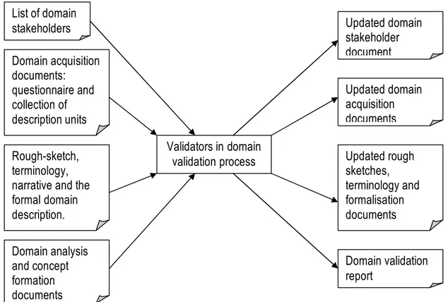
According to [Bjorner 06], in order to perform domain validation, the validators need the following (input) documents: (i) the list of domain stakeholders; (ii) the domain acquisition documents: questionnaire, and the collection of indexed description units; (iii) the rough-sketch, terminology, narrative, and possibly the formalisation documents that constitute the domain description proper; and (iv) the domain analysis and concept formation documents. That is, the validators need access to basically all documents produced in the domain modelling effort. In order to complete domain validation, the validators produce the following output documents: (i) A possibly updated domain stakeholder document; (ii) Possible updated domain acquisition documents, (iii) P ossible updated rough sketches, terminology, narrative and the formalisation documents; and (iv) A domain validation report. We now cover some aspects of the necessarily informal validation process.
Figure 3-2-1: Domain validation input and output documents
Validation works typically proceeds as follows [Bjorner 06]: requirements engineers, requirements stakeholders and review, line by line, the domain model, holding it up against the previously elicited requirement prescriptions’ units, while then noting down any discrepancies.
In doing requirements’ validation, requirements’ stakeholders usually read the informal, yet precise and detailed narrative prescriptions. No assumption is made as to their ability to read formalisations. On the contrary, it is assumed that they cannot read formal specifications.
3.3 Verification vs. Validation
The following authors give their point of view concerning the difference between verification and validation:
According to Boehm, in verification we examine whether our requirements model is logic or according to such requirements engineers want it to be, “Verification gets the requirements model right” [Boehm 81]. In validation we examine the requirements’ model to make sure we are modelling what the
List of domain stakeholders Domain acquisition documents: questionnaire and collection of description units Rough-sketch, terminology, narrative and the formal domain description. Validators in domain validation process Updated domain stakeholder document Updated domain acquisition documents Updated rough sketches, terminology and formalisation documents Domain validation report Domain analysis and concept formation documents
requirements’ stakeholders think that the domain is, “Validation gets the right requirements model”. Usually verification precedes validation.
According to Kuloor and Eberlein, “Requirements are verified to check their completeness, precision and suitability in the requirements verification stage [Kuloor, Eberlein 02]. Formal reviews, prototyping and requirements testing are some of the techniques used for requirements verification. A product family has more than one product and most of the requirement s are common across the family”.
Ponsard et al., suggests that “verification is about making sure the system is correct, especially with respect to formal semantics of the goal model. Validation is about making sure the system being built is the system the user is expecting” [Ponsard et al. 05].
Verification:
A set of goals G1, ... , Gn refines a goal G in a domain theory D if the following conditions holds:
G D G G G ss Completene : 1, 2,..., n,
n
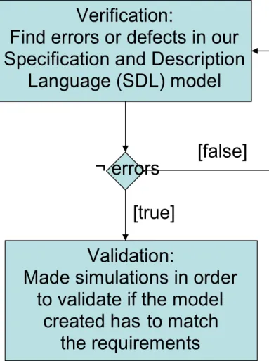
i G D G Minimality:ji j, 1,2,..., false D G G G y Consistenc : 1, 2,..., n, In [Probert et al. 2003] authors claim that to verify a model is to make sure that it is created correctly, which means there is no defect or error present. Examples include deadlocks, live -locks, and implicit (missing) definitions in the model that are introduced via the design process itself.
“To validate a model is to make sure we create the right model, which means the model created has to match the requirements. Simulation involves making an executable program based on a system specification and running this executable progr am to understand and debug the behavi our of the system specification”.
Figure 3-3-1: Relationship between verification and validation proposed by Probert et al.
According to [Bahill, Henderson 2005], verifying requirements is the process aiming to proving that each requirement has been satisfied. Verification can be done by logical argument, inspection, modelling, simulation, analysis, expert review, test or demonstration. Bahill and Henderson also define validating requirements as the process to ensure that the set of requirements is correct, complete, and consistent; a model can be created to satisfy the requirements; a real-world solution can be built and tested to prove that it satisfies the requirements.
Otherwise, Easterbrook holds that the terms Verification and Validation are commonly used in software engineering to mean two different types of analysis [Easterbrook 96]. The usual definitions are:
Verification: Are we building the system correctly? Validation: Are we building the correct system?
Requirements’ verification and validation ends up with a report which either accepts the requirements ’ model, or points out needs to correct the elicitation report, the requirements analysis and concept
Verification:
Find errors or defects in our
Specification and Description
Language (SDL) model
Validation:
Made simulations in order
to validate if the model
created has to match
the requirements
¬ errors
[false]
Thus requirements verification and validation can be expected to be an interactive process alternating with further requirements elicitation report work, possibly with further requirements analysis and concept formation work; and ending with further requirements verification and validation work.
In the following section we will split the characteristics found in the literature which we consider relevant to evaluate in an RS document. Two groups will be created, based on the criterion described above verification / validation. Some characteristics should be verified and validated to ensure a complete evaluation.
In the rest of the document we will assume verification and validation as two complementary processes. We will consider verification as the first step of the validation process. In this sense, the fundamental strategy of verification is to identify and to reduce errors in a model, that is, verification deals with mathematics. And validation addresses the question of the f idelity of the model to specific conditions of the real world, that is, v alidation deals with requirements.
3.4 Desirable characteristics to verify
In general, the most important elements to respect in order to guarantee an acceptable requirement specification quality level are defined in [Lami 2007] and can be resumed in the next fourth tables:
Indicator Description
Vagueness When parts of the sentence are inherently vague (e.g., contain words with non -unique quantifiable meanings). For example: easy, strong, good, bad, useful, significa nt, adequate and recent.
Subjectivity When sentences contain words used to express personal opinions or feelings. For example: similar, similarly, having in mind, take into account and as [adjective] as possible
Optionality When the sentence contains an optional part ( a part that can or cannot be considered). For example: possibly, eventually, in case of, if possible, if appropriate, if needed
adjectives (e.g., this, these, that, those) or pronouns (e.g., it, they). Implicit adjective (e.g., previous, next, following, last), or preposition (e.g., above, below).
Weakness When a sentence contains a weak verb. For example: could, might and may.
Table 3-4-1: Ambiguity Indicators for RE’s verification and validation
Indicator Description
Multiplicity When a sentence has more than one main verb or more than one subject.
Readability The readability of sentences is measured by the Coleman-Liau Formula of readability. The reference value of this formula for an easy -to-read technical document is 10. If the value is greater than 15, the document is difficult to read.
Table 3-4-2: Understandability Indicators for RE’s verification and validation
Indicator Description
Under-specification
When a sentence contains a word identifying a class of objects without a modifier specifying an instance of this class.
Table 3-4-3: Completion Indicators for RE’s verification and validation
Indicator Description
Vagueness See Table 3-4-1
Subjectivity See Table 3-4-1 Optionality See Table 3-4-1
Implicity See Table 3-4-1
Weakness See Table 3-4-1
Under-specification
The use of words that need to be instantiated (i.e., access [write, remot e, authorized access]
Multiplicity The use of multiple subjects, objects, or verbs, which suggests there are actually multiple requirements.
Numerous definitions exist in literature for requirements’ quality concepts likely to be verified, as a result of environmental specialization, variety of purpose, granularity level, etc. The following are some of the characteristics that must be verified in a n RS document or model.
3.4.1 Completeness
A requirement model specification is completed if f ull labels and references to all figures, tables, diagrams, definitions of all terms and units of measure are included in the RS document. According to [Bjorner 06] a requirements’ model is completed if no holes can be pointed out, that is, everything needed to be prescribed has been prescribed. Completeness is thus relative. It is only written what “needs” be described, not what “can” be described.
According to [Zowghi, Gervasi 03], a measure for the “degree of completeness” of a set S subject to R D, we consider the ratio between the size of a maximal subset of S that is entailed by R D (maximal entailed subset, or mes) and the size of the whole set S, i.e.:
S S D R mes S D R compl ) , ( ) , , (
This measure, too, has value 1 when completeness holds, and assumes progressively lower values, down to 1, for decreasing completeness.
3.4.2 Consistency of the requirements model
Zowghi and Gervasi claim that consistency requires the inexistency of two or more requirements in a specification contradicting each other [Zowghi, Gervasi 03].
As a measure for the “degree of consistency” we consider the ratio between the size of a maximal consistent subset (mcs) of R D and the size of the whole set, i.e.:
D R D R msc D R cons ( ) ) , (
For consistent R and D, cons (R;D) = 1, whereas the measure tends to 0 the inconsistency degree
increases.
A wide variety of possible causes of inconsistency in software development have been identified in the research literature. For example, in [Nuseibeh 96], the author views inconsistency as it arises between the views of multiple stakeholders in software development. In addition, Easterbrook [Easterbrook et al. 95] regard an inconsistency similarly as any situation in which two parts of a specification do not obey some relationship that should be hold between them. Something similar proposes Bjorner [Bjorner 06], who claims that inconsistency of a requirements prescription is referred to some pairs (or more) of text where one text prescribes one (set of) property (properties), while another text (of the pair or more) prescribes (prescribe) an “opposite” property (set of properties), th at is: Property P and Property not P.
In [Lamsweerde et al. 98]it is possible to find most current techniques for inconsistency handling in the current literature consider binary -relation conflicts only.
There are potentially many ways to resolve inconsistencies [Balzer 91]. Consistency in requirements models thus implies a lack of contradiction within the presented information. Both a direct refutation of previously stated requirement and an indirect denial of this description can constitute contradicti ons within the requirements’ model. Direct refutation represents statements within the model that are incompatible with each other. The truth of the first statement of a requirement directly negates the truth of the second statement. Moreover, information within the model can be refuted in an indirect manner. A given set of facts could establish a potential situation that, given the proper set of circumstances, would contradict other facts within the model. In practice whether a statement is an implicit con sequence is a matter of degree. Therefore, establishing consistency within a requirements ’ model is primarily a semantic task.
3.4.3 Correctness
Correctness in specification requirements is verified by checking both, consistency and completeness [Zowghi, Gervasi 03].
Figure 3-4-1: Relationship between Specification, Domain and Requirement in an evolutionary
framework.
In figure 3-4-1, arrows represent evolution steps between successive versions of requirements and domain descriptions.
Several revisions of the requirements are considered, each one serving the role of a specification with respect to the previous one. This situation may be found in practice when we consider the common case of a product family undergoing several release cycles, but also, at a finer grain, inside a single release cycle.
Monotonic domain refinement: if we are performing an evolution step, from Ri and Di to the
subsequent versions Ri+1 and Di+1, and we are only adding new information about the domain, i.e. Di+1 j= Di. Then,
i i i i Ri t r w ss completene i i i y consistenc i i D R D R R D R D R ) ( ) ( ) ( 1 1 . . . 1 1 1 1
That is, if we can prove that:
Consistency: our new requirements are consistent with the domain (i.e., they are not asking for
something that is impossible in the real world), and that Completeness w.r.t. Ri: the new requirements and domain description, together, do not contradict the previous requirements, then (Ri+1 U Di+1) |= Ri U Di holds.
Monotonic requirements refinement: if we are performing an evolution step, from Ri and Di to the
subsequent versions Ri+1 and Di+1, and we are only adding new requirements, i.e. Ri+1 |= Ri. Then,
i i i i Di t r w ss completene i i i y consistenc i i D R D D R D R D R ) ( )( ) ( 1 1 . . . 1 1 1 1
In other words, if we can prove that:
Consistency: our new requirements are consistent with the domain described so far, and that Completeness w.r.t. Di: the new requirements and domain description, together, do not contradict the
previous domain description, then (Ri+1 U Di+1) |= Ri U Di holds. Where Ri: requirement specification i, Di: domain specification i.
3.4.4 Satisfiability, faithful or constraint consistency
According to [Zhang et al. 04], in a product line modelling process, satisfiability ensures that there is no inconsistency in tailoring and binding actions at the moment of deriving a particular product line configuration form the product line model. If this pr operty is not satisfied, constraints on features or those tailoring and binding actions should be reconsidered to eliminate inconsistencies. This definition is not implemented by means of a computational tool and the level of operationalisation and formali sation is not developed. Zhang et al. propose a logical formula in order to automate the satisfiability verification process, but their implementation into a compu ting application is not yet done .
3.4.5 Suitability of each RS model element
Within the framework of software development, ISO/IEC 2001 defines suitability as the presence and appropriateness of a set of functions for specified tasks . And in the context of product line modelling, [Zhang et al. 04] claim that suitability ensures that every feature without being selected has the possibility of being removed at any time. If this property is not sa tisfied, it means that there is one or more features that will not have the chances to be removed at some moments of its life cycle. That is to say, these features actually have been bound. Zhang et al. say that possible causes may be that the operators have ignored the binding of these features, or have done some improper tailoring or binding actions, or some constraints themselves are wrong. Zhang et al. propose a logical formula in order to automate the suitability verification process, but their implementation into a compu ting application is not yet done.
3.4.6 Usability of each RS model element
According to [Zhang et al. 04] usability ensures that every feature in the product line model has the possibility of being added at any time . They hold also that if the property is not satisfied, it means that there is one or more features that will not have the chances to be bound after the current binding time . That is to say, these features actually have been removed from the feature model. The possible causes may be that the operators have ignored the tailoring actions on these features, or have done some improper tailoring or binding actions, or some constra ints themselves are wrong. They propose to eliminate these causes by putting these features to removed feature s ets, or by undoing some actions at the current binding time, or by revising constraint s on features. Zhang et al. propose a logical formula in
order to automate the usability verification process, but their implementation into a computing application is not yet done.
3.4.7 Verifiability of the RS model
In [IEEE 98] and [IEEE 04] we find that an RS is verifiable if, and only if, every requirement stated therein is verifiable. A requirement is verifiable if, and only if, there exists some fi nite cost effective process in which a person or machine can check that the software product meets the requirement. In general any ambiguous requirement is not verifiable.
According to Bjorner, this criterion relates to the implementation stage. For a requirement to have been met by an implementation means that it can be proven or tested [Bjorner 06]. Some requirements can not be so tested, at least not objectively and not quantifiable. In the case of product line, we think that all models can be verified and t his premise has been the one that has motivated this research work.
3.5 Desirable characteristics to validate
There are numerous definitions in the lite rature for requirements quality concepts to validate, as a result of environmental specialization, variety of purpose, granularity level, etc. The following are some of the desirable characteristics that must be validated in a RS document or model.
3.5.1 Completeness
According to Boehm, to be considered complete, the requirements’ document must respect three fundamental characteristics [Boehm 84]:
a) To include all significant requirements, whether relating to functionality, performance, design constraints, attributes, or external interfaces. In particular any external requirements imposed by a system specification should be acknowledged and treated.
b) To include definition of the responses of the software to all realizable classes of input data in all realizable classes of situations. Note that it is important to specify the responses to both valid and invalid input values.
c) To include full labels and references to all figures, tables, and diagrams in the RS and definition of all terms and units of mea sure.
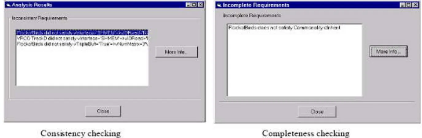
![Figure 4-1-1: RACER detect an inconsistency, taken from [Wang et al. 05]](https://thumb-eu.123doks.com/thumbv2/123doknet/13123827.387655/52.892.132.663.102.655/figure-racer-detect-inconsistency-taken-wang-et-al.webp)

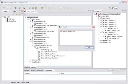
![Figure 4-1-14: multiple-view approach for modelling variability and consistency checking (taken from [Gomaa, Shin 04])](https://thumb-eu.123doks.com/thumbv2/123doknet/13123827.387655/63.892.138.649.146.509/figure-multiple-approach-modelling-variability-consistency-checking-gomaa.webp)
