HAL Id: hal-01951316
https://hal-amu.archives-ouvertes.fr/hal-01951316
Submitted on 11 Dec 2018
HAL is a multi-disciplinary open access
archive for the deposit and dissemination of
sci-entific research documents, whether they are
pub-lished or not. The documents may come from
teaching and research institutions in France or
abroad, or from public or private research centers.
L’archive ouverte pluridisciplinaire HAL, est
destinée au dépôt et à la diffusion de documents
scientifiques de niveau recherche, publiés ou non,
émanant des établissements d’enseignement et de
recherche français ou étrangers, des laboratoires
publics ou privés.
Distributed under a Creative Commons Attribution| 4.0 International License
To cite this version:
Anna Hurshkainen, Anton Nikulin, Elodie Georget, Benoît Larrat, Djamel Berrahou, et al.. A Novel
Metamaterial-Inspired RF-coil for Preclinical Dual-Nuclei MRI. Scientific Reports, Nature Publishing
Group, 2018, 8 (1), �10.1038/s41598-018-27327-y�. �hal-01951316�
A Novel Metamaterial-Inspired
RF-coil for Preclinical Dual-Nuclei
MRI
Anna Hurshkainen
1, Anton Nikulin
1, Elodie Georget
3,4, Benoit Larrat
3,4, Djamel Berrahou
2,
Ana Luisa Neves
2, Pierre Sabouroux
2, Stefan Enoch
2, Irina Melchakova
1, Pavel Belov
1,
Stanislav Glybovski
1& Redha Abdeddaim
2In this paper, we propose, design and test a new dual-nuclei RF-coil inspired by wire metamaterial structures. The coil operates as a result of resonant excitation of hybridized eigenmodes in multimode flat periodic structures comprising several coupled thin metal strips. It was shown that the field distribution of the coil (i.e. penetration depth) can be controlled independently at two different Larmor frequencies by selecting a proper eigenmode in each of two mutually orthogonal periodic structures. The proposed coil requires no lumped capacitors to be tuned and matched. In order to demonstrate the performance of the new design, an experimental preclinical coil for 19F/1H imaging of small animals
at 7.05T was engineered and tested on a homogeneous liquid phantom and in-vivo. The results demonstrate that the coil was both well tuned and matched at two Larmor frequencies and allowed image acquisition at both nuclei. In an in-vivo experiment, it was shown that without retuning the setup it was subsequently possible to obtain anatomical 1H images of a mouse under anesthesia with 19F
images of a tiny tube filled with a fluorine-containing liquid and attached to the body of the mouse.
Magnetic resonance provides unique instrumentation for modern biomedical studies. In clinical and preclinical applications, radiofrequency (RF) coils play an important role of antennas exciting spins in a subject under an applied strong static magnetic field with a desired flip angle and receiving weak echo signals at the Larmor fre-quency. Thus, a signal-to-noise (SNR) ratio of images, strongly dependent on electromagnetic properties of RF coils, becomes particularly important if a density of an investigated nucleus in the sample is low.
In multi-nuclei studies, it is possible to retrieve additional imaging and/or spectroscopy information using the magnetic resonance of several nuclei of interest typically taking place at different Larmor frequencies for the same magnet field B0. The Larmor frequency of a nucleus is determined by its gyromagnetic ratio γ as fL = γ·B0. The
corresponding RF-coils, suitable for multi-nuclei MRI, must operate at all desirable Larmor frequencies simulta-neously given that the input impedance is matched to the transceiver channel(s) and the RF-field distribution in a subject ensures maximum B+
1 per unit power efficiency in transmission over the region of interest. The
afore-mentioned properties also ensure a high SNR of the same coil in reception improving imaging quality and reso-lution of measured molecular spectra.
Preclinical studies impose additional limitations on RF-coil designs. The dedicated coils must be compati-ble with other equipment required for the biomedical experiment, such as excitation systems and sample beds. Another challenge comes from the electromagnetic environment of preclinical scanners, where RF-coils must operate inside an electrically narrow, shielded tunnel. Finally, RF-coils are typically very sensitive to variation of a subject’s electrical properties. In contrast to large coils (for instance, those used for clinical applications) where the noise from the subject dominates, in the so-called mid-range preclinical coils, the subject noise becomes comparable to the intrinsic noise of the coil1. This last fact results from power losses in the coil’s components and
strongly depends on the coil’s design and quality of its materials.
RF-coils for small-animal imaging and spectroscopy at the fields 3–17 T are typically volumetric coils which have linear polarization of the RF magnetic field such as solenoids providing high SNR if the sample losses are not
1Department of Nanophotonics and Metamaterials, ITMO University, 197101, St. Petersburg, Russia. 2Aix Marseille
University, CNRS, Centrale Marseille, Institut Fresnel, Marseille, France. 3Commissariat à L’Energie Atomique et
aux Energies Alternatives/Direction de la Recherche Fondamentale/Institut Joliot/Neurospin, 91191, Gif-sur-Yvette Cedex, France. 4Université Paris Saclay, Orsay, France. Correspondence and requests for materials should be
addressed to A.H. (email: a.hurshkainen@metalab.ifmo.ru) Received: 4 October 2017
Accepted: 24 May 2018 Published: xx xx xxxx
dominant1,2 or saddle coils3 as well as circular polarization coils such as ‘birdcages’4,5. The volume MR coil with
the enhanced SNR was shown in6 where the comprehensive design with the tuning stability to the sample
varia-tions and large homogeneity of B+
1 has been demonstrated. Surface coils implemented as planar/conformal
loops7–9 are also used in specific applications. Most conventional loop RF-coil designs have electrically small
dimensions. When excited by an RF-cable, they exhibit inductive input impedance and, therefore, need to be tuned and matched at the desired Larmor frequencies using matching circuits with multiple on-chip capacitors1.
Smaller coil and bore dimensions require higher capacitance for tuning and matching which is accompanied by increasing losses and reducing SNR with rising Larmor frequencies. SNR can be substantially enhanced by using cryogenic technology10 where the internal coil losses are eliminated by introducing the coil in superconductive
condition. Nevertheless, cryogenic coils are very expensive and are therefore not commonly used. Small-animal coils for scanning at two Larmor frequencies usually contain a tuning and matching circuit with at least two var-iable capacitors. A general dual-frequency matching strategy based on lumped capacitors has been proposed and validated in application to several different coils for the dual-nuclei 19F/1H imaging at 4.7 T11 (188 MHz and
200 MHz correspondingly). Lumped-element dual-frequency circuits have the advantage of providing similar RF-field patterns at both Larmor frequencies11. It has also been proposed12 that decoupled separate loops plugged
into two separate channels of a 4 T MR system for scanning at 1H and 23Na (170 MHz and 45 MHz respectively)
can be used. Tuning and matching of this coil at two desired Larmor frequencies is also obtained by means of variable capacitors.
In general, at least four independent parameters must be presented in the schematic to meet the tuning and matching conditions at two separate frequencies with no limitation of a quality factor. In practice, the capacitors of a circuit are controllable from outside a bore using long dielectric rotating fixtures. The capacitors introduce losses due to strong localization of an electric field which increases intrinsic noise. Consequently, the require-ments to their quality factors are very strong.
In this work we have proposed, studied and experimentally validated a novel dual-nuclei coil design for pre-clinical imaging. The proposed coil uses resonant excitation of eigenmodes in multimode metamaterial-inspired structures of periodic metal strips, which makes it resonant at two Larmor frequencies with no lumped capacitors (in ladder-network coils13,14 a similar operational principle is used). The coil was tuned and matched once prior
to measurements simply by adjusting its geometric parameters. Importantly, no lumped elements are required for operation of the coil. For the on-bench and MRI experiments we have manufactured the coil and tested it in
19F/1H imaging on a phantom and in-vivo with a small animal at 7.05 T, corresponding to the Larmor frequencies
of 282.6 and 300.1 MHz with gyromagnetic constants of the nuclei: γ(1H) = 42.58 MHz/T, γ(19F) = 40.05 MHz/T.
Results
The proposed dual-frequency RF-coil operates as a result of excitation of eigenmodes in two mutually orthogonal periodic arrays of parallel thin metal strips by an external non-resonant circular loop feed (in the absence of the wire resonators the resonance of the loop is well above 300 MHz) connected to a single coax cable. These two wire metamaterial-inspired resonators are referred to as the long-wire resonator (with strips parallel to the direction z of the static field B0 of the magnet) and the short-wire resonator (with transverse strips with respect to B0).
Excitation of eigenmodes is possible owing to inductive coupling of the loop feed to both resonators. The coil geometry with a subject inside a preclinical MRI bore is depicted in Fig. 1(a). The long-wire resonator consists of identical nearly half-wavelength at 300.1 MHz strips, while the short-wire resonator for 282.6 MHz is based on shortened, but capacitively loaded, strips which fit preclinical bore dimensions. The capacitive loads connecting the adjacent strips of the short-wire resonator are rectangular copper patches of the dimensions b × c printed on a common grounded dielectric substrate of the thickness t. Such capacitive loading presents at both ends of the shortened strips. The patches loading the strips of the short-wire resonator are shown in the inset of Fig. 1(a)
while their connection to two adjacent strips is illustrated in Fig. 1(c).
Eigenmodes of wire metamaterial-inspired resonators.
In order to demonstrate the RF-field patterns created separately by the long-wire and the short-wire metamaterial-inspired resonators of the coil at their reso-nant frequencies, we performed a numerical study of their eigenmodes. This resulted in two sets of resoreso-nant fre-quencies and two sets of RF magnetic field distributions. These electromagnetic properties are useful to describeFigure 1. Proposed dual-nuclei RF-coil, comprising loop feed and two wire metamaterial-inspired resonators,
with subject inside RF-shield of MRI (a); illustration of miniaturization principle for resonator of two metal wires: current distributions and equivalent circuits of resonators with two half-wavelength (b) and shortened (c) parallel wires.
the physical principles behind the operation of the proposed coil under realistic MRI conditions. Instead of one electric-dipole-mode resonance of a single wire, in the array of N half-wavelength wires (the long-wire resonator) due to the inter-wire coupling, one can excite N = 6 eigenmodes with different resonant frequencies (the so-called hybridization effect). Each eigenmode has its individual RF-field pattern created by a unique combination of currents flowing in positive or negative directions along the strips. Despite the fact that all currents related to a certain eigenmode have different magnitudes and phases (0 or π in the lossless case), their distribution along each strip is similar and cosinusoidal (like at the resonance of a single wire).
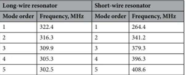
The numerically calculated resonant frequencies of the studied modes are listed in Table 1. In Fig. 2(c,e,g,i,k), the calculated normalized distributions of the Hy field component (normal to the plane of strips) are presented
for five of the six available eigenmodes of the long-wire resonator suitable for preclinical MRI applications. Figure 2(a) illustrates the geometric parameters of the resonator. The field is shown in the plane parallel to the resonator, 5 mm away from the plane of strips.
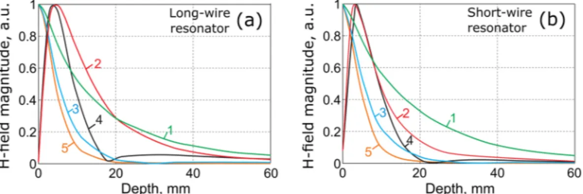
Similar results, calculated for the resonator composed of N = 6 shortened strips paired by connection through structural capacities (the short-wire resonator), are presented in the right column of Fig. 2. The short-wire reso-nator also supports six different eigenmodes, five of which are depicted in Fig. 2(d,f,h,j,l). Figure 2(b) shows the geometric properties of the short-wire resonator. Transverse plane eigenmode H-field patterns are depicted in Fig. 3 both for the long-wire (a–e) and short-wire (f–j) resonators. In Fig. 4, the dependence of the normalized H-field magnitude as a function of the distance away from the plane of strips (the depth) is illustrated for the long-wire resonator (a) and for the short-wire resonator (b). The observation point in each case is located in front of the center of the resonator.
Design and simulation of RF-coil.
The proposed dual-nuclei RF-coil as a whole combines the long-wire and the short-wire resonators studied in the previous subsection into the same design. Strips of the two res-onators are positioned in two parallel planes as shown in Fig. 1(a). The third parallel plane contains a feeding non-resonant circular loop which is inductively coupled to both resonators and is connected by a single coaxial cable to the transceiver at both Larmor frequencies. The main tuning parameters are the lengths L1 and L2 ofstrips, while the disposition of the loop feed with respect to the resonators is mostly responsible for matching. In the experimental antenna described in this work, these geometric properties were at once chosen and fixed for the specific sample. The sensitivity of the coil with respect to the sample variation was numerically studied by varying the sample size. In principle, the lengths of wires and the feed position could be made mechanically adjustable for compensation of significant subject variations, e.g. by using telescopic extendable tubes or worm screws.
Selection of a proper eigenmode at each Larmor frequency allows for control of the penetration depth. We performed a full-wave numerical simulation of the assembled coil in the presence of a phantom (the equivalent of a scanned subject) and the MRI tunnel. In order to demonstrate that the desired eigenmodes can be selected and adopted for operation of our coil at the given nuclei, we tuned Mode 3 of the long-wire resonator (see Fig. 2(g)) to the Larmor frequency of 1H and Mode 1 of the short-wire resonator (see Fig. 2(d)) to the Larmor frequency
of 19F. Due to the symmetry of their H-field distributions, both of these modes can be coupled to the circular
loop located over the center of both resonators. Figure 5(a) shows the simulated reflection coefficient (red dotted curve) from the feeding point of the RF-coil in the split of the loop with respect to 50 Ohm cable impedance. On the phase of numerical simulation, we also analyzed the proposed coil’s sensitivity to subject variation. In par-ticular, S11 of the coil around both Larmor frequencies was calculated with parametrically swept dimensions of
the cylindrical phantom (keeping the same phantom material properties). In the calculations, three values of the phantom radius: 0.8R, R and 1.2R, as well as three values of the phantom length 0.8L, L and 1.2L were considered, where R and L are the original parameters of the numerically optimized design. In Fig. 5(b,c) the calculated S11
vs. frequency plots are compared.
As can be observed from the loading sensitivity study results, once the coil is tuned and matched by adjusting geometrical parameters of its structure (wire lengths and the loop-to-resonator gaps), the S11 stays stable enough
when the phantom dimensions vary by ±20%. Therefore, the coil may be used without additional tuning and matching prior to each measurement when samples of the same type are investigated (e.g. mice of a similar kind). It was noted that when replacing a liquid cylindrical phantom by a living mouse, the coil had to be tuned and matched because two such different samples caused a larger loading variation than that caused by changing to a sample of the same type. This was done by adjusting the lengths of printed wires of the PCBs and by changing the gaps between the loop and the two resonators.
The calculated normal magnetic field component distributions created by the RF-coil are shown for 19F and 1H
Larmor frequencies in Fig. 6(a) and (c) respectively. Both observation planes were chosen 5 mm away from the planes of the resonating strips. Figure 6(b,d) presents the distributions of the right-handed circularly polarized
Long-wire resonator Short-wire resonator Mode order Frequency, MHz Mode order Frequency, MHz
1 322.4 1 264.4 2 316.3 2 341.2 3 309.9 3 379.3 4 305.3 4 396.3 5 302.5 5 408.6
component B+
1 at 19F and 1H Larmor frequencies respectively, which is responsible for the excitation of spins. B1+
is plotted in the central transverse plane of the MRI bore and the field values correspond to the accepted power of 0.5 W.
To demonstrate that another combination of eigenmodes can be selected for the same application, the other wire lengths and gaps between the loop and the wire resonators were numerically determined. As a result, it was shown that in both resonators Mode 1 can be excited, which is observed in Fig. 6(e,j). This combination provides the highest penetration of fields at both Larmor frequencies (compare Fig. 6(d) for Mode 3 and Fig. 6(h) for Mode 1 of the long-wire resonator). However, compared to the previous combination where the different modes were selected for the two resonators, similar modes cause stronger coupling between the resonators. This results in
Figure 2. Geometry and eigenmode H-field patterns (normal component with respect to plane of strips), in
higher distortion of the field pattern depicted in Fig. 6(e,j) as compared to the corresponding eigenmode patterns (see Fig. 2(c,d)).
MRI experiments on phantom and in-vivo.
In order to experimentally test the proposed coil, two meas-urements under realistic MRI conditions were performed. In the first one, we used a homogeneous liquid phan-tom as a scanned subject to measure the S-parameters of the manufactured coil and acquire MRI images at the two nuclei of interest. In the second (in-vivo) experiment, we used a mouse under anesthesia for imaging at 1Hand a syringe with a mixture of 60% 2-2-trifluoroethanol and 40% water attached to the mouse body for imaging at 19F. The images of the cylindrical homogeneous phantom obtained for 19F and 1H without replacing the coil and
Figure 3. Eigenmode transverse plane H-field patterns, in a.u.: long-wire resonator (a–e) and short-wire
resonator (f–j).
Figure 4. Normalized magnetic field magnitude of eigenmodes of the orders 1–5 depending on distance away
from plane of strips: (a) long-wire resonator; (b) short-wire resonator.
Figure 5. Simulated and measured values of reflection coefficient S11 of proposed coil for 1H/19F imaging vs.
frequency (a); simulated S11 vs. frequency of proposed coil with variable phantom size for 1H channel (b) and 19F channel (c).
the phantom are presented in Fig. 7. The measured SNR was calculated from the images as the ratio between the signal average and the noise standard deviation picked up in the corresponding ROI shown in Fig. 7(a,b). The dis-tances from each of the resonators to the ROI that was chosen for SNR estimation were 18 mm for the short-wire and 27 mm for the long-wire resonator. For the hydrogen, the SNR in the ROI was 39, while for the fluorine the SNR was 63. Additionally, the decay of the image signal (in normalized image levels) at the two Larmor frequen-cies is illustrated in Fig. 7(c,d). The signal, as the function of the depth in the phantom in the central axial plane, is
Figure 6. Simulated normal magnetic field component (a.u) in vicinity of RF-coil, operating using modes 1,3
(a,c) and modes 1,1 (e,j) of short and long wire resonator respectively: 282.6 MHz (a,e) and 300.1 MHz (c,j); simulated distributions of | |B+
1 for 0.5 W accepted power, µT/ W, in central transverse plane of RF-coil
operating using modes 1,3 (b,d) and modes 1,1 (f,h) of short and long wire resonator respectively: 282.6 MHz (b,f) and 300.1 MHz (d,h).
Figure 7. Reconstructed images acquired with Bruker PharmaScan 7 T of cylindrical liquid phantom (mixture
of 60% 2-2-trifluorethanol and 40% water) with gradient echo sequence: 19F (a); 1H (b); normalized image
profiles vs. depth to phantom in central transverse plane (c); normalized image profiles vs. axial distance along central axis of phantom (20 mm depth) (d).
given in Fig. 7(c), while the signal depending on the axial distance along the central axis of the phantom (20 mm depth), is presented in Fig. 7(d).
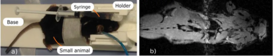
The goal of the in-vivo trials with the proposed coil was to demonstrate that the latter was capable of dual-nuclei imaging without replacing and retuning the setup. In the corresponding setup, a small syringe con-taining a fluorine compound was attached to a mouse under anesthesia, as shown in Fig. 8(a). In Fig. 9, images for the fourteen adjacent transverse slices are displayed in a gray color scale showing the anatomy of the mouse body as well as the water inside the syringe. The corresponding images acquired at 19F are overlaid with the 1H images
and mapped with a jet color scale. As expected, only the syringe filled with the fluorine compound gave any signal. An example of a coronal 1H image of the whole mouse body is presented in Fig. 8(b). No fluorine is present in
this plane covering only the mouse body.
Discussion
An array of the given number N of half-wavelength wires supports N eigenmodes with different resonant frequen-cies. These resonances result from hybridization of the electric-dipole mode resonance of a single half-wavelength wire. This hybridization effect is due to the interaction between identical coupled resonant elements of an array. The hybridization effect in a periodic wire structure may lead to novel designs of RF-coils for MRI. Thus, the excitation of hybridized eigenmodes in arrays of coaxial resonators has been used in TEM-coils15. By exciting
such modes in resonant metasurfaces it is possible to locally improve SNR of an external RF-coil in 1.5 T MRI. It has recently been shown16 that low-profile wire metamaterial-inspired resonators filled with water can serve as
artificial resonant substrate locally increasing SNR of body coils. It has also been proposed that the hybridized eigenmodes excited in a system of four λ/2-wires could be used in a novel volumetric preclinical RF-coil for 7 T17.
Among the hybridized eigenmodes of the long-wire and the short-wire resonators, there is one with all the strip electric currents flowing in-phase. This mode has a similar RF-field as the dipole mode of a single resonant wire and a huge radiation leakage loss. In fact, this radiation efficiency is useful for body imaging at 7 T to extend the B+
1 penetration and improve transmit capabilities. It is necessary for all other eigenmodes to have some
out-of-phase currents pairs. A pair of currents with opposite phases produces a magnetic field localization nearby, which can provide an appropriate filling factor of a sample with dimensions comparable to the distance between the currents of the pair. In other words, for higher-order modes the H-field decays faster as function of the dis-tance from the resonator in the normal direction. This is the common property of both of the resonators of peri-odic strips under consideration: the long-wire and the short-wire resonators.
For the long-wire resonator (left column in Fig. 2), all the modes have a cosine-like field distribution of the nor-mal magnetic field component in the longitudinal direction (along the strips). At the same time, the distribution has a standing-wave shape with between one and five lobes in the transverse direction with respect to the strips. The number of lobes is related to the order of the mode. Note that in Fig. 2, the eigenmodes are sorted according to the number of standing-wave lobes (the order of the standing-wave resonance). The positive (0) or negative (π) phases of strip currents producing the mode patterns are indicated in each pattern by ‘+’ or ‘−’ symbols to the right of the field color plots. It can be seen that the most homogeneous field pattern (Mode 1, Fig. 2(c)) corresponds to the highest resonant frequency. In contrast, Mode 5 having five standing-wave lobes, resonates at the lowest frequency. All the simulated resonant frequencies for modes 1–5 are compared for the two resonators in Table 1.
Figure 8. In-vivo setup including mouse under anesthesia and syringe containing fluorine compound (a) and
anatomic gradient echo coronal-plane image of mouse acquired using the manufactured dual-nuclei coil (b).
Figure 9. In-vivo anatomic gradient echo axial-plane images of mouse and 19F images of syringe with a mixture
of 60% 2-2-trifluoroethanol and 40% water attached to mouse body in fourteen different slices acquired using proposed dual-nuclei coil.
tion of the capacitive coupling between adjacent strips for the short-wire resonator than for the long-wire one. In the two resonators under discussion, the mode with the most homogeneous pattern of the normal H-field component is Mode 1 (Fig. 2(c,d)). From Figs. 3 and 4, one can see that this mode has the slowest field decay as the observation point goes away from the plane of strips. It has the lowest resonance frequency of 264.4 MHz for the short-wire resonator, while it has the highest resonance frequency of 322.4 MHz for the long-wire resonator. It can be observed that the field decays faster for higher numbers of lobes. For RF-coil application, one can expect that the modes with better in-plane homogeneity of the normal H-field component show better penetration into a subject and higher B+
1 per power efficiency at a depth. It should be noted that odd and even modes must be
compared separately, as even modes have zero H-field at the center of the resonator. The highest penetration depth can be expected from Mode 1 (Fig. 2(c,d)). The distribution of electric current phases of this mode provides the field in the vicinity of the resonator is similar to the field of a long surface loop coil. If one aims to localize the field pattern in a subject’s surface layer, the mode with the most inhomogeneous normal magnetic field and cur-rent phases should be excited in the resonator (namely Mode 5, Fig. 2(k,l)). This mode is equivalent to a set of five narrow and long loop surface coils, where each loop is one period in width and the neighboring loops are excited out-of-phase, resulting in low field penetration.
In both long-wire and short-wire resonators, it is possible to excite a variety of eigenmodes, which differ by their resonant frequencies and field penetration depths. If the two resonators are combined in the same RF-coil, one can manage its field penetration into a subject at two different Larmor frequencies by selecting appropriate resonant eigenmodes (one selected mode from each of the two resonators). The two different implementations, i.e. the long and the short resonator, were used to demonstrate that the multi-wire resonator can be properly designed for a given length. If there is no capacitive loading, it is possible to use a half-wave length, but if one aims to make the wires shorter, a capacitive loading must be used according to the given theory. Significantly, the multimode principle holds in both cases. Two completely different lengths and the perpendicular positions of the combined resonators give minimal parasitic inductive coupling, which makes the coil easier in terms of individ-ual tuning and matching at two Larmor frequencies.
For a dual-nuclei MRI, one needs to operate at two different Larmor frequencies, possibly with the same or different field patterns depending on the application. In the aforementioned resonators, it could be possible to use two of N eigenmodes exciting them at two different Larmor frequencies. However, for neither the long-wire nor the short-wire resonator, the resonant frequencies of two different eigenmodes cannot be tuned independently. Therefore, in the proposed coil, we have combined the two resonators into the same design by using just one eigenmode from each of them. Therefore, in the proposed design, the short-wire resonator is responsible for 19F,
while the long-wire resonator is responsible for 1H. The small overlap area of the two resonators in comparison
to the area of the long-wire resonator minimizes their mutual coupling. On the other hand, since the strips of the short-wire resonator are arranged perpendicularly to the B0 direction and the typical bore diameter of a 7 T
pre-clinical bore is only 90 mm, the resonator must be considerably shortened in comparison to the half-wavelength. This can be achieved by capacitive connection in each pair of strips18 as shown in Fig. 1(c). This self-resonant
geometry, comprising periodic metal wires and capacitive patches at their ends, was inspired by mushroom high-impedance surfaces19 and realized by connecting each printed shortened strip of the resonator end to a
rec-tangular copper patch of the side lengths b = 9 and c = 9.5 mm. All the patches from both ends of the strips were printed on two separate Rogers 4003 C grounded substrates of the thickness t = 0.508 mm (see Figs 1(c) and 2(b)). The idea of miniaturization by connecting adjacent strips through capacitive loads can be understood from the following example of the resonator with only two strips. The long-wire resonator with two strips of the width w and the separation a, acts as a TEM-transmission-line segment with two open ends. Even if the strips are printed on a thin dielectric substrate, the initial resonant length of this resonator is approximately equal to L1 = λ/2, where
λ is the wavelength in free space (see Fig. 1(b)). In contrast, in the short-wire resonator, the parallel strips are con-nected at both ends to each other through two structural capacities, each one realized as a rectangular patch over a grounded substrate. The resonator, together with its equivalent circuit, are shown in Fig. 1(c). From the circuit, it is possible to derive the formula for the resonant length L2 shortened due to the capacitive loads:
λ π π = − + −∞ < < − L WX X W X W 2 arctan 2 , ; (1) 2 2 2 λ π = − − < < L WX X W W X 2 arctan 2 , 0; (2) 2 2 2
The structural load reactance X can be calculated from a series connection of two similar capacities Cpatch
ω
= −
X
C2 ,patch (3)
where ω = 2πf is the angular frequency and Cpatch is given by
ε ε = ⋅ . C b c t (4) r patch 0
The formulas (1-2) can be used for the estimation of the miniaturization factor due to capacitive loading. In other words, one can calculate the ratio L1/L2 for the given geometric parameters of patches and strips. For the
above considered geometric parameters a, b, c and w at 300 MHz using the analytical formula for the wave imped-ance W of an edge-coupled strip line20, one can obtain L
1/L2 = 4.3. However, in the real resonator configuration
with six strips, the above formulas give only an approximation of the lengths of shortened strips. The precise values of L1 and L2 for tuning at the given Larmor frequencies depend on the orders of selected eigenmodes and
can be accurately worked out numerically. The specific numerically determined length of strips of the short-wire resonator was L2 = 72 mm, while the length of the long-wire resonator was L1 = 434 mm.
The whole proposed coil (see Fig. 1(a)) has been numerically calculated in the realistic MRI setup (with a phantom and the RF-shield) to demonstrate its dual-frequency operation. For the two Larmor frequencies, cor-responding to the nuclei of interest 19F and 1H, we decided to select the following modes: Mode 1 of the short-wire
resonator and Mode 3 of the long-wire resonator respectively. This choice was made to demonstrate the flexibility of the proposed design in terms of the field penetration depth for a given coverage of the sample’s surface. Thus, at 282.6 MHz, we expected to reach a high penetration depth due to the first mode, while having a strong surface localization at 300.1 MHz due to the third mode. Provided that the aforementioned modes belong to different resonators, it is easy to tune their resonances to the Larmor frequencies almost independently by varying the lengths of the corresponding strips. Matching at both frequencies was achieved by adjusting their positions with respect to a common small loop feed connected to a 50-Ohm port. The resulting simulated frequency curve of the reflection coefficient S11 (dotted red line in Fig. 5(a)), shows that indeed dual-frequency tuning and matching is
possible with the specific geometric parameters of the proposed coil (| |S11 is much lower than −10 dB at both
Larmor frequencies) with no lumped capacitors required. The magnetic field distributions created by the coil at these frequencies are presented in Fig. 6(a,c) and Fig. 6(b,d). As can be seen from the comparison of Fig. 6(b) and Fig. 6(d) with Fig. 2(d) and (g), the RF-field distributions obtained with the assembled coil are mostly determined by the desirable eigenmodes of the short-wire and long-wire resonators. However, a small field distortion at both frequencies can be observed in the location where the two resonators overlap (i.e. the location of the smaller short-wire resonator). The reason for this distortion is an inductive coupling between the selected eigenmodes of the resonators. The resonant frequency of each resonator (especially the frequency of the first-order mode) also becomes sensitive to tuning of the other resonator. Fortunately for the considered position of the two resonators, this sensitivity to the neighboring resonator is much weaker than the sensitivity to the individual tuning param-eter of the coil, i.e. the length of the wires. Comparing the distributions inside the phantom at the two Larmor frequencies (Fig. 6(a,c)), it can be concluded that the field penetration at 282.6, due to Mode 1 of the short-wire resonator, is indeed deeper than that of the long-wire resonator’s Mode 3 at 300.1 MHz. This result is in qualitative agreement with the curves of Fig. 4. It should be noted that from the field maps in Fig. 6(a,c), one can clearly determine which resonator is responsible for excitation of the phantom at the Larmor frequencies. Therefore, as shown in the simulation, the proposed coil design allows tuning and impedance matching at two predefined Larmor frequencies using no lumped capacitive elements due to resonant excitation of the selected eigenmodes.
Despite the orthogonal orientation of the two resonators and the relatively small size of the short-wire reso-nator, the effect of their mutual coupling is still observable. Due to this effect and the influence of the RF-shield, the resonance frequencies of the selected modes moved from 309.9 MHz (Mode 3 of the long-wire resonator) and 264.4 MHz (Mode 1 of the short-wire resonator) to 300.1 and 282.6 MHz respectively. It should be noted that since the mutual coupling of the resonators is relatively weak, their resonant frequencies are mostly dependent on the length of their own strips.
By additional numerical simulation, we studied the combination where the first mode is excited in both the short-wire and the long-wire resonator. Simulation results show that inductive coupling between resonators is higher when the first mode is excited in both of them. This can be observed in Fig. 6, where the normal magnetic field component (e, j) and B+
1 magnitude for 1 W of accepted power (f, h) of the modified coil is shown at 282.6
and 300.1 MHz. Despite both patterns being distorted due to the mutual coupling, the B+
1 magnitude in the
phan-tom at 300.1 MHz is higher when using the first mode of the long-wire than when using the third mode. Moreover, the distribution with the first mode is more uniform than with the third one. Significantly, since in the short-wire resonator in both compared cases we excited the same first mode, the B+
1 magnitude and distribution at
282.6 MHz was hardly affected. This clearly demonstrates that with the proposed design one can select desirable operational eigenmodes in the two resonators of the coil.
The design, with Mode 1 of the short-wire and Mode 3 of the long-wire resonator, has been manufactured and tested on the bench and in MRI scans. The two S11 curves measured with a VNA on the bench (dashed blue curve
in Fig. 5(a)) and using the MR system (solid green curve in Fig. 5(a)) demonstrate good agreement with the sim-ulated data. The difference in S11 levels at the two resonances and the presence of additional parasitic resonances
can be explained by the influence of a realistic MR-system’s bore geometry and the gradient system configuration, which was not considered in simulations. However, the experimental results confirm sufficient matching ( < −S11 10 dB at both the Larmor frequencies) required for dual-nuclei scanning.
The same coil setup with the phantom was used in the MRI scans. Comparing the obtained phantom images, one can conclude that the SNR decays with the depth in the phantom for 1H much faster than for 19F, which agrees
with the numerically calculated field plots in Fig. 6(b,d). The SNR of the hydrogen image is also lower since the distance to the long-wire resonator from the phantom is slightly larger than the distance to the short-wire resona-tor. In fact, one could replace the long-wire and the short-wire resonators by each other to improve SNR in the top surface layer of the phantom for 1H. On the top left of the 19F image, a dark area can be observed. The origin of this
effect is a high intensity of the B+
1 in close proximity to the short-wire resonator, which is disposed just above the
phantom. The flip angle in this part of the phantom becomes larger than the optimal one (close to 90 degrees) and is referred to as an overflip. The obtained phantom images clearly demonstrate that the field distributions created by the coil at two Larmor frequencies are almost similar in the axial direction of the MR-system, while the pene-tration depths are significantly different. This behavior of the coil results from the multi-mode nature of the periodic wire resonators and is determined by the selected eigenmode properties, as expected from simulations.
The obtained in-vivo images, presented in Figs 8 and 9, demonstrate that the designed coil is capable of 1H
anatomic imaging of the top part of a body of a small animal with a wide coverage area in the coronal plane. The purpose of the obtained images is to demonstrate the capability of the coil to consequently give a signal at the two Larmor frequencies with a living subject without any adjustments. A quantitative comparison of the coil imaging capabilities to existing coils including in-vivo imaging is the subject of future work. As was previously shown, the limited B+
1 penetration depth of the proposed coil at the Larmor frequency of 1H is due to the properties of the
selected Mode 3 of the long-wire resonator. At the same time, the field of view of the coil is long in the B0 direction
covering all the body length of a small animal, which also agrees with theoretical predictions. The coil was also capable of 19F imaging of the syringe under test using the same setup without retuning the coil. The performed
dual-nuclei imaging has an appropriate quality for various biomedical applications of 19F/1H MRI.
Methods
Eigenmodes of wire metamaterial-inspired resonators.
In order to numerically calculate the reso-nant frequencies of the two wire metamaterial-inspired resonators of the proposed coil (see Fig. 1(a)) and their eigenmode field distributions, we have made simulations using the Eigenmode Solver in CST Microwave Studio 2016 commercial software. For the short-wire and the long-wire resonators, the geometric parameters are illus-trated in Fig. 2(a,b). Both resonators are single-layer flat periodic arrays of N = 6 thin printed copper strips of the width w = 1 mm and periodicity a = 10 mm. The substrate of the printed circuit board was 0.508-mm-thick Rogers 4003 laminate with permittivity εr = 3.38, and the dielectric loss tangent 0.0027. The long-wire resonatordepicted in Fig. 2(a) has the length of strips L1 = 434.8 mm, which is comparable to one half of the wavelength
at 300 MHz. The long-wire resonator was modeled alone in the lossless approximation, without a subject and a feeding loop. For the short-wire resonator, the same numerical eigenmode analysis was performed separately. The following geometric parameters of the short-wire resonator were set: L2 = 72 mm, b = 9 mm and c = 9.5 mm.
All the patches from both ends of the strips of the short-wire resonator were printed on two separate Rogers 4003 grounded substrates of the thickness t = 0.508 mm (see Figs 1(a) and 2(b)). In the simulation, the number of ana-lyzed modes was set to five for both resonators. The calculation domain was bounded by distant PEC walls from all sides. No phantom was included in the eigenmode simulation.
Design and simulation of RF-coil.
The whole proposed coil, assembled of two metamaterial-inspired resonators and a small loop feed, was simulated using Frequency Domain Solver in CST Microwave Studio 2016 together with a homogeneous phantom and a perfectly conducting cylindrical RF-shield of the diame-ter of 90 mm. The long-wire resonator was located on top of the short one as depicted in Fig. 1(a), so that the separation between their PCBs was 9 mm. A small inductively coupled feed was placed between the resonators and implemented as a flat annular copper ring of the width 4 mm and the external radius 20 mm, printed on 0.508-mm-thick Rogers 4003 C substrate. The loop was fixed 2 mm away from the plane of the long strips and 7 mm away from the plane of the short strips. As a result, a three-layer stack of PCBs was composed which oper-ated as a dual-frequency surface coil. The length of the long-wire resonator and the mutual position of the latter and the feeding loop differs from the respective dimensions for mode 1–1 combination of the coil. Dimensions of the coil both for 1–3 and 1–1 combinations are listed in Table 2.The coil produced an RF-field inside the tightly located cylindrical phantom with the diameter 40 mm, length 75 mm and material properties εr,phantom = 39 and tanδ = 0.06. In the simulation, the loop was driven by a lumped
50-Ohm port connected to its split, and the small loop itself excited one selected eigenmode in each of the two wire resonators. The parameters of the resonators were the same as previously used for eigenmode analysis. The values L1 and L2 were chosen in a parametric sweep performing multiple field simulation. The optimization goal
was to achieve the calculated | |S11 well below −10 dB at both considered Larmor frequencies. Impedance match-ing was reached by variation of the distances between the three aforementioned parallel PCBs of the RF-coil.
Once tuning and matching was reached at the two desired Larmor frequencies, the circularly polarized RF field
+
B1 rotating in the axial plane with respect to the static field of the magnet corresponding to the accepted power of 0.5 W, was calculated using the template-based post-processing routine in the CST Microwave Studio. Sensitivity to loading variations of the proposed coil was studied through a number of simulations where the dimensions of the phantom were changed: radius of the phantom from the original value R = 20 mm to 0.8*R and 1.2*R and length of the phantom from L = 75 mm to 0.8*L and 1.2*L.
On-bench measurements.
For on-bench and MRI experiments, the proposed coil was manufactured by manually assembling separate PCB parts, shown in the inset of Fig. 10(a), based on a common specially designed 3D-printed bed. The bed included a holder supporting the antenna parts shown in Fig. 10(a). The PCB parts in Fig. 10(a) are labeled as: 1–loop feed with SMA connector, 2–short-wire resonator with soldered PCBs supporting capacitive patches, 3–long-wire resonator. The bed also includes the base supporting the coil and a removable holder for a scanned sample, i.e. a small animal (see Fig. 10(b)). The whole bed fits the dimensions of a 90-mm diameter bore of a preclinical MRI. In Fig. 10(a), one can also observe the feeding coax with the RF-cable trap. The parts of the bed were manufactured by 3D printing.All the geometry parameters of the two resonators in the manufactured coil correspond to ones chosen in the previously discussed simulation. The short-wire resonator was constructed of three 0.508-mm-thick Rogers 4003 PCBs: one supporting shortened copper strips and two grounded side PCBs with rectangular patches. All six strips from both ends were manually soldered to the corresponding patches printed on two-sided PCBs. The long-wire resonator was represented only by a single Rogers 4003 PCB with strips without connection to any capacitive loads. The coil was fed with a coaxial 2-mm 50-Ohm cable connected to the printed non-resonant circular loop through the cable trap with a cable ring shunted by a variable capacitor. The homogeneous phantom was represented by a cylindrical plastic can with the diameter 40 mm and height 75 mm filled with the solute of 60% 2-2-trifluorethanol and 40% water. The permittivity of 39 and the dielectric loss tangent 0.06 were measured for this liquid in the frequency range 100–400 MHz using the calibrated coaxial line section EpsiMu connected to the vector network analyzer (VNA) Anritsu MS2036C, and the obtained values were used in the performed numerical simulations.
In order to ensure proper tuning and impedance matching the reflection coefficient | |S11 of the coil was
meas-ured first with the vector network analyzer (VNA) Anritsu MS2036C connected through a long calibrated cable to the coil located inside the bore of Bruker PharmaScan 7 T MR system. The result is shown in Fig. 5(a) with a dashed blue curve.
MRI experiments with phantom and in-vivo.
In order to validate the obtained tuning and impedance matching of the experimental coil, | |S11 was again measured by means of the MR-system within its two operationalbands (represented in Fig. 5(a) with the solid green curves).
The coil was tested by imaging of the phantom by scanning in the MR-system using the pulse sequence gradi-ent echo (FLASH) TR/TE = 2000/2.4 ms with an isotropic voxel 0.7 × 0.7 × 0.7 mm3, the FOV was 44.8 × 44.8 mm,
the number of averages was 1 and the flip angle was 90°. This flip angle was adjusted by Bruker reference power adjustment at the beginning of the scan in a horizontal slice located on the surface of the imaged sample.
In-vivo mouse acquisition was performed in accordance with European Union and French laws on animal
experimentation (project authorization number: 12–058, site authorization number: B-91-272-01). The project authorization was delivered by the Ministry of Higher Education, Research and Innovation in France based on recommendations by the local ethical committee CETEA–CEA DSV IdF number 44. A mouse was placed under anesthesia (isoflurane 1-2%) in front of the center of the feeding loop. A 1 ml syringe filled with a mixture of 60% 2-2-trifluoroethanol and 40% water was attached to the back of the mouse as shown in Fig. 8(a). By scanning
Figure 10. Experimental RF-coil: (a) PCB parts including loop feed, short-wire resonator and long-wire
resonator and their assembly with spacer, phantom and RF-cable; (b) bed parts: holder for resonators and for small animal.
thickness of 0.5 mm, the FOV was 80 × 32 mm, the number of averages was 1 and the flip angle was 90° (see the obtained whole-body image in Fig. 8(b)).
Conclusion
In this work, a new design for a dual-nuclei preclinical RF-coil was proposed and characterized. The opera-tional principle of the coil is based on resonant excitation of eigenmodes in a pair of multi-mode wire metamaterial-inspired resonators. It was numerically and experimentally shown that by proper selection of the excited eigenmodes, one can control the penetration depth into a subject, i.e. to efficiently excite the whole body or just a particular surface of a small animal. The resonant frequencies of the selected modes can be tuned by geometrical properties of the resonators of the coil, while impedance matching is determined by mutual posi-tions of the resonators and the feeding annular loop. Proof-of-concept MRI tests on a phantom and in-vivo were performed showing imaging capability of the proposed coil at two Larmor frequencies of 1H and 19F at 7 Tesla.
The proposed coil design is also compatible with multi-nuclei MRI applications using other nuclei (e.g. 23Na31,P
etc.) since both the short and the long-wire resonators can be tuned to various Larmor frequencies by adjusting their length and the parameters of patches (providing the distributed load capacity for the short-wire resonator). Crucially, the proposed self-resonant design is cheap as it contains no variable non-magnetic capacitors for tuning and matching and can be constructed of just a few PCB parts which are movable against each other.
References
1. Doty, F. D., Entzminger, G., Kulkarni, J., Pamarthy, K. & Staab, J. P. Radio frequency coil technology for small-animal MRI. NMR in
Biomedicine 20, 304–325 (2007).
2. Hoult, D. The NMR receiver: a description and analysis of design. Progress in Nuclear Magnetic Resonance Spectroscopy 12, 41–77 (1978).
3. Ginsberg, D. & Melchner, M. J. Optimum geometry of saddle shaped coils for generating a uniform magnetic field. Review of
Scientific Instruments 41, 122–123 (1970).
4. Tropp, J. The theory of the bird-cage resonator. Journal of Magnetic Resonance (1969) 82, 51–62 (1989).
5. Hayes, C. E., Edelstein, W. A., Schenck, J. F., Mueller, O. M. & Eash, M. An efficient, highly homogeneous radiofrequency coil for whole-body NMR imaging at 1.5 T. Journal of Magnetic Resonance (1969) 63, 622–628 (1985).
6. Doty, F. D., Entzminger, G. & Hauck, C. D. Error-tolerant RF litz coils for NMR/MRI. Journal of Magnetic Resonance 140, 17–31 (1999).
7. Naritomi, H., Kanashiro, M., Sasaki, M., Kuribayashi, Y. & Sawada, T. In vivo measurements of intra- and extracellular Na+ and water in the brain and muscle by nuclear magnetic resonance spectroscopy with shift reagent. Biophysical Journal 52, 611–616 (1987). 8. Atalar, E. et al. High resolution intravascular MRI and MRS by using a catheter receiver coil. Magnetic Resonance in Medicine 36,
596–605 (1996).
9. Muftuler, L., Gulsen, G., Sezen, K. & Nalcioglu, O. Automatic tuned MRI RF coil for multinuclear imaging of small animals at 3 T.
Journal of Magnetic Resonance 155, 39–44 (2002).
10. Wosik, J. et al. Superconducting array for high-field magnetic resonance imaging. Applied Physics Letters 91, 183503 (2007). 11. Hu, L. et al. A generalized strategy for designing 19 F/1 H dual-frequency MRI coil for small animal imaging at 4.7 Tesla. Journal of
Magnetic Resonance Imaging 34, 245–252 (2011).
12. Alecci, M. et al. Practical design of a 4 Tesla double-tuned RF surface coil for interleaved 1 H and 23Na MRI of rat brain. Journal of
Magnetic Resonance 181, 203–211 (2006).
13. Meyer, K. L. & Ballon, D. A 3 × 3 mesh two-dimensional ladder network resonator for MRI of the human head. Journal of Magnetic
Resonance, Series B 107, 19–24 (1995).
14. Voss, H. U. & Ballon, D. J. High-pass two-dimensional ladder network resonators for magnetic resonance imaging. IEEE
Transactions on Biomedical Engineering 53, 2590–2593 (2006).
15. Peshkovsky, A. S., Kennan, R. P., Fabry, M. E. & Avdievich, N. I. Open half-volume quadrature transverse electromagnetic coil for high-field magnetic resonance imaging. Magnetic Resonance in Medicine 53, 937–943 (2005).
16. Slobozhanyuk, A. P. et al. Enhancement of magnetic resonance imaging with metasurfaces. Advanced Materials 28, 1832–1838 (2016).
17. Jouvaud, C., Abdeddaim, R., Larrat, B. & de Rosny, J. Volume coil based on hybridized resonators for magnetic resonance imaging.
Applied Physics Letters 108, 023503 (2016).
18. Glybovski, S. B. et al. Capacitively-loaded metasurfaces and their application in magnetic resonance imaging. In 2015 Radio and
Antenna Days of the Indian Ocean (RADIO), 1–2 (2015).
19. Sievenpiper, D., Zhang, L., Broas, R. F. J., Alexopolous, N. G. & Yablonovitch, E. High-impedance electromagnetic surfaces with a forbidden frequency band. IEEE Transactions on Microwave Theory and Techniques 47, 2059–2074 (1999).
20. Cohn, S. B. Shielded coupled-strip transmission line. IRE Transactions on Microwave Theory and Techniques 3, 29–38 (1955).
Acknowledgements
This work was supported by the Ministry of Education and Science of the Russian Federation (project No. 14.587.21.0041 with the unique identifier RFMEFI58717X0041). This project has received funding from the European Union’s Horizon 2020 research and innovation programme under grant agreement No 736937. The authors would like to thank Prof. Constantin Simovski for useful discussions.
Author Contributions
Theoretical analysis was carried out by A.H., A.N., S.G., R.A. Experiments were conducted by A.H., S.G., R.A., B.L., E.G., D.B., L.N., P.S. Manuscript was written by A.H., A.N., S.G., B.L., I.M., R.A. and pictures were made by A.H., A.N., S.G., B.L. All the authors analyzed and discussed the results. All the authors reviewed the manuscript.
Additional Information
Competing Interests: The authors declare no competing interests.
Publisher's note: Springer Nature remains neutral with regard to jurisdictional claims in published maps and
institutional affiliations.
Open Access This article is licensed under a Creative Commons Attribution 4.0 International
License, which permits use, sharing, adaptation, distribution and reproduction in any medium or format, as long as you give appropriate credit to the original author(s) and the source, provide a link to the Cre-ative Commons license, and indicate if changes were made. The images or other third party material in this article are included in the article’s Creative Commons license, unless indicated otherwise in a credit line to the material. If material is not included in the article’s Creative Commons license and your intended use is not per-mitted by statutory regulation or exceeds the perper-mitted use, you will need to obtain permission directly from the copyright holder. To view a copy of this license, visit http://creativecommons.org/licenses/by/4.0/.