Drawing on the World: Sketch in Context
by
Andrew Correa
Submitted to the Department of Electrical Engineering and
Computer Science
in partial fulfillment of the requirements for the degree of
Master of Science
at the
MASSACHUSETTS INSTITUTE OF TECHNOLOGY
September 2009
©
Massachusetts Institute of Technology 2009. All rights reserved.
Author.
...
Department of Electrical Engineering and Computer Science
September 04, 2009
Certified by ....
-
...
Randy Davis
Professor of Computer Science and Electrical Engineering
Thesis Supervisor
Accepted by ...
Terry P. Orlando
Chair, Department Committee on Graduate Students
MASSACHUSETTS INSTWE OF TECHNOLOGY
SEP 3 0
2009
ARCHIVES
LIBRARIES
---Drawing on the World: Sketch in Context
by
Andrew Correa
Submitted to the Department of Electrical Engineering and Computer Science on September 04, 2009, in partial fulfillment of the
requirements for the degree of Master of Science
Abstract
This thesis introduces the idea that combining sketch recognition with contextual data-information about what is being drawn on-can improve the recognition of meaning in sketch and enrich the user interaction experience.
I created a language called StepStool that facilitates the description of the re-lationship between digital ink and contextual data, and wrote the corresponding interpreter that enables my system to distinguish between gestural commands is-sued to an autonomous forklift. A user study was done to compare the correctness of a sketch interface with and without context on the canvas.
This thesis coins the phrase "Drawing on the World" to mean contextual sketch reconition, describes the implementation and methodology behind "Drawing on the World", describes the forklift's interface, and discusses other possible uses for a contextual gesture recognizer. Sample code is provided that describes the specifics of the StepStool engine's implementation and the implementation of the forklift's interface.
Thesis Supervisor: Randy Davis
Acknowledgments
I would like to thank Professor Randy Davis for his insight and feedback. I thank Seth Teller for his support. I thank the members of the Multimodal Understanding group and the Agile Robotics group for their feedback and support. I thank my parents and Ashley Murray for their encouragement, without which I would not have had the strength to carry this work through to completion.
Also, I thank Ashley Murray, Prof. Randy Davis, and Matthew Walter, for proofreading my thesis and I thank Ali Mohammad for his help. They deserve all the credit for any errors.
Contents
1 Introduction 13
1.1 Sketch Ontology ... ... .. .. 14
1.2 Task Dom ain ... ... 15
1.2.1 Pallets . . . . . . . ... . .. . 16
1.2.2 Supply Support Activities ... 17
1.3 Forklift World Model ... . .. . .... ... 18
2 Drawing on the World: A Contextual Gesture Recognizer 21 2.1 Vocabulary of Gestures ... . 21 2.2 Resolving Ambiguity ... ... 24 2.2.1 Circle Ambiguity ... 25 2.2.2 Dot Ambiguity ... 25 2.2.3 X Ambiguity ... 26 2.3 Grounding Gestures ... 27
2.4 Example Use Case ... 27
3 StepStool 33 3.1 Structure . . . . . . . .. . . .. 34
3.1.1 Scenic Item Description Grammar . ... 35
3.1.2 Shape Description Grammar ... 35
3.1.3 Gesture Description Grammar ... 36
3.2 Syntax and Semantics ... 38
3.2.1 Description Boundaries ... 38
3.2.2 Shape and Scenic Item Attributes . . . . 3.2.3 Gesture Conditions ...
3.2.4 Constants ...
3.2.5 Other Gesture Statements ... 3.2.6 Gesture Modifiers. . ... 3.3 Forklift StepStool File Example . ...
3.3.1 Scenic Item Descriptions . . . ... . 3.3.2 Shape Descriptions . . . ...
3.3.3 Gesture Descriptions ... . .
4 System Architecture
4.1 StepStool Engine Implementation ... 4.1.1 The File Input Module . ... 4.1.2 The Scene Builder. . ...
4.1.3 The Evaluation Module . . . . 4.2 StepStool Engine API . ...
4.2.1 File Input ... 4.2.2 Scene Building ... 4.2.3 Classification Invocation ... 4.3 An Example Application . ...
4.3.1 Control Flow ...
4.3.2 Loading the StepStool Description File 4.3.3 Handling the World Model ... 4.3.4 Handling Stroke Recognition ...
5 User Study 5.1 Setup . . . . 5.1.1 Scenarios ... 5.1.2 Participants ... 5.1.3 Procedure ... 5.2 Accuracy Measurements ... ... 38 ... 38 ... 39 ... 39 ... 40 ... 41 ... 42 . . . 44 . . . 47 65 S. . . . . .. 65 . . . . .. 65 . . . .. . .. . 67 . . . .. . . . . 67 . . . .. . . . . 67 I _ I.-li.
5.2.1 Functional Accuracy ... 68 5.2.2 Theoretical Accuracy ... 69 5.3 Results . . . .. . . . .. 69 5.4 A nalysis . . . .. . . . . . ... . 71 6 Future Directions 73 6.1 StepStool Improvements ... 73
6.1.1 M ore Base Shapes ... 73
6.1.2 Additional Functionality ... 74
6.1.3 Lifting Implementation Limitations . ... 75
6.2 Other Robotic Domains ... 76
6.3 Improved Usability of StepStool Engine . ... 76
6.3.1 OpenGL-like Interface ... 76
6.3.2 SQL-like Interface ... 76
7 Conclusion 79
A The StepStool File Used in the Forklift Project 81
B The Forklift Project's C Interface to the StepStool File 91 C Definition of Terms 107
List of Figures
1-1
1-2
1-3
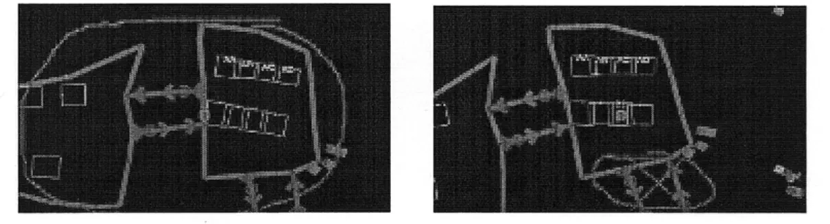
Strokes displayed in and out of context. . ... An N810 and a sample generated image. ...
The approximate coverage and positions of the cameras.
1-4 Two kinds of pallets. ...
1-5 A Supply Support Activity . ...
2-1 A pallet manipulation gesture for the ground..
2-2 Pallet placement commands. . ... 2-3 Interpretations of crossing out a pallet. ...
2-4 Movement gestures. ...
2-5 Area commands. ... 2-6 Spotter commands. ...
2-7 The Circle Ambiguity. ... 2-8 The Dot Ambiguity. ... 2-9 The X Ambiguity. ...
2-10 The starting state of the use case. ... 2-11 A truck arrives and a path is drawn. ... 2-12 2-13 2-14 2-15 2-16 2-17 .. 13 .. 16 .. 16 .. 17 .. 17 . . . . . 22 . . . . . 22 . . . . . 23 . . . 23 . . . 24 . . . 24 . . . 25 . . . 26 . . . 26 . . . . . 28 . . . . . 28
An unrecognized pallet being circled in the front camera view... An X is drawn to indicate a destination . . . . . A pallet bay is clicked, indicating the pallet is to be placed there.. A pair of pallets the system has recognized. . ... . A forklift is added . ... Both forklifts' work is complementary. ... . . . 29 29 29 .. 30 .. 30 .. 31
2-18 2-19 2-20 3-1 3-2 3-3 3-4 3-5 3-6 4-1 4-2 4-3 4-4 4-5 5-1 5-2 5-3 5-4 A valid path ...
An improved pallet bay scenic item description. An OpenGL API example ...
A SQL API example . ... . .. . . 75 . . .. . .. 75 . . . . 77 . . . . . 78 Pallet placement ... ... 31
A forklift failure mode ... 32
An "avoid region" gesture ... 32
The base class of all scenic descriptions. . ... . . 35
Backus Naur Form of a scenic description. . ... . . 36
The base class of all shape descriptions. . ... . . 36
Backus Naur Form of a shape description. . ... 36
Backus Naur Form of a gesture description. . ... 37
Pallet stacking StepStool description. . ... 41
A low-level overview of the StepStool engine's design. . ... 55
A high-level view of the foklift project's use of the StepStool engine. 60 Loading a StepStool description file into the engine in C. ... 62
Populating the StepStool engine's scene. . ... 62
Invoking StepStool classification and reacting to its output. ... 63
The four scenarios that users performed. . ... 66
Shape-to-command interpretation rules. . ... 68
Functional and theoretical accuracy. . ... 70
User study statistics. ... 70
6-1 6-2 6-3 6-4
Chapter 1
Introduction
Most current sketch recognition systems approach the task of recognizing a stroke by assuming nothing is being drawn on other than previous strokes. These systems treat the stroke as though it were drawn on a blank piece of paper or a white board, because it often is. They analyze only the timestamped point data of a human-drawn pen stroke, or a bit raster of the image the pen stroke created. This, by-and-large, seems to be because no applications that implement sketch recognition are built on top of systems that provide any other sort of canvas. As a result, there is no opportunity for knowledge other than which vocabulary of symbols is being drawn (e.g. circuit diagram symbols) to be incorporated into the recognition task.
If drawing occurred on something other than a blank screen, knowing what was being drawn on could be used to aid in sketch recognition. When someone draws
(a) Strokes out of context (b) Strokes in context
Figure 1-1: Strokes displayed in and out of context.
on an image of a football game in progress (as on television), the lines and marks made are understood differently than if those same lines and marks were drawn on a map. If those same lines and marks were drawn on a blank sheet of paper, they may not make any sense without further description (Figure 1-1). Just as the context within which strokes are made makes a difference in how those strokes are interpreted (e.g. "circuit diagrams"), what those strokes are drawn on also makes a difference.
1.1
Sketch Ontology
In any sketch-recognition system, appearance (what a sketch looks like) and mean-ing are related but clearly distmean-inguishable. The shape of a stroke determines how it is classified and hence what it means. There is a one-to-one mapping between appearance and meaning in a traditional system. As a result, traditional sketch recognition systems are shape recognizers.
The ontology of a contextual gesture recognition system differs from a tradi-tional system in that it separates appearance and meaning, and adds the concept of the scene-the world being drawn on. In this sort of system, there need not be a strict one-to-one mapping between shape and meaning. Instead, after a stroke is classified as a shape, it can be compared with what it is being drawn on-its scene-to determine its meaning and hence which action should be taken. As a result, where a traditional sketch recognition system classifies a stroke as a shape based on geometrical features and derives meaning, a contextual gesture recog-nition system continues the recogrecog-nition process by comparing the geometrically recognized shape with what the shape was drawn on, and classifies the shape as a gesture.
In a contextual sketch recognition system, we need to distinguish between the real world, the system's world model, and the scene being drawn on. The real world is the world you and I live in. The system's world model is an abstraction of the real world, consisting of information about the real world that the system finds
useful to perform its task. The scene is a different abstraction of the real world, consisting 2D representations of objects in the system's world model, or a video feed coming from a camera. When we make contextual comparisons, we compare the user's stroke with data about objects in the scene.
To facilitate the description of relationships between the scene and a user's strokes, I have developed a language called StepStool (Chapter 3). StepStool is a language meant not only to ease the burden on the programmer when describing these relationships, but also to be more transparent in its meaning than other lan-guages (e.g. C). To use the StepStool description language, I have created a StepStool engine that allows C programs to incorporate context in gesture recognition.
1.2 Task Domain
Members of the Agile Robotics project at MIT and Lincoln Labs developed an autonomous forklift capable of navigating and performing tasks in an army supply support activity, or SSA. The forklift is not intelligent enough to determine which task to perform, but it is intelligent enough to perform a task once a command has been given. These tasks entail navigating around an SSA and picking up and
dropping off pallets around it.
This forklift was designed to allow graceful recovery if it became stuck during the execution of a task. A human can take control and guide it through the difficult situation, should the need arise. These situations may occur if the forklift has judged that there is an obstacle too close to move safely, or it cannot recognize a pallet it has been instructed to pick up. Future versions of this project may include the ability to use hand signals to guide the forklift through such situations. Currently, however, a forklift operator must occupy the driver's seat of the forklift and operate it as though it were a normal forklift. Once the difficult situation has
been handled, autonomous operation may resume.
A ground supervisor issues commands to the forklift with a combination of speech and sketch, using a Nokia N810 internet tablet (Figure 1-2(a)). There are
(a) A Nokia N810 Internet (b) One frame of the generated top-down
Tablet video feed.
Figure 1-2: An N810 and a sample generated image.
(a) The approximate coverage of (b) The positions of the front and left cameras are the cameras. marked in red.
Figure 1-3: The approximate coverage and positions of the cameras.
four cameras mounted on the top of the forklift facing front, back, left, and right (Figure 1-3), that transmit video to the tablet. The supervisor draws on these images. Additionally, the forklift generates video from a top-down perspective (Figure 1-2(b)), which is also transmitted to the tablet and can also be drawn on.
1.2.1
Pallets
Pallets (Figure 1-4) are special rigging that allow forklifts to manipulate large packages. This rigging is often a simple wooden platform with holes, or slots on two or four sides. A forklift can insert its tines into the slots and lift the pallet to move it. This insertion is referred to as "pallet engagement." The locations can be special places on the ground, or places on a truck. A pallet's load can also be
Figure 1-4: These are two kinds of pallets: on the left is an empty JMIC (Joint Modular Intermodal Container), and on the right is a wooden pallet loaded with inert ammunition.
broken down into sub-parts. Thus, along the course of its transport, a pallet can slowly shed its contents, making it a versatile form of transport. For example, a pallet containing various tank parts can provide different parts to different units at
different points as the pallet is transported.
Some forklifts stack pallets on top of one another for more efficient use of space. This practice is called "pallet stacking." It is not supported by the forklift project.
1.2.2
Supply Support Activities
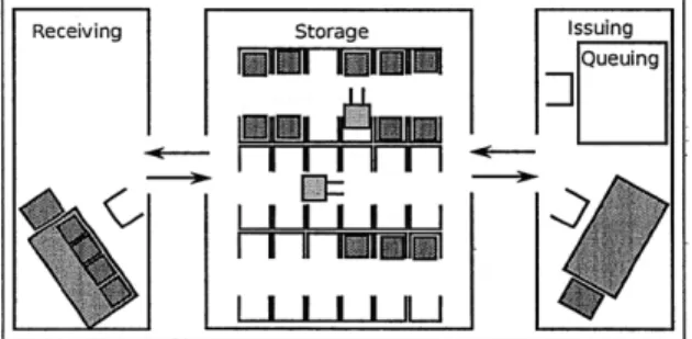
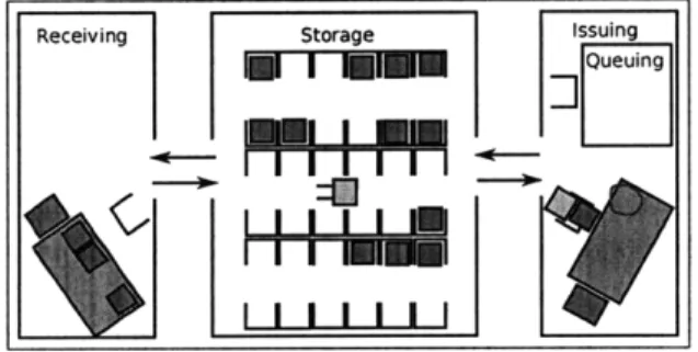
Figure 1-5: Trucks are unloaded in receiving (left) and loaded in issuing (right). The storage area (center) is where pallets wait between transfers off trucks in receiving and on trucks in issuing.
Figure 1-5 shows a possible layout of a supply support activity.1 A supply
support activity, or SSA, is one point in a series of depots along a supply train. It is made up of three areas: a receiving area, where trucks come full of pallets to unload, a storage area, which contains pallet bays where pallets are stored, and an issuing area, where empty trucks come and have pallets loaded onto them. There are lanes in between these three areas to reduce the risk of collisions, much like on a two-way road. The issuing area has a queuing area within it. As the name suggests, the queuing area is used to queue up pallets. If a truck will soon arrive in the issuing area, the pallets that are to be loaded on that truck can be placed in the queuing area in preparation for the truck's arrival. This expedites the process of loading the truck once it arrives.
The storage area stores pallets. It is made up of what are referred to as "pallet bays." Pallets in the storage area must be located in pallet bays. Pallets are either waiting for a truck to arrive in the issuing area so that they can continue to their final destination, or have reached their final destination and will be disassembled. Also, as noted above, a pallet can be partially disassembled in one SSA and continue with its remaining cargo to another SSA.
1.3 Forklift World Model
To enable the forklift to perform its tasks, it is given a concept of the supply support activity it operates in. The forklift's world model includes the SSA defined in terms of boundaries, pallet bays, truck stop locations, and summon locations. Boundaries follow the edges of each of the areas. The forklift is not supposed to cross these boundaries. If the forklift sees no way to complete its task as a result of this, it will declare itself stuck and a human will have to navigate it through the difficult maneuver.
As mentioned above, pallet bays are locations where the forklift can rest a pallet
1
Technically, this is not a full SSA, as there is no "turn-in" area. The turn-in area was not included because the scope of the project was limited for the first year of developments.
on the ground. These include all the pallet bays in the storage area, and another in the queuing area. Truck stop locations are places where trucks stop to be loaded or unloaded. There is a truck stop location in receiving and in issuing. There are
summon locations beside both of these truck stop locations. Summon locations are spots in the SSA that have been given a name. In Figure 1-5 there are 39 such locations. They are "receiving," "issuing," "queuing," and all the bays in the storage areas. The pallet bays in the storage area are given a pair of letters to label them. They are "storage A-A" through "storage A-F" along the top row, and "storage F-A" through "storage F-F" along the bottom row. The ground supervisor can issuing a verbal command such as, "Come to receiving" or "Come to storage E-C" and the forklift will go to the right place.
The forklift can classify different objects encountered in an SSA. It knows that a pallet is an object with slots that can be engaged and moved. It knows that people are objects that move and should be given wide berth. If a person approaches the forklift, it will pause its operation. Generally, a human will only need to approach the forklift when he plans on operating it manually. The forklift also knows about trucks, understanding that they can move, that they are larger than humans, that they carry pallets which can be engaged but that the truck itself cannot be engaged, and that the forklift should never interact with the pallets on the back of a moving truck. Finally, the forklift knows about obstacles. Obstacles include a number of things like boxes, walls, trucks, cones, and buildings. These are things that are understood to be immobile, and that the forklift knows it should not run over, hit, or engage.
Chapter 2
Drawing on the World: A Contextual
Gesture Recognizer
"Drawing on the World" is the compliment of drawing on a canvas (or whiteboard). It involves taking into account what is being drawn on when performing the sketch recognition task. The context provided by the world being drawn on can be used to disambiguate between valid gesture interpretations (Section 2.2), make sketch a more versatile and useful input mode (Section 2.3), and be generalized in a way that decreases the burden on the programmer (Chapter 3). This chapter discusses uses for drawing on the world by describing a Human-Robotic Interface (HRI), its
gesture vocabulary, and a use case example of full end-to-end operation.
2.1 Vocabulary of Gestures
The forklift can successfully navigate itself around an SSA and manipulate pallets. The commands given are low level, specific atomic tasks. We do not assume that the forklift is advanced enough to figure out how to unload a truck by itself but, if directed toward a pallet, we expect it to be able to pick-up that pallet. The forklift is aware of its surroundings to a limited extent. That is to say, it has the ability to distinguish between things in the SSA, including pallets, people, and trucks. The forklift will often perform this classification correctly, but we do not expect that it
will be correct 100% of the time. For these reasons, we chose the following set of gestures, which allow the ground supervisor to move the forklift, command it to manipulate pallets, and correct its perception of objects in the world.
(a) Circling a pallet on the ground. (b) The stroke after interpretation.
Figure 2-1: A pallet manipulation gesture for the ground. This is identical when the pallet is on the back of a truck.
Figure 2-1 shows some of the gestures that instruct the forklift what to do with pallets. Circling a pallet is a cue to pick it up, as is drawing a dot-or "clicking"-on the pallet. The difference is that when drawing a circle, the system is given a hint as to where the pallet is, so if the system has not detected that pallet yet, it will have help finding it.1
(a) Placing a pallet in a bay with the dot. (b) Placing a pallet on the ground with a circle.
Figure 2-2: Pallet placement commands.
Other pallet manipulation commands entail drawing X's on a pallet or circles or dots on the ground. When the forklift has something in its tines, circling a place on
'A dot cannot serve the same purpose, because the system's pallet detection module requires a conical region to be defined that includes the pallet and only the pallet. Including the vertical side of the truck or the pallet next to it within this conical region could confuse the pallet detection module and the circled pallet will not be found.
(b) Correcting forklift's view (not a pallet).
Figure 2-3: Interpretations of crossing out a pallet.
the ground or on the back of a truck is interpreted as an instruction to place a pallet on that spot (Figure 2-2). When the forklift is about to pick-up a pallet, crossing that pallet out tells the system not to pick it up (Figure 2-3(a)). When the system has mis-recognized an object-like a cardboard box-as a pallet, crossing it out tells the system that what it thinks is a pallet is not actually a pallet (Figure 2-3(b)).
(a) A path gesture. (b) A destination gesture.
Figure 2-4: Movement gestures.
Figure 2-4 shows movement commands that direct the forklift to a certain place or along a certain path. The supervisor can draw paths on the ground to indicate a general path to be followed (Figure 2-4(a)) and draw X's or dots on the ground to indicate end destinations (Figure 2-4(b)). The difference between drawing an X and a dot on the ground is that the system infers a desired end orientation from the direction of the second line of the X.
Circling a large part of the ground indicates that the forklift should not leave that area (Figure 2-5(a)). Circling a part of the ground and crossing it out indicates that the forklift is restricted from that area (Figure 2-5(b)). A person can be circled
-~t
(a) A command to stay in a region.
Figure 2-5: Area commands.
(a) A spotter being circled.
Figure 2-6: A spotter is watched for gesture.
(b) A spotter being crossed out.
cues between the circle gesture and the X
to indicate that he should be attended to as a spotter. In the future, we would like to implement a subsystem on the forklift that would recognize hand gestures and verbal utterances. Spotters are often used with human-operated forklifts when performing a precision maneuver. The circled person could then make hand gestures and speak to the forklift to guide it out of a tight spot, or through a difficult maneuver. To return the forklift to its normal mode of operation, the supervisor will cross out the spotter with an X. Currently, however, we require that an operator controls the forklift until the difficult maneuver is complete.
2.2 Resolving Ambiguity
This section shows examples of scenarios in which a gesture interface becomes more versatile by taking the scene into account.
~ _____
2.2.1
Circle Ambiguity
1
2
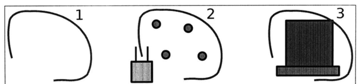
Figure 2-7: 1) A hand-drawn circle 2) The circle interpreted as a path 3) The circle interpreted as a "pick-up" or "find that pallet" gesture.
If an open circle is drawn (Figure 2-7-1) it could be a path, a "pick-up that pallet" command, or a "find a pallet" command. The stroke data alone cannot determine which of these three gestures it is. A stroke drawn on the top-down view, originating from the forklift and moving around obstacles (Figure 2-7-2) should be interpreted as a path. A stroke drawn in the front camera view and encompassing a pallet (Figure 2-7-3) should be interpreted as a pick-up gesture. As this example illustrates, large pen strokes drawn on the top-down view are more likely to be path gestures, even if they are circular, because they tend to be too large to include just one pallet. If neither of these sets of conditions are met there may be a pallet in the circle visible to the operator but not yet detected by the system. That gesture serves as a hint to the robot's perception module that there is a pallet to be found there. Once it is found, it can be picked up.
2.2.2
Dot Ambiguity
In Figure 8 we can see the same dot in three contexts: picking up a pallet (Figure 2-8-1), dropping off a pallet, (Figure 2-8-2), and going to a location (Figure 2-8-3). Consider the case in which the forklift's front-facing camera can see a pallet and the forklift recognizes it. Clicking on the pallet will cause the forklift to try to pick it up. Case 2 shows a situation where the click is interpreted as a drop off gesture, because the forklift knows that it has a pallet, is in front of a pallet bay, and that the dot is drawn on the bay. Case 3 shows the dot being interpreted as a summon
Figure 2-8: Dots that mean: 1) "pick-up this pallet" 2) "drop that pallet in this bay" 3) "go here"
command, because it is placed at a known summon location. In each of these cases, context determines the meaning of the dot.
2.2.3
X Ambiguity
I2 3
Figure 2-9: X's that mean 1) "this is not a pallet" 2) "do not pick-up" 3) "do not interact with this truck".
An X is commonly used to denote exclusion, destination, or canceling. In Figure 2-9 we see how crossing out different parts of the scene means different things. In the first case, an object recognized as a pallet is crossed out. This means that the system has misinterpreted the object as a pallet, and that it is, in fact,
something else. In the second case, the supervisor crosses out a pallet that is about to be picked up, indicating that the forklift should not pick-up that pallet. This X is the equivalent of a "cancel task" command. Case 3 demonstrates a "do not interact" command. An X over a truck indicates that the pallets on the truck should not be manipulated by the forklift.
Figure 2-9-3 shows an example of a further type of ambiguity. The forklift knows that the X in this case is not a "this is not a pallet" correction because in our system the "do not interact with the truck" command takes precedent over the "not a pallet" command when the X is closer to the size of the truck than the size of the pallet. Ambiguities such as this can be resolved by specifying the differences between all possible commands, and a preferential ordering of gestures. Chapter 3
indicates how to describe these differences and their ordering.
2.3 Grounding Gestures
The gestures presented in this chapter come in two basic varieties: commands for the robot to do something-like pick-up a pallet or go somewhere-and commands to adjust its internal world model-like labeling a specific truck with "do not interact". "Grounding" a gesture entails associating an object with it. The object associated with the gesture is called the gesture's referent. Referents are necessary, because in order to successfully engage a pallet you need to know which pallet it is you want to engage, and before you can determine where the supervisor wants the forklift to go, you must first determine which point on the ground has been indicated.
As should be clear, gestures' referents can be both abstract things-like the perimeter of a drawn area or a destination point drawn by the supervisor-and concrete items that exist in the real world-pallets, people, and trucks. All gestures that communicate a command to the robot have a referent for the same reason: the referent contributes a significant part of meaning to the gesture, without which the system would not have enough information to carry out the command.
2.4
Example Use Case
Consider the situation in which the SSA starts with its storage area partially full. Some pallets in the storage area are waiting to be put on a truck that will move into
issuing, and some have reached their final destination. The queuing area is empty, and no trucks are in receiving or issuing (Figure 2-10). The forklift is waiting in the storage area for commands.
Receiving Storage Issuing
Ill I I I I
Figure 2-10: The starting state of the use case.
A truck pulls into receiving. The supervisor draws a path toward the truck, ending in such a way that the forklift will be oriented facing the truck (Figure 2-11). This way, the pallets on the back of the truck will be in perfect view of the forklift's front-facing camera.
Receiving Storage issuing
LW111111
Figure 2-11: A truck arrives and a path is drawn.
Once the forklift has arrived at the receiving summon point, the supervisor sees the pallets on the back of the truck through the front-facing camera but the forklift has not recognized the pallets yet. The supervisor circles a pallet, to indicate that the bot should pick it up (Figure 2-12).
The bot picks it up, and waits for the next command. Next the supervisor draws an X in the storage area (Figure 2-13).
The bot returns to the storage area, achieving the orientation implied by the X-in this case the second stroke is drawn top-left to bottom-right. The supervisor
Figure 2-12: An unrecognized pallet being circled in the front camera view.
Receiving Storage Issuing
Il I I
I I L I
Figure 2-13: An X is drawn to indicate a destination.
then clicks in one of the storage bays (Figure 2-14) and the forklift places its pallet down where the dot was drawn.
Figure 2-14: A pallet bay is clicked, indicating the pallet is to be placed there.
The forklift is then summoned to the truck in receiving for a second time in the same way. It still hasn't managed to pick out any pallets on its own, so the supervisor must circle a pallet again. This time, as the forklift is engaging the pallet, it recognizes that there are multiple pallets on the back of the truck.2 The
interface highlights them in blue, to indicate to the supervisor that they have been recognized. The next time the forklift is summoned to the truck for a pick-up
2This has not yet been implemented in the rest of the system. It is included here to better
demonstrate the capabilities of the interface when using the "drawing on the world" paradigm.
maneuver, the supervisor simplyclicks on the pallet that is to be picked up with the dot gesture (Figure 2-15).
Figure 2-15: A pair of pallets the system has recognized.
The forklift then proceeds to fully unload the truck into the storage bays cued by commands from the supervisor. Once the truck is finished being unloaded, it
leaves. The forklift resumes its inactive state of waiting for commands.
At this time, a second forklift is introduced to the SSA to improve the SSA's efficiency. The supervisor now has control of two robots with two separate tablets. A truck pulls into receiving, full of pallets, and another truck pulls into issuing, empty (Figure 2-16).
Receiving Storage Issuing
W1MI I
I 11 iMM,-lll l l
I I I I I_ LJ
Figure 2-16: Two forklifts, one dedicated to loading the truck in issuing, and one dedicated to unloading the truck in receiving.
The supervisor decides to dedicate one bot to loading the truck in issuing and the other to unloading the truck in receiving. He gives similar commands to unload
the truck in receiving as before. For the second robot, the process of loading the truck starts with being summoned to a storage bay with a pallet that needs to be placed on the truck in issuing. The truck in issuing needs to transport the four
pallets in the north-west comer of the storage area, so the forklift is summoned there (Figure 2-17).
Receiving Storage Issuing
Figure 2-17: The first forklift has begun unloading the truck in receiving, and the second is being summoned to the NW comer of storage.
The pallet in the bay is circled and the bot finds it and picks it up. After the bot is summoned to the truck in issuing, the supervisor circles a place on the truck bed. The forklift then lines itself up and places the pallet in its tines where the supervisor circled (Figure 2-18). This repeats until the truck is loaded.
Receiving Storage Issuing
uI
I
Figure 2-18: The supervisor circles the truck bed to instruct the forklift to place its pallet there.
On its way to drop off the last pallet, the forklift responsible for loading the truck in issuing encounters an obstacle-a pallet put in the wrong place by the second forklift-and it gets itself stuck while trying to navigate around the obstacle (Figure 2-19). The bot thinks that it cannot safely move.
The supervisor jumps into the stuck forklift and drives it out of the tough spot. When he does so, the forklift gives over complete control of itself instantly to the supervisor. When he is done, he hops out and summons the second forklift to come and correct its placement mistake. He instructs the second forklift to do it, because the forklift he just drove has its tines full. With that done, he decides he should ensure that this sort of error does not happen again, so he cordons off this area from the second bot, by drawing an avoid region gesture in the top-down view of
Figure 2-19: One forklift is stuck, because it's too close to two pallets and the boundary of the storage area.
its tablet interface (Figure 2-20).
Receiving Storage Issuing
Figure 2-20: An avoid region is drawn on the east side of the storage area, so that one bot does not inadvertently interfere with loading operations in issuing.
The first bot can then finish loading the truck in issuing, and the job is complete. Both trucks depart and both forklifts wait for commands.
Chapter 3
StepStool: A Stroke To Environment,
Peripherals, Scene, Terrain, and
Objects Orientation Language
StepStool is a language that facilitates describing the relationships between scenery, drawn shapes, and meaning. Inspired by the LADDER shape description language [9], StepStool attempts to be as readable to humans as possible, while still being usable by a computer. The goal of creating StepStool is threefold: to reduce the amount of code a developer must write in order to implement a system which is capable of doing contextual sketch recognition, to provide a clean, maintainable framework for contextual sketch recognition, and to make the configuration of a contextual gesture recognizer more accessible to non-programmers by having its meaning be more transparent than the equivalent code in another programming language (e.g. C).
StepStool assumes the canvas the user is drawing on is an image of the world (e.g. from a video) that has been augmented with concrete data. As far as the user can see, he is drawing on an actual image of the world, thus StepStool describes where items and strokes lie in the coordinates of this camera and comparisons are made in the coordinate frame of the camera. This facilitates readability, as only 2-dimensional objects are handled. It also makes sense, because the user is drawing
on the 2-dimensional plane of the screen. We call the area the user draws on the "canvas."
3.1 Structure
The StepStool language consists of three basic elements: scenic items (2D repre-sentations of the scene), shapes (user's strokes, classified by a shape recognizer), and gestures. Scenic items (or "scenics") describe relevant things in the world, like pallets and people. Shapes are strokes which have been labeled as looking like something, for example a circle. Most importantly, gestures describe the meaning that is assigned to a shape given the context it was drawn in. The purpose of Step-Stool is to describe the set of conditions under which a shape should be classified as a certain gesture given the set of scenic items the shape was drawn on. Collectively, these are referred to as StepStool's "structures."
Order matters in a StepStool file in two ways. Firstly, similar to the C program-ming language, only structures that have already been defined can be referenced, thus all the scenic items and shapes must be described first so that gesture descrip-tions make sense. Secondly, gestures that appear first will be evaluated first, so the first gesture whose conditions are met when classification is being performed will be recognized. Thus, gesture preference can be set by order: describing more preferred gestures earlier. If a shape qualifies as two separate gestures by meeting all conditions in both gestures, it will be classified as the gesture that was written first. For example, in Section 2.2.3 an X was drawn on top of a truck with pallets. Even though the center of the X was drawn on a pallet, the stroke was interpreted as a "do not interact" command because in the StepStool file for the forklift project (Appendix A), the NotInteract gesture comes before the NotPallet gesture.
3.1.1
Scenic Item Description Grammar
The context within which a stroke is made is known as the scene. StepStool's scene is an abstraction of what is found in the world upon the space being drawn. Scenic items describe what kinds of things can be found in the scene. In the forklift project, scenic items include pallets, people, the ground, trucks, pallet bays, unspecified obstacles, and the forklift itself. StepStool scenic items inherit a base set of attributes from a super class. Figure 3-1 shows the definition of the built-in scenic item, that all other scenic items inherit a bounding box from.'
scenic Scenic
has x # X-coordinate of top-left corner
has y # Y-coordinate of top-left corner has w # width of object
has h # height of object
end
Figure 3-1: The base class of all scenic descriptions.
All scenic items have a position and size, because at the most basic level, geo-metric comparisons of objects require this information. In the forklift project, the locations of on-screen pallets must be known before a circle can be classified as be-ing around one, indicatbe-ing the circle is a "pick up that pallet" gesture. Addbe-ing these attributes to the base class of scenic items frees the StepStool user from having to add them to each scenic item description and allows the StepStool description file to be shorter without loosing information. Figure 3-2 describes scenic descriptions in Backus Naur Form.
3.1.2
Shape Description Grammar
A shape describes what kind of recognized strokes exist. Generally these are named
after primitive shapes such as a circle or line describing how the they look. The
1A bounding box is an axis-aligned rectangle that encompasses the shape. Bounding boxes
are used to simplify geometric comparisons. Here, the x and y attributes give the position of the top-left corner of the shape's bounding box, and the w and h attributes are the width and height of the bounding box.
(scenic body) -- "scenic" (name) (has list) "end" (has list) -- "has" (name list) [(has list)] (name list) - (name) ["," (name list)]
(name) - standard identifier
Figure 3-2: Backus Naur Form of a scenic description.
forklift project has simple shapes, like "X," "Circle," "PolyLine," and "Dot," and more complex shapes, like "XCircle," and "O_O" (Section 3.3.2). Figure 3-3 shows the super class of all shape descriptions.
shape Shape
has x # X-coordinate of top-left corner has y # Y-coordinate of top-left corner has w # width of shape
has h # height of shape
end
Figure 3-3: The base class of all shape descriptions.
As with scenic items, this super class frees the user of StepStool from specifying that each shape has a position and size. These traits are used to do spacial com-parisons between shapes and scenics. Figure 3-4 describes the grammar of a shape description in Backus Naur Form.
(shape body) - "shape" (name) (has list) "end"
(has list) -* "has" (name list) [(has list)] (name list) -- (name) ["," (name list)]
(name) -- standard identifier
Figure 3-4: Backus Naur Form of a shape description.
3.1.3
Gesture Description Grammar
Gestures are interpreted strokes-strokes that have been determined to mean some-thing. Examples of gestures in the forklift project are navigation commands (e.g. an X that means "go here"), pallet manipulation commands (e.g. a circle that means
"pick up this pallet"), or commands that change the forklift's view of the world (e.g. an X that means "this is not a pallet").
Each gesture description lists the shapes it can look like, what its referent is (either a scenic item or itself projected into the world), and a set of circumstances that describe when the gesture has been made. For example, a "pick up that pallet" command takes on the shape of either a dot or a circle. If it is a dot, the dot must fall on a pallet in the scene, but if it is a circle, the circle must roughly circumscribe that pallet. In either case, the referent of the "pick-up" command is the pallet the shape was drawn on. Figure 3-5 gives the Backus Naur Form of a gesture description.
(gesture body) (givenlist) (given) (referent) (shapes) (name list) (condition list) (condition) (inside) (larger) (leftof) (outside) (below) (on) (equal) (less than) (much less than) (greater than) (much greater than) (not or sim) (ident) (number) (name)
-- "gesture" (name) (givenlist) (referent) (shapes) (condition list) "end"
(given) [ (givenlist) ] --+ "given" (name) (name)
- "referent"[ (name) I "projected"]
- "shapeof" (name list)
-+ (name) ["," (name list)] (condition) [ (condition list)]
(inside) I (larger) I (leftof) I (outside) I (below)
I (on) I (equal) I (less than) I (much less than) (greater than) I (much greater than)
(ident) (not or sim) "inside" (ident) (ident) (not or sim) "larger" (ident) (
(ident) (not or sim) "leftof" (ident) (ident) (not or sim) "outside" (ident)
-* (ident) (not or sim) "below" (ident) -- (ident) (not or sim) "on" (ident) -- (ident) (not or sim) "is" (ident) --* (ident) "<" (ident) -- (ident) "<<<" (ident) <- (ident)> ">" (ident) -- (ident) ">>>" (ident) S ["!" I "" I "not" I "approx"]
"shape" I (name) ["." (name)]
a number
-- standard identifier
3.2 Syntax and Semantics
This section describes the keywords of the StepStool description language, their meanings, and when and how to use them.
3.2.1
Description Boundaries
Each description begins with "shape," "scenic," or "gesture" to start a shape, scenic item, or gesture description, respectively, and ends with the keyword "end."
3.2.2
Shape and Scenic Item Attributes
Shape and scenic item descriptions are built identically in that they are both lists of attributes. To specify an attribute for a shape or a scenic item, the "has" keyword is written, followed by the name or comma-separated names of the attribute or attributes. These attributes are usually geometric attributes, but can be descriptions of state, such as whether the forklift has a load on its tines, or a human is being watched for cues. All shape and scenic item attributes are integers.
3.2.3
Gesture Conditions
Gestures primarily consist of conditions that, when met, classify a shape as that gesture. All conditions are binary relations between either a shape and a scenic item, or between two scenic items. They take on the form: "x [cond] y," where x and y are the arguments (either "shape" or a scenic item name) to the binary relationship [cond], one of the conditions: "on," "inside," "outside," "sizeof," "is," "leftof," "below," or "larger." To specify that a pallet must be on a truck, you write the "on" statement:
pallet on truck
These conditions can be modified with the "not," and "approx" keywords to negate or loosen the restriction on precision of the condition. For example, an X must be approximately the size of a truck, so you loosen the "sizeof" condition by writing:
shape approx sizeof truck
Simple comparisons of bounding box size can be made with the ">," ">>>," "<,"
and "<<<" symbols to mean "greater than," "much greater than," "less than," and "much less than" respectively. These follow the same rules as the other conditions, except they can only compare the shape with a scenic item.
Also, the "!," and "~" symbols mean the same as "not" and "approx" respec-tively, and can be used in their stead.
3.2.4
Constants
The "shape" keyword is used as an argument to one of the binary relationships. It represents the shape that was recognized by the external shape recognizer. This should not be confused with the "shape" keyword that begins a shape description. Semantically, this keyword is very similar to the "self" or "this" keywords in other languages. It is used to refer to the geometric properties of the gesture itself, so that statements that mean "The gesture is on a pallet" can be made by writing:
shape on pallet
The "true" and "false" keywords exist to make StepStool descriptions more read-able. For example, writing:
forklift.load is true
to indicate that the forklift has a load on its tines reads better than writing:
forklift.load is 1
The "true" and "false" keywords are functionally equivalent to integer 1 and 0 respectively.
3.2.5
Other Gesture Statements
Aside from conditions, gesture descriptions must specify the gesture's referent and what the gesture looks like. To specify what the gesture looks like, a comma-separated list of shapes is written after the "shapeof" keyword. The gesture's
referent is written after the "referent" keyword. The referent can be either a scenic item or the projection of the shape. In the latter case, the "projected" keyword is used to indicate that the shape is projected in some meaningful way.2
The final requirement of gesture descriptions, is to have a way to reference distinct instances of scenic items. That is, given that there exists a type of scenic item called "Pallet," you must have a way to reference "a pallet." The "given" statement accomplishes this when writing:
given Pallet pallet
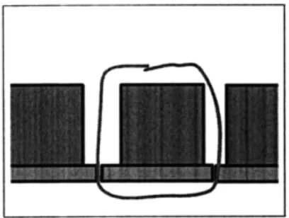
This is read "Given that a pallet (called 'pallet') exists." If there were a gesture that involved two distinct pallets, both could be referenced in this way. For example, if the forklift were to support pallet stacking only in the case that there was a filled pallet bay to either side of the pallet to be stacked, then you could specify that in StepStool as in Figure 3-6.
Notice that in Figure 3-6 three occupied pallet bays must exist next to one another, so there are three "given" statements-one per pallet bay-that assign names to each of these bays. Conditions in the gesture description body reference each of these bays by name.
3.2.6
Gesture Modifiers
The " [* ]" and " [%] " notation is used after a scenic item type name (e.g. "Pallet") to mean "each" and "average," respectively. This way, conditions like "This gesture cannot be drawn on any pallets" and "This gesture must be about the size of a pallet" can be written. In other words, writing "Pallet [*]" means that all pallets should be compared, and writing "Pallet [%]" means that the attributes of all pallets should be averaged together to build an "average pallet" and this "average pallet" should be compared against.
2Shape projection specification is a technical process described in Chapter 4. StepStool only needs to know that the shape is projected.
gesture StackPallet
given Forklift forklift given Bay bay_left given Bay bay_center given Bay bay_right given Pallet pal_center shapeof Dot, Circle referent projected forklift.load is true
bay_left leftof bay_center bay_center leftof bay_right pal_left.occupied is true pal_center.occupied is true pal_right.occupied is true pal_center approx on bay_center shape approx on pal center
end
Figure 3-6: A StepStool description specifying that pallet stacking can occur only when there is a full pallet bay to either side of the target bay.
3.3 Forklift StepStool File Example
This section describes the StepStool description file used in the forklift project (Appendix A) to enable the set of commands listed in Section 2.1. This StepStool code is divided into three parts. The first lists all the scenic items in an army supply support activity that the forklift will interact with, the second lists the shapes that can be recognized by an external shape recognizer, and the third part lists all the
gestures the forklift understands.3 The following sections describe them one-by-one by describing the syntax and meaning of each new line of code.
3
3.3.1
Scenic Item Descriptions
Each scenic item is a collection of geometric attributes. Each scenic item is implicitly given an x, y, w, and h property to describe the bounding box. Thus, none of the descriptions in this part will have position parameters. Since some scenic items (such as the Ground scenic item) only need to report their positions, their definitions will be empty.
Person Scenic
The first line of the person definition is the declaration that what is being described is a scenic item called "Person."
scenic Person
Next, velocity attributes are added to the person definition.
has vx, vy # (x,y) magnitude of velocity
Another piece of vital information is whether or not this human is being watched for visual spotting cues. We need to know this, so that when an X is drawn over a human, we can check whether a "stop attending" command was meant.
has attending # The forklift is attending this person.
Finally, we close the scenic item description.
end
This signifies that we are done adding attributes to the Person description, and are ready to move on to another description. The first and last lines will be omitted from the remaining scenic item description explanations, since the descriptions start and end the same way, aside from the specified name of the scenic item.
Pallet Scenic
The Pallet scenic item has only the attribute:
has target # boolean (1 or 0)
because for pallet-related gestures, aside from location and size, we need to know only whether it will be picked up. The target attribute is used to determine if the forklift was instructed to pick this pallet up. It will be 1 when the forklift is going to pick it up and 0 otherwise. This is used later to distinguish between the "not a pallet" gesture and the "do not pick up" command.
Ground Scenic
The ground scenic item is important for movement gestures. These gestures require that the shape be drawn on the ground. This scenic has an empty body, because only the bounding box is used. The bounding box of the ground scenic is its projection onto the camera. When a stroke falls within that bounding box, it is classified as having been drawn on the ground.
Truck Scenic
Trucks have pallets on them which the forklift can manipulate, however, those pallets are only to be lifted when the truck is not moving. The system needs to keep track of whether the truck is moving, so the only line in the truck description
is:
has moving
Forklift Scenic
The forklift scenic keeps track of the state of this forklift. It needs to know about three things: whether there is a load on the forklift's tines:
which camera the user is looking through:
has view # Which camera are we looking through?
and whether the forklift has some destination queued up:
has destinationdefined # Does it have a destination?
The "loaded" attribute distinguish "pick up" commands from "drop off" com-mands. The "view" attribute validates default gestures (see the end of this section). The "destination_defined" attribute distinguishes between "cancel path" and
"destination" commands.
Bay Scenic
These are locations in the storage area where pallets are stored. All we need to know about bays is whether they already have a pallet in them:
has occupied # Is there something in the bay?
The forklift cannot place pallets in a bay that is already occupied, so a circle on a filled bay cannot be interpreted as a "drop off" gesture.
Obstacle Scenic
The last required scenic item is the generic obstacle. This is included to enable the path gesture description (explained later) to specify that the path must intersect only the ground. The body of this description is empty because only position information is needed and this information is provided by the bounding box.
3.3.2 Shape Descriptions
Shapes are what we call user's strokes after they have been classified by using its geometric features. Like scenic item descriptions, shape descriptions are collections of geometric information. Each one has an x, y, w, and h property by default to specify the bounding box.
XCircle Shape
The XCircle is a closed region with an X through it.4 This shape is used for the
"avoid region" gesture. Similar to scenic item descriptions, the first line of a shape description is that it is a shape description named after a specific thing. In this case its name is "XCircle":
shape XCircle
Aside from the bounding box, the center and radius of the approximating circle of the region is added.
has xc, yc, r
The "c" was added to the end of the "xc" and "yc" attributes to distinguish the attribute from the "x" and "y" attributes that describe the shape's top-left corner. Finally, as with the scenic item description, the shape description is ended with the "end" keyword, signifying that this shape has no more attributes.
end
For the remaining shape descriptions, the first and last lines will be omitted, since they are the same aside from the name.
X Shape
The X shape is used to denote destination points, canceling tasks, and internal corrections, such as the "this is not a pallet" command. To be able to accurately determine the location of the X, the center (x, y) coordinate must be known. As with the XCircle, they are called "xc" and "yc" since there are already x and y attributes.
has xc, yc # Center (x,y) coordinate.
4
Though this is called "XCirlcle," the "circle" part of the XCircle does not have to be a circle, it can be any closed region.
Circle Shape
The circle is a simple combination of the center (x, y) coordinates and the radius:
has xc, yc # Center (x,y) coordinate.
has r # Radius
There is no ellipse, because a circle is general enough to use for StepStool's geo-metrical comparisons. The circle is assumed to be closed, but does not need to be strictly circular-variation is allowed. The circle is used for commands including "attend to person," "pick up a pallet," and "drop off a pallet."
O_0 Shape
The O_O shape consists of two side-by-side circles of approximately the same size. It is used to indicate where a pallet's slots are. It consists of the (x, y) coordinates of the center points of each circle, and each circle's radius:
has lx, ly, Ir # left circle (x, y, r) has rx, ry, rr # right circle (x, y, r)
The only command that looks like this shape is the FindSlots gesture.
PolyLine Shape
This is an arbitrarily squiggly line that does not define a closed region. It is used for the "path" gesture. Its description body is empty because only the bounding box is used.
Dot Shape
The dot is just an (x, y) position on the screen. It serves a similar purpose as a click would in traditional interfaces-it signifies a desired interaction with a known item. Its description body is empty, because the only needed attributes are the
(x, y) coordinates which are interpreted as the location. We can assume that the
inherited width and height will be close to or equal to 0.
-3.3.3
Gesture Descriptions
Gestures are shapes that have been recognized in the context of the scene to mean something specific. They must specify what they look like, their referent, and a list of conditions that, when met, classify a shape as that gesture.
Destination Gesture
The Destination gesture is a command to the robot to go to a specific location. This gesture consists of a dot or an X being drawn on the ground. As with the other two types of descriptions, gesture descriptions start with the keyword specifying that
it is a gesture, followed by its name:
gesture Destination
Since we know destinations must be drawn on the ground, we will add a line that says the ground must exist in StepStool's scene. We will call the ground "ground."
given Ground ground
Also, since we do not want this gesture to conflict with the CancelPath gesture, we will make sure that this command can only be issued when the forklift does not yet have a destination defined. We make sure that there is a forklift object (a state object) in the scene:
given Forklift forklift
Next, we specify that only a dot or an X can be interpreted as a destination gesture:
shapeof Dot, X
For this particular gesture, the referent is the (x, y) location on the ground where
the forklift is supposed to go. This gesture's referent is the point projected from the shape (the X or the dot) on the screen where the forklift must go.
Next the conditions under which a dot or X shape will be classified as a destination are listed. First, as stated earlier, the shape must be drawn on the ground.
shape on ground
The keyword "shape" is what is used to specify the shape being evaluated-in this case either a dot or an X. We must make sure that the forklift is not asked to drive over any pallets, people, trucks, or other obstacles:
shape not on Pallet[*]
shape not on Person[*] shape not on Truck[*] shape not on Obstacle[*]
These four lines specify this, using the "[*]" notation to specify each of a type taken individually. The English equivalent of the first line would be: "the shape is not on any Pallets." Next we specify that the forklift cannot have a destination defined:
forklift.destinationdefined is false
This constraint avoids conflicts with the CancelPath command. Finally, as with the other types of descriptions, gesture descriptions end with:
end
The first and last lines of the remaining gesture descriptions are logically the same and so will be omitted.
Path Gesture
The path gesture is very similar to the destination gesture. It differs in that the shape it takes on is a polyline instead of an X or a dot, that it issues the command to follow a series of destination points instead of just one, and it cannot be confused with the CancelPath gesture, since it does not take on the shape of an X. As a result, there are only two differences between these two gestures' descriptions. Firstly, the "shapeof" statement is different:
shapeof PolyLine
And secondly, there is no restriction that there cannot be a destination defined. The rest of the path description is identical to the destination's description since the path and destination gestures are so similar.
Discover Gestures
Pallets can be discovered in either a pallet bay or on the back of a truck. Two different discover gestures are defined to handle each of these cases. For the case of the DiscoverInBay gesture, we make sure a bay and the forklift state scenic are defined.
given Bay bay
given Forklift forklift
and we specify that this gesture looks like a circle and that its referent is the Circle projected.
shapeof Circle referent projected
The first condition we write, is that this shape must be drawn on the bay.
shape on bay
This gesture's is approximately the size of a pallet, so we use the "[%]" notation to specify that the "average pallet" should be used as the second argument to the "sizeof" condition.
shape approx sizeof Pallet[%]
And we know that the bay must not have anything in it5 and that the forklift's tines are empty, so that we can pick up the pallet once it is discovered.
5Even though there is actually a pallet in the bay, the system does not see it there, thus we write
that the pallet bay is unoccupied. It should be clear that the purpose of this particular gesture is to
bay.occupied is false forklift.loaded is false
The DiscoverOnTruck command differs by three lines involving the truck.
given Truck truck shape on truck
truck.moving is false
The first two lines are analogous to the bay conditions in the DiscoverInBay gesture. The third specifies that the truck cannot be moving.
Pick-up Gestures
Pallets can be picked up from the back of a truck or from a pallet bay by drawing a dot on or a circle around a pallet. Because of the differences between the Dot shape and the Circle shape, there are two separate gesture definitions for the "pick up that pallet" command. To start each description we make sure there is a pallet:
given Pallet pallet
Next we specify the shape. For the PickupClick, the shape is a Dot:
shapeof Dot
and for the PickupCircle, the shape is a Circle:
shapeof Circle
For both gestures, the referent of the gesture is the pallet to be picked up and the shape must be on that pallet:
referent pallet shape on pallet
We needed to separate this command into two descriptions, because when the shape is a circle, we would like the circle to be about the same size as the referent pallet. Since the dot has no area, however, it does not make sense to include this constraint in the PickupClick gesture description.
shape approx sizeof pallet
Drop Off Gestures
As with the discover gestures, we require two gesture descriptions for the "drop off"
command. These two gesture descriptions mirror the descriptions of the discover commands' aside from requiring that the pallet tines be full:
forklift.load is true
and, in the case of the DropOffBay gesture, that the referent bay is empty:
bay.occupied is false
Avoid Region Gesture
The avoid region gesture description is simple because it has only one constraint-that the shape is drawn on the ground. There are no other restrictions on where it can be drawn, how large it must be, or what it can contain, because it is the only gesture which takes on the shape of the XCircle, so there is no need to be more specific.
Attend Gestures
The attend gestures are analogous to the pickup gestures. Instead of picking up a pallet, however, a person is selected from the world and watched for cues.7 Since no pallet will be engaged, the state of the forklift does not effect the validity of the gesture (as already having a load would effect the validity of a pickup gesture). As a result, this description is shorter than the "pick up" gestures.
6
These gestures' referents are still the projected regions, because the forklift's localization module is incapable of high enough precision to place pallets accurately enough in the pallet bay or on the truck bed without a cue from the user. Here, the cue is the projection of the user's stroke.
7As previously noted, this is not implemented in the system at large, only in the interface in