A DEVICE-INDEPENDENT GRAPHICS MANAGER FOR MDL by
Poh Chuan Lim
S.B., Massachusetts Institute of Technology (1980)
Submitted in Partial Fulfillment
of the Requirements for the
Degree of Master of Science
at the
Massachusetts Institute of Technology
June, 1982
Copyright @ Massachusetts Institute of Technology 1982
Signature Redacted
Signature of Author ... ...
Department of Electrical Engineering and Computer Science
A
14 IfMay
17, 1982Signature Redacted
M19
Certified by . . . .
Albert Vezza
Signature Redacted
Thesis SupervisorAccepted by .. :...
Arthur C. Smith Chairman, Departmental Committee on Thesis
rchives
MASSACHUSETTS INSTi TUTE OF TECHNOLOGY
OCT 20 1982
A DEVICE-INDEPENDENT GRAPHICS MANAGER FOR MDL by
Poh Chuan Lim
Submitted to the Department of Electrical Engineering and Computer Science on May 17, 1982 in partial fulfillment of the requirements for the degree of Master of Science.
Abstract
This thesis describes a graphics system on which device and machine independent graphics application programs may be developed. A high level language has been extended to include a set of display management, graphics input, and graphics output functions. Display management is accomplished through a window and viewport facility. The display management functions divide the display screen into several viewports, each of which is a virtual screen on which images are displayed. The graphics input functions obtain inputs either synchronously or asynchronously from graphics input devices. The graphics output functions can draw lines, fill triangles, combine boxes, and display text on viewports. Since the basic graphics input and output functions are graphics device independent, programs that use those ftnctions to obtain input or to display images will be device independent and hence transportable.
The graphics system is also transportable because only a small isolated module in the graphics system is machine dependent or graphics device dependent. The rest of the graphics system is written in a high level language. The machine dependent module that interfaces the rest of the graphics system with a real machine and real graphics devices is modelled after Western Digital's Pascal P-code interpreter. That small interpreter module executes the machine and device independent instructions that the graphics system compiler generates. Thus, one can move the graphics system to a new machine easily since only the machine dependent module needs to be implemented for each new machine or graphics device.
THESIS SUPERVISOR: Albert Vezza
Acknowledgments
I would like to thank my thesis advisor, Albert Vezza, for suggesting the
tQpic of research, providing the motivation, funding and equipment, supervising the research, and reviewing the thesis. This thesis would not be possible without his guidance and help. Grateful thanks are also due to Professor J. C. R. Licklider for modifying my perception of computer science and computer graphics, and for helping me to improve my written English.
Many people in the Programming Technology Division, where this thesis was written, and in the neighbouring Office Automation Group provided useful assistance at various times. Christopher Reeve, one of the original implementers of the language MDL, modified the MIM compiler to compile graphics instructions, and helped in the debugging of the Motorola M68000 assembly programs. Bahram Namir's experience in implementing a general raster operation algorithm on the Motorola M68000 based Nu Personal Computer mad-. my implementation of the box operations much faster, easier, and more efficient. Ron Y. Pinter found the algorithm for decomposing a polygon into triangles, and Marc Blank clarified the conceptual design of the overall system. I have also profited from discussion on graphics with Bahram Namir and Larry S. Rosenstein, from reviews on my thesis proposal and thesis by Professor J. C. R. Licklider, Rajeev Sangal, Janet Schoof, Alexander Sen Yeh, Steve Berlin, Christopher Reeve, and S. W. Galley, and from the experience of S. W. Galley, P. D. Lebling, and Craig Lawson when they used the graphics system. The patience of my office mates -- Shlomit Pinter, Tom Michalek, and Alexander Sen Yeh -- and the cheerful disposition of several secretaries has made my burden more bearable, and my stay at the Programming Technology
Table
of Contents
Abstract... . . . .
. . . .
. . . .
2
Acknowledgements ...
3
Table of Contents ...
4
List of Figures . . . .
7
Chapter 1: Introduction and Overview of the Graphics System 1.1 -- The DIG RAM System . . . . 9
1.2 -- Background and Related Research . . . . 12
1.3 -- Outline of Thesis . . . . 14
Chapter 2: Design of the DIGRAM System 2.1 -- Design Goals. . . . . 17
2.2 -- Components of the DIG RAM System. . . . . 20
2.2.1 -- Device Interface for the Graphics System . . . . 22
2.2.2 -- Graphics Run-time Support Sub-system. . . 22
2.2.3- Display Application Package Sub-systems. . . . . 24
2.2.4 -- Device-Independent Graphics Compiler . . . . 24
2.2.5 - Graphics Order-code for Device Compiler . . . . 24
2.3 -- An Example . . . . 25
Chapter 3: The Virtual Graphics Device
3.1 -- Virtual Graphics Device Instructions . . . . 283.1.1 -- Setup Instructions . . . . 29
3.1.2 -- Query Instructions . . . . 30
3.1.3 -- Input Instructions . . . . 31
3.1.4 - Output Instructions . . . . 32
3.2 -- Displaying Images on Bit-Map Display Devices . . . . 34
3.2.1 -- Line Drawing Modes and Triangle Filling Modes . . . . 35
3.2.2
--Box Combination Modes . . . .
39
4.1- Viewports and Windows ... 44
4.2 - Viewport Manager Functions ... 47
4.2.1 - Viewport Allocator Functions. . . . . 47
4.2.2 - Viewport Modifier Functions. . . . . 48
4.2.3 - Viewport Utility Functions... . ... 49
4.3 -- Components of a Viewport...
.
.. 49
4.3.1 - Viewport Limits and Display Screens... .
...
504.3.2 - The Viewport Display Function and Object. . . . . 52
4.3.3 - Other Viewport Data
...
54Chapter 5: Basic Graphics Functions
5.1 -- Graphics Input Functions...
565.1.1 -- Input Character Translation.
...
575.2 -- Graphics Output Functions . . . . 58
5.2.1 - Line Functions . . . . 58 5.2.2 - Triangle Function
...
60 5.2.3 - Box Function....
63 5.2.4 -Text Functions. ...
64
Chapter 6: Conclusion
6.1 -Summary. ... 666.2 - Some Implementation Details ... 69
6.3 - Suggestions For Further Research. ... 71
Appendices
Appendix A - Viewport Manager Functions ....
73Appendix B - Basic Graphics Functions
...
76B.1 - Graphics Input Functions. . . . . 76
B.2 - Graphics Output Functions. . . . . 77
Appendix C - Virtual Graphics Device Instructions . . . . 79
Appendix D - Clipping a Triangle.
...
82D.1- A Technique for Clipping Triangles. ... 82
D.2 - Implementing the Clipping of a Triangle . ... 84
Appendix E -- Filling a Triangle . .... ... 88
E.1 - The Triangle Filling Operation.
...
88E.2 - Implementing the Triangle Filling Operation. . . . . 92
F.1 -- The Box Combination Operation ... 100 F.2 -- Implementing the Box Combination Operation . . . . 102
Glossary
G lossary . . . . 108
References
List of Figures
Figure 2-1 - Components of the DIGRAM System . . . . 21
Figure 2-2 - An Example of How the DIGRAM System Produces an Image . 26 Figure 3-2 - The Encoding of Four Triangle Filling Modes. ... 37
Figure 3-1 -- A Diagram for the Encoding of Line and Triangle Modes . 36 Figure 3-4 -- The Encoding of Sixteen Box Combination Modes . . . . 41
Figure 3-3 - A Diagram for the Encoding of Box Combination Modes . . . . 40
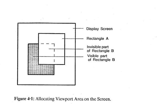
Figure 4-1 -- Allocating Viewport Area on the Screen . . . . 51
Figure 5-1 - Breaking Complex Polygons into Basic Triangles . . . . 61
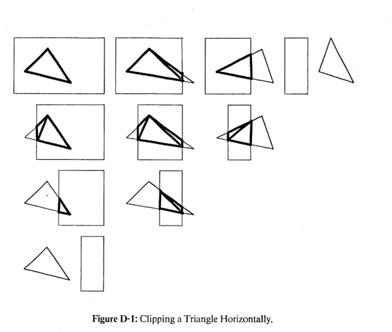
Figure D-1 -- Clipping a Triangle Horizontally . . . . 83
Figure D-2 - Routine to Clip a Triangle Horizontally . . . . 86
Figure E-1 - The Two Horizontally Based Triangles in a Triangle . . . . 89
Figure E-2 - Clipping a Triangle Horizontally . . . . 98
Figure F-1 -- Register Allocation for Box Routine . . . . 102
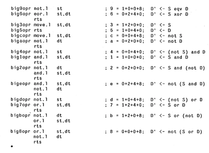
Figure F-2 - Dispatch Table and Combination Operations for Box Routine . 104 Figure F-3 - Dispatch to Various Subroutines for Box Routine. . . . . 105
To
People on the Second Floor of LCS,
Who helped and encouraged me when they could.
I would not have succeeded if not for them.
IfI have seen a little further than others
it is because I have stood on the shoulders of giants - Isaac Newton
Chapter One
Introduction and Overview of the Graphics System
1.1 The DIGRAM System
This thesis describes a graphics system on which device and machine independent graphics application programs may be developed. The application programs devejoped in such a system are portable so one need not redevelop those programs for each machine or display device on which they are expected to run. Portability is important because many different computers with graphics devices have become widely available with recent developments in the field of personal computers. Developing portable graphics application programs in this graphics system reduces the cost of transporting programs from one machine or display device to another.
The graphics system itself is also relatively portable because the machine dependent and graphics device dependent parts are isolated in a small interpreter module and the rest of the graphics system is implemented in a high level language. Our method of isolating the machine dependent parts of the system is modelled after Western Digital's Pascal P-code interpreter. The interpreter interprets the machine and device independent instructions that are generated by the graphics system compiler. Thus, the graphics system can be easily moved to several other machines by implementing only the interpreter module for each new machine or graphics device.
The Device-Independent Graphics Manager (DIGRAM) system is a portable graphics system on which portable graphics application programs can be
developed. A high level language has been extended with a set of display
management, graphics input, and graphics output functions to create this graphics system. Although the concepts developed in this thesis are applicable for any class of display devices, the DIGRAM system has been specifically designed and implemented for bit-map display devices in order to limit the effort to a manageable size. This system has been implemented by extending the language MDL. Application programs developed in the system has to be written in MDL. Most of the concepts realized in the DIGRAM system will still be applicable when a similar graphics system is implemented in another programming language, or for another class of display devices.
The DIGRAM system has been designed to use bit-map display devices efficiently. A basic bit-map display device refreshes its display screen periodically from a bit-map display memory. The bit-map display memory is usually a contiguous region of memory that stores the images that is displayed on the screen. The device organizes the display screen as a rectangular array of points, called
pixels*. A pixel can have several level of brightness. If the pixel has only two levels
of brightness, the device stores the intensity of each pixel as a single bit in a bit-map display memory. Though there are many different types of bit-map display devices, all of them are very similar to the generic device described above.
A bit-map display device was chosen for several reasons. The graphics
system is a realization of a concept. As such, some engineering trade-offs have been made to keep the realization manageable. One of these is restricting the realization to display devices, like bit-map graphics display devices, that have some common graphics capability. Every bit-map display device can test and change the intensity
of any pixel on the screen. Many bit-map display devices have other capabilities, like the ability to display lines and solid areas. Since the graphics system can easily simulate those other capabilities using these two capabilities, it can display a variety of images on these devices. Moreover, the bit-map display screen refresh rate, unlike some other display devices, is independent of the complexity of the displayed image. Thus, a well designed bit-map display can display arbitrarily complex images that are flicker-free. Finally, recent reductions in the cost of memory have made bit-map display devices cheaper and more widely available.
The language chosen for the implementation of the DIGRAM system is MDL (originally called "MUDDLE"). The language MDL1, 2 is derived from the language LISP, and first appeared in the early 1970's in the MIT Laboratory for Computer Science and the MIT Artificial Intelligence Laboratory. In 1979, a project to redesign and reimplement the MDL language processor began. In that project, the MDL interpreter, compiler, and environment were rewritten so that they are all machine independent except for a small low level kernel. The aim of the project was to allow MDL programs to move to a new machine quickly and easily. The DIGRAM system is an extension of this effort to create portable software.
The language MDL was chosen because the goals of the Machine Independent MDL (or MIM) project are compatible with the goals of the graphics system. Moreover, a virtual machine instruction interpreter, and a compiler for this virtual machine's instructions already exist for MDL. The language is also interactive so debugging MDL programs is easy. In addition, several projects on graphics have already been carried out in the language MDL:
-Gregory F. Pfister (one of the original builders of MDL) wrote a
doctoral thesis -- The Computer Control of Changing Pictures3 -- in which he discussed the implementation of DALI, a sublanguage of MDL, to provide a better control of graphics images in MDL.
- Richard R. Shiffman later created the MUDDLE Interactive Graphics
System (or MIGS). MIGS ran on the Imlac graphics terminals at the
Programming Technology Division of the Laboratory for Computer Science.
The graphics projects mentioned above have provided MDL with a graphics programming tradition. Thus, the graphics system described in this thesis is a natural extension of prior research with the introduction of the concepts of portability and viewports to MDL. The DIGRAM system also allows MDL programs to use bit-map graphics display devices conveniently.
1.2 Background and Related Research
This section describes some of the research carried out elsewhere that is related to the graphics system research reported in this thesis.
The design of the portable graphics system is modelled after the design of the MIM language processor, and Western Digital's design of the Pascal language processor using P-code. Those language processors have been made portable by isolating the machine dependent parts of the language in a module. This module is, conceptually, an interpreter for instructions of a virtual machine. Basically, one chooses a higher level language and a small low level virtual machine, creates a compiler that compiles programs in that language to run on the virtual machine, writes the compiler and run-time system in that language, and compiles the compiler and the run-time system for that virtual machine. Thus, implementing the compiler aid the run-time system for a new computer is unnecessary if the small virtual machine can be implemented on that computer. A program in the language can run on any computer that simulates the virtual machine, and that small virtual machine is easier to implement than a large compiler or run-time system.
Although the idea of storing images in a bit-map display memory and refreshing the display screen by raster scanning the display memory regularly is not a new idea, the high cost of fast memory has made devices that use this idea commercially impractical until recently. Researchers in computer graphics have implemented several graphics projects that use bit-map display devices. For example,
-R. F. Sproull and some others at Xerox PARC were working on the
ADIS project4 to produce a graphics package for the Interlisp-D -- also known as DLISP -- programming language.
-Researchers at Xerox PARC have developed the Smalltalk5,6,7 interactive computer language. Smalltalk has a graphics capability.
-J. Eugene Ball at Carnegie-Mellon University was developing the AT
(Alto Terminal) package to enable a C program running on a Vax-Unix system to use the Alto personal computer as a terminal.
-Researchers at Bolt, Beranek and Newman Inc. were building a bit-map display device called Jericho.
-Researchers at Bolt, Beranek and Newman Inc. were working on the
Bit-Map Graphics (also known as BMG) project to provide a graphics
interface for the AIPS9'10,11 (Advanced Information Presentation System) project.
-Researchers at the MIT Artificial Intelligence Laboratory were developing the Lisp Machine12,13. The Lisp Machine has a bit-map display device.
Several features in the graphics systems developed in the projects mentioned above are also found in the DIGRAM system. For example, many researchers have discovered that raster operation** is useful, that operations to
display text are essential, and that the ability to divide the display screen into several independent areas is convenient. However, the DIGRAM system also has functions to draw lines and triangles, and a systematic design for the graphics output fmnctions. The systematic design makes graphics output functions easier to use, understand, and remember.
Some other research in computer graphics is also related to the design of this graphics system. Ivan Sutherland, one of the early researchers in this field, investigated the use of interactive computer graphics in the SKETCHPAD project14 in the early 1960's. He concluded that communication with computers using interactive computer graphics was simpler and quicker than by more conventional methods in use at that time. Much research into the use of interactive computer graphics has been carried out since then, and W. M. Newman and R. F. Sproull, in their book Principles of Interactive Computer Graphics,15 summarize many important ideas and issues that researchers in this field have encountered.
The Graphics Standard Planning Committee (GSPC) of the ACM Special Interest Group on Graphics (SIGGRAPH) is developing a graphics standard16 based on their Core Graphics System17'1 to increase the portability of graphics programs. However, that graphics standard is based on the vector graphics display device rather than the bit-map graphics display device. Therefore, that standardization effort is related to the proposed graphics system in only a very peripheral way.
1.3 Outline of Thesis
The second chapter outlines the overall graphics system. The first section states some of the desired goals of the graphics system and how the graphics system
may achieve those goals, the second section briefly describes the five components of the graphics system, and the last section shows a simple example of how the graphics system displays an image on a display screen.
The third chapter describes the graphics device dependent module of the graphics system. This module is an interpreter for the instructions of a virtual graphics device. The first section categorizes the instructions in the virtual graphics device, and the second section describes an interesting way of organizing some output instructions systematically and conveniently for a bit-map display device.
The fourth chapter describes the organization of the display screen. The first section explains the concept of viewports and windows, the second section categorizes the operations on viewports, and the third section provides some more details about the viewports used in the graphics system.
The fifth chapter describes some of the basic graphics functions that graphics application programs can call to use a graphics device. The first section describes the graphcs input functions, and the second section describes the graphics output functions. The graphics system can have other basic graphics functions as well since the overall design of the system does not limit the basic graphics function only to those stated in chapter five.
The last chapter briefly summarizes the discussion in the previous five chapters, and explains how the system was implemented. That chapter also has some suggestions for subsequent extensions to the graphics system, and further research in this area.
Other less interesting details of the graphics system have been left in the appendix. The appendix has a glossary of the graphics terms used in the thesis, and
lists the virtual graphics device instructions, the viewport manager functions, and the basic graphics functions. The appendix also describes the implementation of the triangle filling operation and the box combination operation. Those details are located in the appendix because they are implementation dependent and hence would differ for different systems.
Chapter Two
Design of the DIGRAM System
A brief outline of the Display Independent Graphics Manager (DIGRAM)
system is given in this chapter. Some of the design goals of the DIGRAM system are stated in the first section. A rough outline of the design of the DIGRAM system is given in the second section. A simple example to illustrate how the various components of the DIG RAM system interact is presented in the last section.
2.1 Design Goals
Several goals are incorporated in the design of the DIGRAM system. These goals and how they affect the design of the overall system are discussed below.
The first goal of the DIGRAM system is to ease the development of portable graphics application programs. Thus, similar programs that make use of different graphics devices will not have to be rewritten.
The second goal is to design a portable graphics system. Thus, the graphics support software will not have to reimplemented for different devices.
This goal can be achieved by designing a virtual graphics device with a minimal set of capabilities for which application programs and the graphics support software can be written. The virtual device instruction interpreter interprets the virtual graphics device instructions. The virtual device instruction interpreter has to simulate each of the graphics capabilities in the virtual graphics device not available
on a real device. This simulation is possible only if all the real devices have a small common set of graphics capabilities.
There are several graphics device parameter values, like the height and width of the screen, that are device dependent. The virtual device can provide those parameter values to a device independent program at run-time. The program will run slightly slower since those parameter values are not known at compile time but then that is a small price to pay to achieve portability. Another compiler specifically for a frequently used graphics device may be written to accommodate users who need a faster program.
The third goal is to prevent the output of two or more programs on one screen from interfering with one another. For example, the debugging of a graphics application program on a computer with only one output display device is difficult since the output of other programs can easily interfere with the output of the graphics program on the screen. Hence, debugging a program interactively is much easier if the output of the application program and the debugging program can be examined separately. Moreover, there are occasions when the user wants to compare the output from several programs visually. The display output should be organized so that when this occurs, the images are displayed properly.
One way of organizing images on the screen is to use the concept of virtual screen which is similar to the concept of virtual memory in operating systems. The concept of virtual memory and memory protection allows the sharing of a limited resource, namely, the primary memory, among several programs. Each program has full access to its virtual memory but cannot access the virtual memory of any other program. Similarly, the concept of a virtual screen, or a viewport, allows the sharing of a limited resource, namely, the display screen, among several programs. Each program has full access to its own viewport but cannot access the viewport of any
other program. Image protection will prevent other programs from damaging the output of a given program. Thus, a graphics application programmer can debug a program easily since any defects in the displayed image can be attributed solely to that program.
There is another advantage of using the concept of a virtual screen to organize images. Each program displays its images on only a part of the display screen. Each image displayed on the screen is smaller when the virtual screen concept is used than when it is not used. Thus, a program can display images more quickly in a graphics system that uses this concept.
The fourth goal is to have a modular design for the DIGRAM system. A large system like the DIGRAM system can be built more easily if the divide and conquer strategy is used to decompose the overall system into smaller sub-systems that can be implemented separately. Furthermore, the modular design of DIGRAM allows for additions to it, and evolution of it. Capabilities likely to be added at a later date are, for example, the graphics input system, or the sub-system for vector graphics functions.
Finally, the graphics system should have a general design that supports a wide variety of application programs. The graphics system will make very few assumptions about the nature of any application program that will use it since it may be used to implement many different programs.
The graphics system will support this goal in two ways. It will not modify the region within a virtual screen, or viewport, of the graphics application program. For example, the DIGRAM system will not put a border around any viewport because some programs support viewports that do not have a border while other programs support viewports that have a special type of border. Each program will
have to draw a suitable border in its viewports if a border is desired. Since many
different types of images may be displayed in a viewport, the program will have to
store the contents of its viewports. The graphics system updates the display screen
when the viewport area changes by calling the redisplay function that the
application program provides.
Some of the objectives of the DIGRAM system have been stated above.
They have influenced our design decisions regarding the proposed system. An
outline of the DIGRAM system is given below.
2.2
Components of the DIGRAM System.
The DIGRAM system is similar to the system implemented in the MIM
--Machine Independent MDL --
project at the Programming Technology Division of
the Laboratory for Computer Science. The interactive portion of the DIGRAM
system has three main components arranged in a hierarchical order.
These
components are the Device Interface for the Graphics System (DIGS), the Graphics
Run-time Support Sub-system (GRSS) which is compiled to DIGS virtual device
instructions and MIM virtual machine instructions, and the Display Application
Package Sub-systems (DAPS) which is written in MDL and GRSS. There are three
categories of graphics programmers and users. At the lowest level, the graphics
system designer designs and implements DIGS and GRSS, and adapts DIGS to new
display devices. Then there is the DAPS writer who writes several DAPS using
GRSS and MDL. And finally, there is the DAPS user who uses those DAPS
programs. In addition, there are two compilers -- DIGCOM and GODCOM -- tocompile DAPS and GRSS programs written in MDL to run on the DIGS virtual
Device Independent Device Dependent DAPS MDL Interpreter GRSS DIGCOM DIGS GODCOM Display Device KEY DAPS GRSS DIGS DIGCOM GODCOM (MDL Program) (GRSS Instruction Interpreter)
(Virtual Graphics Device Instruction Interpreter)
(Real Graphics Device Instruction Interpreter)
- Display Application Package Sub-systems - Graphics Run-time Support Sub-system - Display Interface for the Graphics System
- Display Independent Graphics Compiler - Graphics Order-code for Device Compiler Figure 2-1: Components of the DIGRAM System.
The following are the five components of the DIGRAM system.
-Device Interface for the Graphics System (DIGS)
-Graphics Run-time Support Sub-system (GRSS)
-Display Application Package Sub-systems (DAPS)
- Device-Independent Graphics Compiler (DIGCOM)
-Graphics Order-code for Device Compiler (GODCOM)
Figure 2-1 illustrates the relationship between the five components of the DIGRAM system. These components are described in more detail below.
2.2.1 Device Interface for the Graphics System
The Device Interface for the Graphics System (DIGS) is an interface between the low-level virtual graphics device on which GRSS can be implemented and a real graphics device. DIGS has a virtual graphics device instruction
interpreter to execute those device independent parts of the DIGRAM system that have been compiled by DIGCOM. A DIGS instruction interpreter is written
specifically for each real graphics device. That instruction interpreter will simulate any virtual graphics device instructions that are absent from the real graphics device and will translate those instructions that are present on the real graphics device. The
DIGS instruction interpreter can be considered as an extension of the MIM
instruction interpreter that can interpret display instructions as well.
2.2.2 Graphics Run-time Support Sub-system
The design of the Graphics Run-time Support Sub-system (GRSS) was influenced by the design of the Core Graphics System.17' 18 The Core Graphics System is the result of the recent efforts by the Graphics Standard Planning
Committee (GSPC) of the ACM Special Interest Group on Graphics (SIGGRAPH) to develop a graphics standard16. A few additional features have been added to this design to take advantage of the special characteristics of bit-mapped display devices and to enforce the concept of image protection within a viewport.
GRSS, embedded in the language MDL, supports a set of functions that DAPS programs use to manipulate graphics input and output devices in a systematic
manner. These functions can be roughly divided into two categories:
- Viewport Manager Functions: These functions manage viewports,
redisplay the screen, update the database for viewports, and allocate different regions of the display screen to different viewports.
- Basic Graphics Functions: These functions obtain input from input
devices and produce images on display devices. The application program can display lines, triangles, boxes, and text with output functions. The output functions also enforce image protection for the graphics system. Other functions set up defaults for the graphics system, provide an on-line help facility, and provide some information on the graphics device (eg. the height of the screen) at run-time.
Thus DAPS writers will be able to use GRSS and MDL to write their DAPS programs without having to worry about device dependent issues or the damaging of an image in a viewport by other programs.
GRSS is initially compiled to run on the DIGS virtual display. Thus, GRSS is device independent. A DIGS interpreter is used to execute GRSS
procedures and functions. The GODCOM compiler, if available, can be used to compile GRSS so that GRSS can run more efficiently on a specific display device.
2.2.3 Display Application Package Sub-systems
The Display Application Package Sub-systems (DAPS) writer uses GRSS and MDL to write DAPS programs. These DAPS may include programs to create three dimensional images, draw graphs, provide an interactive graphics editor, or run a text editor.
Each DAPS program is first written in MDL and GRSS and debugged interactively. Later, when production programs are needed, the DAPS programs may be compiled using DIGCOM to DIGS instructions, which can run on the
DIGS virtual device. To increase the speed and efficiency of a DAPS program, GODCOM may be used to compile the DAPS program to run on a specific real
graphics device.
2.2.4 Device-Independent Graphics Compiler
The Display-Independent Graphics Compiler (DIGCOM) can be used to compile DAPS programs written in GRSS and MDL to DIGS instructions which will run on the DIGS virtual display. The compiled DAPS program runs much faster than the interpreted DAPS program since the overhead due to interpreter calls is bypassed. DIGCOM also improves the speed of the code generated for the compiled DAPS in other ways. The software for GRSS is initially written in MDL and is compiled using DIGCOM to DIGS instructions so that GRSS can run on the
DIGS virtual device. Thus, DIGCOM can be considered as an extension of a MDL
compiler that compiles instructions for graphics devices as well.
2.2.5 Graphics Order-code for Device Compiler
The Graphics Order-code for Device Compiler (GODCOM) can compile
graphics device, bypassing the DIGS interpreter. This compiler is written specifically for a graphics device, and is able to understand and make full use of the features of that graphics device.
2.3 An Example
A simple example can illustrate how the various components of the
DIGRAM system interact to generate an image on the screen of a display device. In this example, a line is drawn on the screen and Figure 2-2 shows how each component of the DIGRAM system affects the final image on the screen.
Let us assume that the user runs a DAPS program that displays an image. An example of such an image may be a line. To draw this line on the display screen, the DAPS program calls the line drawing GRSS function with the endpoints of this line, a viewport to draw this line, and the mode to draw this line as arguments. The DIGRAM system takes over from here and eventually displays the clipped image on the display screen.
The GRSS viewport manager maintains a list of active viewports and allocates a different area of the display screen to each viewport. This viewport manager also restricts the allocation of viewport areas so that the viewport areas allocated do not overlap. When a program displays an image on a viewport, the viewport indicates the area on the screen where the image may appear. GRSS ensures that all the viewports in the graphics system are consistent while DIGRAM is running.
When a program calls a GRSS graphics outputfunction, that function clips the image so that the resultant image is totally within the given viewport area. Then, the GRSS function draws the clipped image on the display device by calling the
DAPS wants to draw a line.
GRSS
Viewport Manager Functions manages viewport showing the line.
GRSS
Output Functions clips the line.
DIGS
Line Instruction draws the line on the screen.
Figure 2-2: An Example of How the DIGRAM System Produces an Image.
appropriate DIGS instruction. Thus, GRSS enforces image protection by clipping the image so that the display screen displays only the portion of the image within a given viewport.
The DIGS instruction interpreter interprets a virtual device instruction by calling the appropriate instruction on a real graphics device to display the image on the device screen. If the real graphics device does not have an instruction to display the image on the screen, then the image displayed is simulated using other instructions. For example, if a program would like to display a line but the real device does not have a line drawing instruction, then the DIGS instruction interpreter simulates a line by a sequence of points. Only the portion of the image in the viewport area is visible on the screen since GRSS has already clipped the image.
The above description of the DIGRAM system behavior applies when any application program displays any image on a viewport. The process is reversed when a program obtains graphics inputs. DIGS obtains and then sends the input to
GRSS. GRSS then filters and scales the graphics input so that DAPS can use the
input easily. GRSS maintains and provides any defaults like a suitable scaling factor or a filter factor. Since only DIGS interacts with the real graphics device, all the graphics software except for DIGS is device independent and hence transportable.
GRSS enforces image protection and provides functions that make the writing of DAPS programs more convenient. This, then, is a brief description of how the
Chapter Three
The Virtual Graphics Device
This chapter describes the device interface for the graphics system. The
DIGS sub-system interfaces the graphics software with a real bit-map display by
presenting a virtual display to graphics programs. This sub-system also interfaces the graphics software with graphics input devices. A systematic manner of encoding images displayed on a bit-map display is also presented in this chapter.
3.1 Virtual Graphics Device Instructions
The virtual graphics device makes operations on a real graphics device available to a program in a systematic, device independent manner. The virtual device provides four types of instruction, namely, setup instructions, query instructions, input instructions, and output instructions. Those instructions are described in this section.
The main aim of the virtual graphics device is to provide a clean interface between a real graphics device and the graphics software. To achieve this goal, a consistent protocol that links MDL programs with the virtual device is designed.
That protocol -- a stack machine calling mechanism -- allows every MDL program
to use a real graphics device by pushing arguments on the stack and then executing a virtual device instruction. The virtual device's instruction interpreter invokes the appropriate real graphics device operation, or invokes several other real graphics device operations to simulate the virtual device instruction if the real device does not support that operation. Since there is a consistent device independent protocol
to invoke a real graphics device operation from MDL, the graphics software is portable.
3.1.1 Setup Instructions
A program calls a setup instruction to obtain or return a graphics device or
resource. Some setup instructions obtain a real graphics device from the operating system for the exclusive use of the program. Other instructions return a graphics device to the system when the program no longer needs that device.
Before a graphics application program can use a display screen, the program has to obtain permission to use that device. The program calls setup instructions to borrow the display screen at the beginning and return the display screen at the end. The program that has borrowed a display screen can display images on that device. If several display screens are available, the program may want to borrow and return different display screens at different times. The setup instructions allow each program to do so in a device independent manner.
A program can also load fonts into a display device or dump fonts out of a
display device. The program can display text in several fonts if different fonts are loaded. However, the display device may not be able to hold all the fonts a program uses. Dumping unnecessary fonts will free up space for the display device to load other useful fonts. A program can load and dump fonts by calling the appropriate setup instructions.
A program that expects an asynchronous input from an input device
should enable that device for interrupts. Enabling an input device informs the operating system that the program is willing to handle interrupts from that input device. Enabling only certain input devices will also ensure that other uninteresting
input devices will not interrupt the program. When an asynchronous input is no longer needed, the input device can be disabled. Thus, a graphics application program can obtain a more imaginative response from the user by tailoring its own input with suitable setup instructions.
3.1.2 Query Instructions
The graphics system has to know several facts about each graphics device to use that device effectively. If those facts are compiled into the graphics system, then the system will have to be modified for each new device. Those facts should be stored only in the virtual device instruction interpreter. The graphics system can obtain the information from the virtual device at run-time. Thus, only the virtual device instruction interpreter has to be different for different graphics device. The application program may run slightly slower but this is a small price to pay for portability. The slow down will not be substantial since the graphics program can obtain and store each datum only once during initialization.
Most display screens have different horizontal size, vertical size, and resolution. Those device dependent facts should be made available to the graphics program through the virtual graphics device's query instructions. The graphics system can use this information to tailor each programs to use any display screen. Thus, the whole display screen may be used efficiently.
Many graphics display devices provide instructions for displaying text anywhere on the screen. A program that displays text may need to know the width and height of each character. This font information is usually device dependent. The graphics system and every application program can be device independent only if those facts are located in the virtual graphics device.
3.1.3 Input Instructions
The graphics system can receive two different types of input, namely, synchronous input and asynchronous input. Synchronous input is obtained by a graphics application program when it requests an input. Asynchronous input is input that can occur at any point of the program's execution. In this instance, the program is signalled by an interrupt from an input device. It typically will halt its normal execution and handle the interrupt. These two fundamentally different ways of interacting with the user is discussed below.
A graphics program can obtain a synchronous input from a graphics input
device by executing the appropriate DIGS instruction. The virtual input device will obtain and return the input from the corresponding real input device. Three examples of virtual devices that can generate synchronous inputs are described below:
Valuator This device is used to specify an analog value. It is a one dimensional device that generates a single floating point number between 0.0 and 1.0. Examples of valuator devices are control dials and slide rheostats.
Locator This device is used to specify a location on a display screen. It is a two dimensional device that generates two floating point numbers between 0.0 and 1.0 corresponding to the X and Y axis on the screen. Examples of locator devices are data tablets, touch pads, joysticks and mouse devices.
Keyboard This device is used to generate alphanumeric input. The user is
probably familiar with this input device since it is modelled after the typewriter keyboard and almost every terminal has some form of keyboard input device. This device buffers the characters typed in and returns the numeric code for the characters typed on the keyboard in order, or a special value if the buffer is empty.
A program may use these input devices with the asynchronous input
devices to obtain a more useful input.
Asynchronous interactions are more difficult to handle than synchronous interactions. An interrupt occurs whenever the user activates an asynchronous input device. The MDL interrupt system traps, queues, and handles this interrupt just like any other MDL interrupt. Thus, the program has to enable the interrupt for an asynchronous input device before it can obtain inputs from that device.
Two examples of devices that can generate asynchronous inputs are the keyboard and the button. The actions of these devices will be described below:
Keyboard The keyboard device is used to obtain alphanumeric data. If the
asynchronous keyboard device is enabled, an interrupt will occur whenever a key is depressed and the graphics program may process the character typed in immediately.
Button The button device is in many ways like the keyboard device.
Whenever a button is depressed, an interrupt occurs. However, the button is usually located on a pointing device like a mouse, each button does not represent any special symbol or character, and the device usually can generate only asynchronous inputs.
The interrupt handler for an asynchronous input device may obtain synchronous input values. For example, when a button is activated, the interrupt handler may sample the locator device and perhaps place a mark on the screen. The graphics program may use a combination of asynchronous and synchronous input to create a more flexible and powerful user interface.
3.1.4 Output Instructions
The virtual graphics device's output instructions allow the user to create or change images on a display screen. The virtual graphics device instruction
interpreter calls the appropriate display device routine to perform the operation. If the real display device cannot perform that operation, then the virtual device will simulate the desired display operation using other display operations.
The virtual graphics device supports four different types of outputs, namely, line, triangle, box, and text. There is a DIGS instruction for each type of output operation. Each of those operations can affect the display screen in several ways depending on the mode in which the instruction is called. One way of enumerating the modes for those operations in the virtual device is given in the next section.
The DIGS line instruction draws a line on the display screen. For a display screen that shows each pixel in only two intensity levels of one colour, the line can be drawn in four different modes. Those four modes are black, white, inverse of
background colour, and same as background colour. The line instruction accepts as arguments the two end points of the line, the mode in which to display the line, and the display screen on which the image is to appear.
The DIGS triangle instruction draws a triangle on the display screen. For a display screen that shows each pixel in only two intensity levels of one colour, the triangle can be drawn in four different modes. These four modes are black, white, inverse of background colour, and same as background colour. The triangle
instruction accepts as arguments the three vertices of the triangle, the mode in which
to display the triangle, and the display screen on which the image is to appear.
The DIGS box instruction places the result of combining corresponding pixels in two similar rectangles on the screen in one of the rectangles. For a display screen that shows each pixel in only two intensity levels of one colour, the two rectangles can be combined in sixteen different modes. The box instruction accepts
as arguments the locations of the top left corners of the two rectangles, the heights and widths of the rectangles, the mode in which to combine the two rectangles, and the display screen on which the two rectangles are located.
The DIGS text instruction displays a line of text on the display screen.
With this instruction, the graphics system can use the built-in text displaying capability of display devices. The text instruction accepts as arguments the starting position of the text to be displayed, the text to be displayed, the number of characters in the text to be displayed, the font type, and the display screen where the text is to be displayed. This instruction can probably be written in terms of either line or box instructions if an appropriate font database exist to create characters using line or box instructions.
A graphics application program can produce a wide variety graphics
images with only those four instructions. Those four instructions are very flexible because each instruction can operate in several different modes. The modes can be systematically encoded so that all conceivable line, triangle and box shades can be generated. The next section will outline a scheme whereby all possible ways of drawing lines, filling triangles and combining boxes is encoded in a suitable mode.
3.2 Displaying Images on Bit-Map Display Devices
The graphics system can easily simulate the virtual device's line, triangle and box instructions in a bit-map display device. A bit-map display device maps each bit in a bit-map display memory to a pixel on the display screen. This bit-map display
memory is usually an array of integers. A bit-map display device can also map
several bits from several different bit-map display memories to the same pixel. Each bit-map display memory is then called a bit-plane. The device may map each bit of
a bit-plane to a specific colour or a specific intensity level for each pixel.
The virtual device can treat an integer array as a virtual display screen. If the array is displayed on a real display screen, then any image stored in that-array will be visible. With this arrangement a program can easily display images on more than one real display screen. A program can transfer images on a virtual display screen to another smaller integer array and use those images later. A program can also place images in any integer array and then display that array on a real display screen. If a program uses two arrays, it can present an animated sequence by modifying one array while displaying the other array, and switching the roles of the two arrays periodically. Moreover, a program can modify each bit-plane of a display screen separately to generate overlapping images in several colours or shades. Thus a properly organized bit-mapped display device can be a very flexible and powerful display tool.
Smalltalk7 uses a very simple scheme to encode all possible raster operations in a bit-map display with a single bit-plane. The DIGRAM system uses a similar scheme to encode all the ways of drawing lines and filling triangles. The schemes to systematically encode the modes for the line, triangle, and box instructions are presented in the two sections below.
3.2.1 Line Drawing Modes and Triangle Filling Modes
When the triangle instruction draws a triangle on the screen, it changes the intensity of some pixels on the screen so that the triangle can be seen. For example, the triangle instruction can change a triangular region on the screen to white or black so that the triangle is visible. The triangle instruction can also invert the intensity of the images in the triangular region to make that region visible. Thus, the triangle instruction can display a triangle in several different ways.
Old Pixel States New Pixel States
j Mode 0 % Model1
Q Mode 2
- Mode 3 E
Figure 3-1: The Encoding of Four Triangle Filling Modes.
The different ways that the triangle instruction can display a triangle can be listed for convenience. For a display device that can display each pixel in only two shades, namely, black and white, the images on the screen can only have two intensities. Figure 3-1 is a state diagram that shows how the new intensity of each pixel in the triangle is related to the original intensity of that pixel. The triangle instruction can display each triangle in only four different ways, namely, the three mentioned in the previous paragraph, and no change to the screen, if the triangle instruction changes the intensity of each pixel in the triangle based only on the old intensity of that pixel.
Figure 3-1 also associates a numeric code with each way of filling a triangle. This numeric code can specify compactly the mode in which the triangle instruction draws a triangle. Having several instructions to draw different triangles is also unnecessary if one triangle instruction can draw triangles in different modes.
Each of the four different ways of filling a triangle is called a
trianglefilling
mode.Old Pixel States New Pixel States
-- Mode n 2 1
n = Sum of integers for white pixels.
Figure 3-2: A Diagram for the Encoding of Line and Triangle Modes.
Figure 3-2 shows a diagram that encodes the numeric codes for the triangle
filling
modes compactly. A numeric code can be found by adding all the entries inFigure 3-1 corresponding to old pixel shades that the triangle instruction will change to white. For example, the triangle instruction draws a black triangle when the numeric code is 0 because the pixel value is never white. The triangle instruction does not change any pixels when the numeric code is
1
because the new pixel value is white if and only if the old pixel value is white. The triangle instruction inverts the shade of the pixels within a triangle when the numeric code is 2 because the new pixel value is white if and only if the old pixel value is not white. The triangle instruction draws a white triangle when the numeric code is 3 (= 2 + 1) because the new pixel value is always white. Thus, both entries have to be added. The numeric codes calculated in Figure 3-2 can be compared with the numeric code shown in Figure 3-1.Only four triangle filling modes can exist on a screen that can display only two shades because each of those four triangle filling modes correspond to a boolean function of one variables. What Figure 3-2 actually illustrates is a systematic means
of mapping the numeric code of a triangle filling mode to a boolean function of one variables. Each numeric code is an integer that can be systematically mapped to a ftnction of one variable. Each function of one variable maps the old intensity of a pixel to the new intensity of that pixel. The triangle instruction uses that function to change the old intensity of each pixel in the triangle a new intensity.
Numeric codes for triangle filling modes can be specified for a screen that can display several shades or colours if all the possible ways the triangle instruction can change the intensity or colour of the pixels on the screen can be enumerated. Thus, a triangle filling mode associates an integer with a function of one variable. The triangle instruction uses that function to change the pixels in a triangle.
Similarly, the line drawing modes may be used to specify the type of lines drawn by the line instruction. The line drawing mode associates an integer with a function of one variable. The line instruction uses that function to change the intensity of each pixel on the line. Since the line drawing modes are similar to the triangle filling modes, the mapping from numeric codes to boolean functions are the same for both the line instruction and the triangle instruction.
An application program can use the modes to specify the shade of the line or triangle it displays. For example, when a program draws a white line on the screen, the program calls the virtual graphics device's line instruction with 3 as the numeric code for the line drawing mode. The virtual graphics device draws a white line on a real display screen. The program might erase that line by drawing a black line over the white line. The program does this by calling the virtual graphics device's line instruction with 0 as the numeric code for the line drawing mode. Thus, a program can use different modes of operation of the line instruction to display images with lines, and different modes of operation of the triangle instruction to display images with triangles.
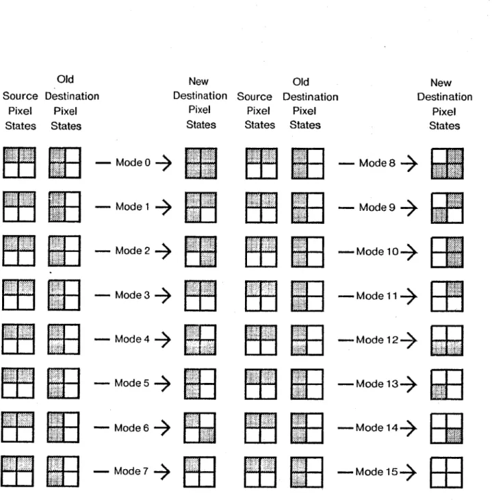
3.2.2 Box Combination Modes
The box instruction uses the box combination modes to specify how two rectangular areas on the screen of the same size and shape are to be combined. When the box instruction combines two boxes on the screen, the box instruction changes the intensity of each pixel from the destination box to the value obtained by combining the intensity of the corresponding pixel from the source box, and the old intensity of that pixel from the destination box. For example, the new image in the destination box is the inclusive or of the image from the source box and the destination box if the combine operation is inclusive or. Thus, the destination box will have the image of both the source box and the destination box since at any point in the destination box where either the old destination image or the source image in the corresponding source box is white, the new destination box is white.
However, the box instruction can combine the images in the source and destination boxes in other ways. For example, the box instruction may exclusive or the images in the source and destination boxes. The box instruction may copy the image from the source box to the destination box. The box instruction may also and the images in the source and destination boxes. Thus, a box instruction can
combine two boxes in several different ways.
The different ways that the box instruction can combine two boxes can be listed for convenience. For a display device that can display each pixel in only two shades, namely, black and white, the images on the screen can only have two intensities. Figure 3-1 is a state diagram that shows how the new intensity of each pixel in the destination box is related to the original intensity of that pixel and the intensity of the corresponding pixel in the source box. The box instruction can combine two boxes in only sixteen different ways if the box instruction changes the intensity of each pixel in the destination box based only on the old intensity of that
Old Source Destination Pixel Pixel States States
w
ER
ER
ER
ER
ER
ER
ER
- Mode0 - Mode1 - Mode 2 Mode 3 4 -Mode 4 4 Mode 5 4 -Mode 6 - Mode 7 4 New Old Destination Pixel Stateso:i
Lii
ER
ER
ER
ER
ER
ER
ER
Source Destination Pixel Pixel States StatesER
ER
ElR"
r
ER
X
ERmn
New Destination Pixel States -Mode84 - Mode 9 4 -Mode 10-> -Mode 11 4 -Mode 12-> -Mode 13-> - Mode 14-> - Mode 15->Figure 3-3: The Encoding of Sixteen Box Combination Modes.
pixel and the intensity of the corresponding pixel in the source box.
Figure 3-3 shows how the state of the intensity of each pixel changes for each way of combining two boxes. Each square in the state diagram represents a
Lii
ER
ER
ER
ER
ER
ER
ER
LU
ER
ER
ER
EEl
ER
ER
ER
possible intensity of the source pixel, the old intensity destination pixel, or the new intensity of the destination pixel. For example, mode 7 shows the inclusive or operation. When either the source square or the corresponding destination square is white, the result square is white. Thus, there is only one black square in the top left corner corresponding to a black square at both the source and destination. As another example, mode 6 shows the exclusive or operation. When the source and the destination square is opposite in shade, the result square is white. Thus, the top right square and the bottom left square is white because the corresponding square in the source and the destination differ. That figure has listed all the possible binary boolean functions. Thus, only sixteen binary boolean functions can exist.
Figure 3-3 also associates a numeric code with each way of combining the intensities of the pixels in two boxes. This numeric code can specify compactly the mode in which the box instruction combines two boxes. Having several instructions to combine boxes is also unnecessary if one box instruction can combine boxes in different modes. Each of the sixteen different ways of combining two boxes is called
a box combination mode.
Old New
Source Destination Destination
Pixel Pixel Pixel
States States States
-Mode n
n = Sum of integers for white pixels.