Diffusion-bonded CNT carpets for fundamental CDI studies
The MIT Faculty has made this article openly available. Please sharehow this access benefits you. Your story matters.
Citation Enright, R., R. Mitchell, H. Mutha, C. Lv, M. Christiansen, C. V.
Thompson, and E. N. Wang. “Diffusion-bonded CNT carpets for fundamental CDI studies.” MRS Proceedings 1407 (January 12, 2012). Copyright © Materials Research Society 2012
As Published http://dx.doi.org/10.1557/opl.2012.707
Publisher Cambridge University Press
Version Final published version
Citable link http://hdl.handle.net/1721.1/79782
Terms of Use Article is made available in accordance with the publisher's
policy and may be subject to US copyright law. Please refer to the publisher's site for terms of use.
Mater. Res. Soc. Symp. Proc. Vol. 1407 © 2012 Materials Research Society DOI: 10.1557/opl.2012.
Diffusion-bonded CNT carpets for fundamental CDI studies
R. Enright1,2, R. Mitchell1, H. Mutha1, C. Lv1,3, M. Christiansen1, C. V. Thompson1, and
E. N. Wang1
1Department of Mechanical Engineering, Massachusetts Institute of Technology, 77
Massachusetts Avenue, Cambridge, Massachusetts, 02139, U.S.A.
2Stokes Institute, University of Limerick, Limerick, Ireland 3Tsinghua University, Beijing, China
ABSTRACT
Uncertainty about future energy and water supplies suggests a pressing need to develop efficient technologies for water desalination. Capacitive deionization (CDI), a method that captures ions in the electrical double layer (EDL) of an electrochemical capacitor, is a promising technology that can potentially fulfill those requirements. Similar to supercapacitors, ideal CDI electrodes should have a large electrolyte-accessible specific surface area available for ion adsorption with rapid charging/discharging characteristics. Unlike supercapacitors, CDI
electrodes are required to operate in aqueous electrolytes with low ionic concentrations in a non-linear charging regime. To explore this practically and theoretically important regime, we developed robust, electrochemically-compatible carbon nanotube (CNT) carpet electrodes that posses a well-defined and uniform pore structure that is more readily analyzed in comparison to the random and multi-scale pore structure of typical carbon electrodes. The fabricated electrodes were characterized using cyclic voltammetry and potentiostatic charging in aqueous NaCl solutions (no = 20 - 90 mM) using a three electrode setup. Examination of the CV and
potentiostatically-measured capacitances were consistent with EDL behavior dictated by the Stern layer. However, some deviations from the expected behavior were observed with increasing salt concentration during potentiostatic testing.
INTRODUCTION
The increasing use of water resources for human consumption, industry, and irrigation has resulted in a shortage of fresh water supply in many parts of the world. Only 0.5% of the 1.4 billion km3 of water in the world is accessible fresh water that is poorly distributed across the
globe. With nearly 98% of the world’s available water supply being sea or brackish water, desalination has become an important alternative source of clean water [1]. One promising technology for desalinating brackish waters (10 – 1000 mg/l) is capacitive deionization (CDI).
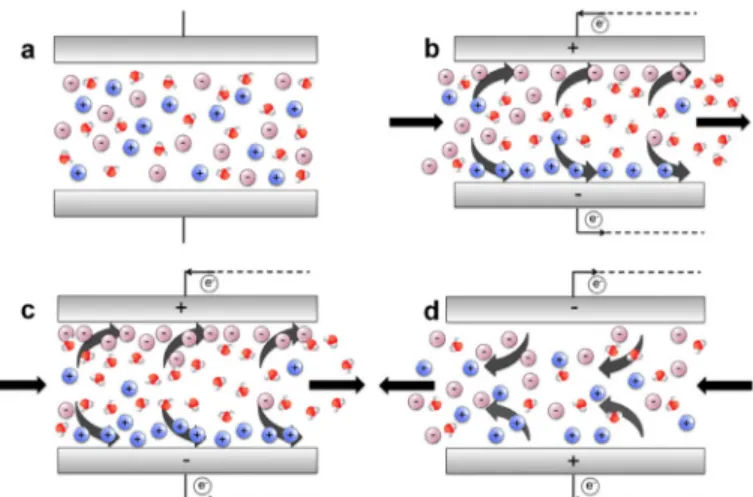
CDI uses high-surface-area electrodes to adsorb significant quantities of ions from water in an electrochemical double layer formed at a solid/electrolyte interface, thereby resulting in desalination (see Fig. 1) [2].Carbon materials (aerogel, CNT) are ideal electrode materials because of their low electrical resistivity (<40 mΩ·cm), high specific surface area (400-1100 m2/g), and controllable pore size distribution (<50 nm). However, a particular
drawback associated with the use of carbon-based electrodes for fundamental CDI studies is that they often demonstrate irregular geometries and a multitude of characteristic pore sizes that can complicate the modeling of unsteady ion transport. CNT carpet electrodes posses a well-defined pore structure and have been used in the past for supercapacitor applications.
Figure 1. Schematic of the CDI process. (a) Feed water in CDI cell before voltage is applied. (b) Voltage is applied and ions begin to migrate according to the applied potential. (c) Electrodes become saturated with ions and desalinated stream is purged from the CDI cell. (d) After fresh feed water enters the cell, the applied voltage is partially reversed so that ions desorb from the electrodes resulting in brine that is discharged, and the next cycle begins.
However, the application of CNT carpet electrodes to CDI is complicated by the fact that typical diffusion barriers and catalysts used in the growth of CNT carpets, e.g., tantalum and iron, are easily corroded in aqueous salt solutions. Corrosion compromises the mechanical and electrical connection of the CNT carpet to the current collector and introduces faradaic reactions that can obscure the charging dynamics of the EDL [3, 4].
In order to avoid this electrochemical limitation, thermally-grown CNT carpets were
diffusion bonded to gold-coated titanium current collectors and the catalyst-supporting substrates were removed to ensure robust electrical and mechanical connection while preserving the aligned geometry of CNT carpets [5]. Thus, this process provides a useful means to fabricate model electrode geometries amenable to theoretical analysis under typical CDI operating conditions. EXPERIMENTAL DETAILS
Carbon nanotube carpets were grown by chemical vapor deposition (CVD) [6]. Silicon growth substrates were prepared by sequentially depositing a 20 nm thick Al2O3 diffusion barrier
and a 5 nm thick film of Fe catalyst layer using electron-beam deposition. Growth was
performed in a 2.54 cm quartz furnace tube. Following a 15 min purge in a H2/He atmosphere,
the growth substrate was annealed by ramping the furnace temperature to 750 °C followed by a 3 minute anneal at temperature, while maintaining a flow of H2 and He at 400 sccm and 100 sccm,
respectively. CNT growth was then initiated by flowing C2H4 at 200 sccm. Distinct CNT carpet
heights were obtained by adjusting the duration of the CVD growth step.
In order to provide robust electrical and mechanical integrity of the CNT electrode, a gold (Au) diffusion bonding procedure was developed to selectively transfer the CNT carpets to a suitable current collector (Fig. 2a). Titanium (Ti) was chosen as the current collector due to its electrochemical-compatibility and favorable adhesion characteristics. A 0.8 mm thick Ti sheet was cut into 3 x 2 cm tabs and a 200 nm layer of Au was deposited onto one side. A
discontinuous Au film was deposited on the top of the CNT carpet using an electron-beam deposition process. Following Au deposition, the CNT substrate was cleaved into 1 x 1 cm
squares. A compression jig, machined from titanium plates and thoroughly cleaned with
detergent, isopropanol, acetone and DI water, was used to clamp the current collector and CNT substrate together, such that the deposited Au films on the respective surfaces were brought into close contact. The jig was assembled with Ti bolts using a torque wrench (typically 120 N·cm) to provide a consistent contact pressure.
Diffusion bonding was performed in a 3-inch tube furnace under a reducing atmosphere. The temperature profile for the bonding step was determined by calculating the thermal dose. The self-diffusion coefficient of Au and thermal dose were calculated, respectively, from [7]
𝐷𝐷 = 𝐴𝐴𝐴𝐴𝐴𝐴𝐴𝐴 �−𝑅𝑅𝑅𝑅𝑄𝑄�, (1) and 〈𝐴𝐴2〉 = ∫ 𝐷𝐷𝑡𝑡1 𝑡𝑡𝑜𝑜 𝑑𝑑𝑡𝑡 + ∫ 𝐷𝐷 𝑡𝑡2 𝑡𝑡1 𝑑𝑑𝑡𝑡, (2)
where D is the self-diffusion coefficient (cm2/s) for Au, A is the frequency factor (grain
boundary, 0.0062 cm2/s for Au), Q is activation energy (20.2 kJ/mol for Au) [7], R is Boltzmann constant (0.00831 kJ/( K·mol)), T is the thermodynamic temperature and t is the time in seconds. The thermodynamic temperature was assessed as T T v t= + ⋅ with T0 T 0 = 298K and
νT = 0.13 °C/s.
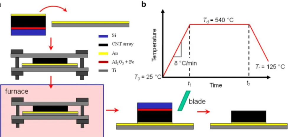
To obtain a strong bond between the CNT carpet and the current collector, we chose a thermal dose of 2〈𝐴𝐴2〉. After placing the sample in the furnace, the temperature was ramped from
room temperature to 540°C at a rate of 8°C/min and held for a period of time (t1 - t2 in Fig. 2b).
Following the temperature dwell period the furnace temperature was reduced to 125°C at 8 °C/min. At lower temperatures the cooling rate decreased since active cooling was not employed. Upon removal of the jig from the furnace and disassembling, the silicon growth substrate was then removed by inserting a razor blade between the CNT substrate and the Ti substrate to delaminate the Si substrate from the CNT carpet.
Figure 2. Diagram of the CNT carpet electrode fabrication process.
Cyclic voltammetry (CV) and potentiostatic characterization (Eco Chemie Autolab PGSTAT 100) were performed using a three electrode cell comprised of the CNT working electrode, a platinum mesh counter electrode (Alfa Aesar) and an Ag/AgCl reference electrode (Beckman Coulter, A57194). Solutions of NaCl in deionized water were prepared with molar concentrations ranging from 20 – 90 mM and had a typical pH of 5.4 during testing. CV scans were performed over a voltage range of 0.05 to 0.55 V at a scan rate of 30 mV/s and repeated 5 times at each concentration after an initial break-in cycle. Potentiostatic testing was conducted by initially
equilibrating the cell to the open circuit voltage (OCV), typically 180 - 220 mV. The applied voltage was then stepped to the desired voltage (100, 200, or 300 mV above OCV) and held for 5 minutes. The working electrode was then discharged by returning the cell potential to the OCV value and data was collected for an additional 5 minutes. The sampling frequency during the steps was 100 Hz for the initial 10 s and 10 Hz for the remaining 290 s.
DISCUSSION
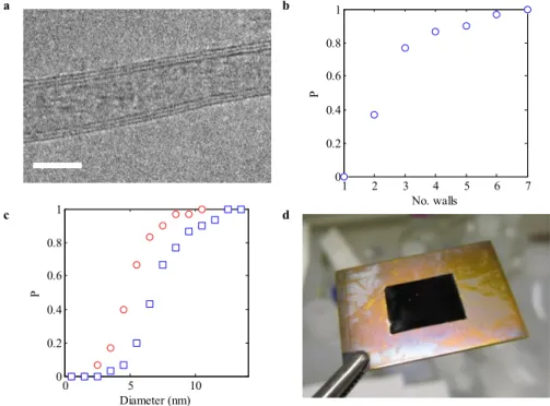
The geometric characteristics of the as-grown CNT were characterized using TEM as shown in Fig. 2a-c. The CNT were found to be composed of multiple walls with three being the typical number. The average inner and outer diameters of the CNT were 5.6±1.8 nm and 7.7±2.2 nm, respectively.
Figure 3. (a) Transmission electron micrograph of a typical multiwall CNT produced via CVD comprised of 3 walls. Scale bar: 5 nm. (b) Cumulative distribution of CNT wall number. (c) Cumulative distribution of the CNT inner ( ) and outer ( ) diameters. (d) Transferred CNT electrode fabricated using a 2〈𝐴𝐴2〉 thermal dose. The 1 x 1 cm2 CNT carpet sits at the center of
the 3 x 2 cm2 Ti current collector.
In order to assess the integrity of the bond formed between the CNT array and the Ti current collector (Fig. 3d), we immersed several fabricated electrodes subjected to different thermal doses in DI water for 100 hours before drying the electrode to check for capillary-induced delamination of the CNT carpet from the current collector. Three characteristic CNT carpet heights were obtained following the optimized transfer process: h = 8 μm (Ap = 0.908 cm2),
h = 21 μm (Ap = 0.859 cm2) and h = 29 μm (Ap = 0.796 cm2).
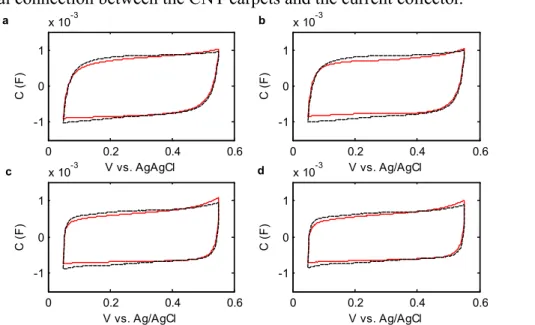
A typical set of CV curves obtained for the fabricated electrodes is shown in Fig. 4. All of the fabricated electrodes were found to be similar in that they did not demonstrate redox peaks consistent with pristine (unoxidized) nature of the CNT and the non-faradaic behavior of Au and
a b c d 1 2 3 4 5 6 7 0 0.2 0.4 0.6 0.8 1 No. walls P 0 5 10 0 0.2 0.4 0.6 0.8 1 Diameter (nm) P
passivated Ti in the investigated potential range. The fast charge behavior was consistent with good electrical connection between the CNT carpets and the current collector.
Figure 4. CV curves for a CNT electrode with h = 21 μm for (a) 20 mM, (b) 50 mM, (c) 70 mM and (d) 90 mM. The solid and dashed curves represent averaged CV behavior before and after potentiostatic testing, respectively. Scan rate: 30 mV/s.
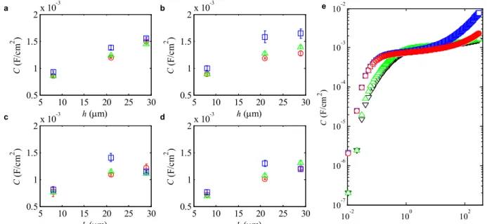
Potentiostatic measurements (Fig. 5) above the OCV (Cl¯ adsorption) demonstrated the expected behavior of linearly increasing capacitance with increasing carpet height. Due to the small size of the samples prepared we were unable to obtain a BET surface area. However, assuming a specific capacitance dominated by the Stern layer (C* ≈ 10 - 20 μF/cm2) [8] and
exohedral adsorption with C ≈ 1.5 mF/cm2, h = 29 µm, d = 7.7 nm, we estimate the solid fraction of the CNT array as 𝜑𝜑 = 𝑑𝑑 4ℎ⁄ (𝐶𝐶 𝐶𝐶⁄ − 1) ≈ 0.005 − 0.01 in agreement with the observed ∗
number density of CNT characterized using SEM (~1010 cm-2). Overall, the capacitive behavior
of the fabricated electrodes was consistent with the notable exception of the tallest carpet height (h = 29 μm), which demonstrated non-monotonic and anomalously large capacitances with increasing concentrations when integrating over the entire scan period due to an anomalous current during later stages of the scan (see Fig. 5e). By restricting the integration period to the asymptotic region of the initial charging period, we obtained capacitance values plotted in Fig. 5a-d for h = 29 μm. The specific cause for this behavior continues to be investigated. CONCLUSIONS
Aligned CNT carpets with uniform size distributions were grown using thermal CVD. A diffusion bonding process was successfully used to transfer the CNT carpets from the growth substrate to a titanium current collector. By tuning the thermal dose during the diffusion bonding process, mechanically robust attachment was obtained as assessed by capillarity-induced
delamination tests. Cyclic voltammetry scans demonstrated the electrical integrity of the bonding process and showed almost ideal capacitive behavior with an absence of faradaic side-reactions in the investigated potential window. Potentiostatic measurements demonstrated behavior consistent with typical specific capacitances at the lower concentrations tested. However, at higher salt concentrations, non-monotonic deviations and anomalous currents at the late stage of
0 0.2 0.4 0.6 -1 0 1 x 10⁻³ a V vs. AgAgCl C ( F) 0 0.2 0.4 0.6 -1 0 1 x 10⁻³ b V vs. Ag/AgCl C ( F) 0 0.2 0.4 0.6 -1 0 1 x 10⁻³ c V vs. Ag/AgCl C ( F) 0 0.2 0.4 0.6 -1 0 1 x 10⁻³ d V vs. Ag/AgCl C ( F)
charging were observed. Future research efforts will aim to further characterize CNT carpet electrodes fabricated using the diffusion bonding process to understand the observed
electrochemical behavior and fully characterize dynamic response behavior during charging and discharging.
Figure 5. Potentiostatically-measured capacitance normalized by electrode plan area, Ap, for (a)
no = 20 mM, (b) no = 50 mM, (c) no = 70 mM and (d) no = 90 mM with step potentials of ( ) 100
mV, ( ) 200 mV and ( ) 300 mV above the OCV. (e) Potentiostatic charging curves (h = 29 μm) at a step potential of 300 mV for ( ) no = 20 mM, ( ) no = 50 mM, ( ) no = 70 mM and
( ) no = 90 mM.
ACKNOWLEDGEMENTS
H.M. and E.N.W. would like to thank the King Fahd University of Petroleum and Minerals in Dhahran, Saudi Arabia, for funding the research reported in this paper through the Center for Clean Water and Clean Energy at MIT and KFUPM. R.E. acknowledges funding received from the Irish Research Council for Science, Engineering, and Technology, co-funded by Marie Curie Actions under FP7.
REFERENCES
1. T. Humplik, J. Lee, S. C. O'Hern, B. A. Fellman, M. A. Baig, S. F. Hassan, M. A. Atieh, F. Rahman, T. Laoui, R. Karnik and E. N. Wang, Nanotechnology 22 (292001) (2011).
2. Y. Oren, Desalination 228, 10-29 (2008).
3. P. M. Biesheuvel and M. Z. Bazant, Phys. Rev. E 81 (031502) (2010). 4. P. M. Biesheuvel, Y. Fu and M. Z. Bazant, Phys. Rev. E 83 (061507) (2011).
5. R. Cross, A. C. Baratunde, T. Fisher, X. Xu, K. Gall and S. Graham, Nanotechnology 21 (445705) (2010).
6. A. J. Hart and A. H. Slocum, J. Phys. Chem. B 110, 8250-8257 (2006).
7. W. F. Gale and T. C. Totemeier, Smithells Metals Reference Book, (Elsevier, 2004). 8. J. Huang, B. G. Sumpter and V. Meunier, Chem. Eur. J. 14, 6614-6626 (2008).
5 10 15 20 25 30 0.5 1 1.5 2x 10 -3 h (µm) C (F/ cm 2 ) 5 10 15 20 25 30 0.5 1 1.5 2x 10 -3 h (µm) C (F/ cm 2 ) 5 10 15 20 25 30 0.5 1 1.5 2x 10 -3 h (µm) C (F/ cm 2 ) 5 10 15 20 25 30 0.5 1 1.5 2x 10 -3 h (µm) C (F/ cm 2 ) a b c d 10-2 100 102 10-7 10-6 10-5 10-4 10-3 10-2 t (s) C (F /cm 2 ) e