First International Conference on Bio-based Building Materials June 22nd - 24th 2015 Clermont-Ferrand, France
NUMERICAL MODELING OF RAMMED EARTH CONSTRUCTIONS: ANALYSIS
AND RECOMMENDATIONS
R. El Nabouch, Q.-B. Bui ,*, P. Perrotin, O. Plé, J.-P. Plassiard
Université de Savoie, LOCIE – CNRS UMR 5271, 73376 Le Bourget du Lac, France. *Corresponding author; e-mail: [email protected]
Abstract
Rammed earth (RE) material presents actually attracting interests in the context of sustainable development. In addition to low embodied energy, rammed earth constructions present interesting living comfort thanks to the substantial thermal inertia and the natural “moisture regulator” of the RE walls. This is why several researches have been recently carried out to study this material. However, comparing to other conventional materials (e.g. concrete), there is not yet sufficient results in the literature which enable to perform advanced studies in the case of extreme loadings (e.g. earthquake).
The paper presents firstly a review of the existing studies on RE, from the material characteristics to the structural behavior, from the experimental results to the numerical models. An analysis of these results is presented. Secondly, numerical simulations using a finite element code (ASTER) are engaged. The Drucker-Prager elasto-plastic model is adopted. Experimental results, coming from the literature, are used to calibrate the numerical simulation. The variability of the parameters (Young modulus, friction angle, cohesion …) and the relevance of the used model will be discussed. Finally, recommendations for future numerical and experimental studies will be presented.
Keywords:
Rammed earth; mechanical characteristics; numerical modeling; Drucker-Prager model.
1 INTRODUCTION
Buildings constructed by local materials are sustainable in the actual context. Indeed, local materials are generally bio-based that can be used without negative effects on the environment. The primary materials are extracted directly on the construction site (or near the site) like soil, stones, then they are, transformed in construction material with a very low manufacturing energy.
Several interests are found in the use of local materials, one of these intrests is creating a green building construction. A green building expand the conventional buildings with many criteria that concern utility, durability, comfort, and socio-economy .
The use of a sustainble material reduces the embodied energy coming from extraction, transportaion, manufacturing i.e. needed to make a product. Therefore one of the basics in using these materials is creating an environmentally friendly building and expanding effort to visualise an ecological world. An additional advantage lies in the increase of local employment, the social aspect is then favorable. One of the most common materials used in the past is rammed earth which is the object of this article. Today, rammed earth is attracting for sientific researches thanks to its chracteristics which make it a sustainable
material. The main objective of this article is to provide an accurate knowledge about the behavior and the mechanical characteristics of this material in building construction.The first part of this article will mainly analyse previous studies done on the rammed earth material and structure. Some guidelines on this material will also be presented. The second part of the article deals with numerical simulations on rammed earth wallets, carried out at two different scales in a 3D finite element code (Aster). An axial compression test and a diagonal compression test. The Drucker-Prager model was used in this study. Thereafter, the role of different mechanical parameters will be discussed. 2 BACKGROUND
Together with other forms of local earthen construction, rammed earth has a long and continuous history throughout many regions of the world. The earth has been used as a construction material because it is available everywhere, recyclable and provides an interesting thermal behavior.
[Avrami 2008] estimates that more than a half of the world population lives in earth constructions. A great number of earth constructions can be found in France, in Germany, in Spain, in North Africa, in Australia, in North and South America and in Asia (China, Japan, …).
Despite the advantages of this construction material, some countries where the population still lives in earthen buildings are subjected to high seismic hazard. Unfortunately earth materials have moderate mechanical performances. This material is less resistant than conventional building materials. Most of these problems should be overcome by a better knowledge of the mechanical behavior of the material in building construction.
2.1 Rammed earth
Rammed earth walls are manufactured by compacting soil between temporary formworks (wooden or steel forms). The principal binder of the grains is the clay. The earth is compacted into layers of approximately 15 cm by the use of a manual or pneumatic rammer. The average thickness of the wall is 50 cm. Fig.1 shows a construction site of rammed earth at Mablomong school.
Fig. 1 : Rammed earth construction at Mablomong school(www.specifile.co.za/).
Today, there are essentially two types of rammed earth: traditional rammed earth and modern manufactured rammed earth. The traditional rammed earth is manufactured by a manual rammer between wooden formworks (Fig.2). Generally made with only clay, it is called non stabilized rammed earth.
Fig. 2: Traditional house made of rammed earth in Auvergne, France (www.french-property.com).
Concerning the modern rammed earth, nowadays numerous are stabilized with a hydraulic binder (cement agent) to increase its performances (Fig.3). The manual rammer is replaced by a more powerful pneumatic rammer that increases the rapidity of manufacturing and the density of the material. It is also noted that prefabrication of modern rammed earth has been also developed.
Due to the fact that heritage of rammed-earth buildings in Europe needs to be preserved; unstabilized rammed-earth is now the center of several scientific investigations.
Fig. 3 An example of modern earthen structure: the Oaxaca School of Plastic Arts in Mexico
(www.dailytonic.com).
2.2 Advantages of rammed earth
Environmental benefit in industrialized countries
Earth construction assumes in this particular context, an environmental advantage through a building life cycle: from construction, operation, maintenance, renovation, and demolition.
Due to its low embodied energy, rammed earth construction had become very competitive when compared to conventional materials [Morel 2001].
Thermal performance
Several research studies have recently been conducted to study the thermal properties of rammed earth. In cold climates, rammed earth serves as thermal mass, the thick walls provide thermal energy storage, absorbing heat from the sun during the day to be released slowly at night.
[Taylor 2004] investigated the thermal performance of rammed earth walls in Australia during summer, the results of their study showed that the high thermal mass of the rammed earth was able to improve the thermal behavior of the earth construction.
Socio-economic benefit
Using mostly manual labor, the use of rammed earth also has the socio-economic advantage of creating local jobs.
2.3 Strengthening solutions applied for rammed earth
Many studies have shown the effect of strengthening the rammed earth walls. [Hu 2011] showed the efficiency of the reinforcement with horizontal and vertical wire mesh strips on improving the seismic capacity of the rammed earth wall. However, the relevancy of these reinforcement techniques in the case of real structure is still questionable.
Another study done by [Gomes 2011] presents results of a parametric study using Finite Element method on a properly designed rammed earth construction in Portugal, considering several strengthening solutions. This study shows that an adjustment between ecology and safety is attained if earth walls are bound together by a set of RC frames even in strong seismicity areas. Damage can also be reduced if the earth is stabilized with cement or other binders. However, the numerical results presented in that study were not validated by an experimental investigation, some results are disputable.
Until today, there are few researches that study the experimental dynamic behavior of rammed earth structures. Among them, [Bui 2011] preformed an
were identified by in-situ dynamic measurements, then a comparison with the empirical formulas of Eurocode was done indicating a good accordance .This study could be used to assess the seismic vulnerability of the existing buildings.
3 EARTH CONSTRUCTION GUIDLINES Some countries have their earth construction standards. Unfortunately, these guidelines are based on conventional materials (e.g. concrete) studies. Consequences, several clauses of these standards need to be improved. This section provides guidelines and codes that exist in the literature.
Many countries have set out structural design and structural strengthening of rammed earth also requirements for formwork, methods of construction, testing and curing of rammed earth.
Australia, the New Zealand and Mexico have specific regulations on earth construction. For example, the Australian Earth Building Handbook was published by [Walker 2002]. This handbook sets out the principles of good practice and recommended design guidelines, including structural values or earth-wall design. New Zealand has one of the most advanced legal regulations on earth construction. This is structured in three distinct parts:
[NZS 4297 1998]– Engineering design and earth buildings –establishes performance criteria for mechanical strength, shrinkage, durability, and thermal insulation and fire resistance;
[NZS 4298 1998] – Materials and workmanship for earth buildings – defines requirements for materials and workmanship.
[NZS 4299 1998] earth buildings not requiring specific design – this part is applicable for buildings with less than 600 m2 (or 300 m2 per floor).
Even for countries advanced in rammed earth design contradictions exist. For example, NZS 4297 code set a minimal thickness of the wall of 25 cm while the New Mexico code [Tibbets 2001] sets two different thicknesses, 45 cm for external wall and 30 cm for internal wall.
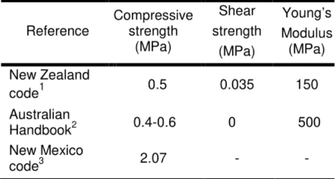
The recommended design values for rammed earth as proposed by the New Zealand and the Australian codes are summarized in Tab.1
4 MECHANICAL TESTS IN THE LITERATURE.
With the revival of this material in the context of sustainable building, several studies have been carried out recently to analyze its mechanical characteristics.
Tab.1: Recommended design values for rammed earth.
Reference Compressive strength (MPa) Shear strength (MPa) Young’s Modulus (MPa) New Zealand code1 0.5 0.035 150 Australian Handbook2 0.4-0.6 0 500 New Mexico code3 2.07 - - 1 [NZS 4297 1998]; 2 [Walker 2002]; 3 [Tibbets 2001]
[Miccoli 2014a] did a recent study about the mechanical behavior of earthen materials comparing to three earth materials: earth block masonry, rammed earth and cob. To have better knowledge on the structural behavior under static loads, a compression test and diagonal test have been conducted, as results of compression test, rammed earth wallets of 500 x 500 x 110 mm3, showed the highest compressive strength of all three types of earth constructions, the values of compressive strength are in the range of 3.4 to 4.0 MPa.
In another study, [Bui 2014] gives experimental results on tensile strengths. In this research local failure was conducted on 1000x1000x300 mm3 walls manufactured in the laboratory. Relationship between the compressive strength and the tensile strength in earth layer has been shown to be 0.11 fc, where fc the compressive strength. A compression test in the direction parallel and perpendicular of the layers have been also achieved.
Concerning the Young modulus, several studies were done, showing that the modulus of unstabilized rammed earth can vary from 100 MPa (old walls in the study of [Bui 2015a]) to 500 MPa (new walls in the study of [Bui 2009a]), however for the stabilized rammed earth [Miccoli 2014a] obtained a higher values for Young’s modulus that was equal to 4143 MPa. Summary of material properties for earthen materials found in the literature are shown in Tab. 2. A great dispersion is noted. This is due to many factors as the testing procedures, the workmanship, and the type of the soil.
Tab. 2: Mechanical characteristics of rammed earth.
Specimen dimensions(cm) (width x thickness x height) Compressive strength (MPa) Tensile strength (MPa) Young’s Modulus (MPa) Reference 20x20x40 1 0.17 500 [Bui 2014] Diameter=10 h=20 2.46 - 160 [Maniatidis 2008] 10x10x10 0.5-1.3 - - [Hall 2004] 50x11x50 3.73 - 4143 [Miccoli 2014a]
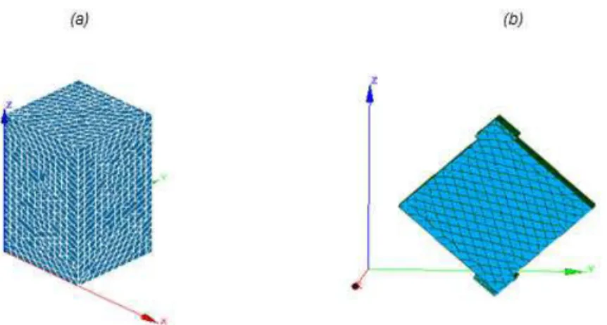
Fig.4 : Numerical model for uniaxial compression test (a) and diagonal compression test (b).
Regarding the parameters of cohesion and friction angle. Different values can be found in the literature. [Cheah 2012] found 45°-56° for cement-stabilized rammed earth specimens, 51° is found following [Bui 2014] with a cohesion equal to 0.1 fc, while [Miccoli 2014b] assumed that the friction angle is 37° in his model with a cohesion equal to 1.5 ft. [Nowamooz 2011] obtained a friction angle equal to 41° and a cohesion of 134 kPa.
5 NUMERICAL MODELLING
Most of the studies concerning the modeling of rammed earth found in the literature adopt very simple models by including very simple constitutive laws for this material. Some of these studies adopt either a linear elastic isotropic law [Gomes 2011] or elastic-perfectly plastic behavior to describe the behavior of rammed earth [Nowamooz 2011] and [Jaquin 2006]. [Micooli 2014b] used micro and macro modelling approaches in his modeling. Mohr-Couloumb failure criterion was used to simulate the behaviour of interfaces between layers and a strain rotating crack model was used to simulate the behavior of rammed earth, when comparing to the experimental results some uncertainties related to the model remain exsisting.
In this paper, the two different experiments existing in the litterature are modeled by using the Finite Element (FE) Aster code. This code enable to take into account the nonlinear behaviour of the material and two behaviour laws (in compression and in traction) can be considered differently. Two models are constructed by using 3D solid elements: the first models a specimen under axial compression and the second models a diagonal compression test on a wall. The results are compared to experimental results tested on rammed earth. The Drucker-Prager model is used.
The rammed earth was considered as homogeneous, isotropic continum. Fig.4(a) shows the specimen tested under compression a in previous study. The experimental results of [Bui 2009b] are used to calibrate the numerical model. The average dimensions of the specimens are (200x200x400) mm3. The results of diagonal compression tests presented in [Silva 2013] are also used to identify the corresponding
monotic displacement and using supports of 100 mm in length. Fig.4(b) shows the model done for the wall tested under diagonal compression test.
The boundary conditions adopted in both models suppose the bottom to be fixed, the load was applied by imposing vertical displacements at the upper part of the model.
5.1 The Drucker-Prager law
The Drucker-Prager law is selected because it is currently used in geomechanics. As most of experiments show an elasto-plastic behavior [Bui 2009b], the Drucker-Prager model is relevant. The behavior law is written:
F(σ , p)=σeq+
α
I1−R(p) =0 (1) Where a is a given coefficient and I1 = Tr (σ) and R is afunction of the cumulated plastic strain p (function of hardening), of type linear or parabolic. The parabolic hardening is chosen for our model
The parameters needed in the model are: The plastic stress,
( )
( )
ϕ ϕ σ sin cos − = 3 6c y (2) The Coefficient of independence in pressure,( )
( )
ϕ − ϕ = α sin sin 3 2 (3)Where ϕthe friction angle and c the cohesion.
Fig.5 shows the projection of the criterion of the Drucker-Prager which represents a cone.
Fig .6: (a) Behavior of the model under axial compression for f=36.8˚ (b) for f=45˚.
5.2 Calibration of the models and results
a. From the axial compression test
In this part the influence of the cohesion and friction is studied. In the modelling of the compression test , the Young’s modulus was assumed to be 100 MPa and the poisson ratio 0.23 [Bui 2013]. Based on the values found in the literature we limited the friction angle in the range of 36.8˚ to 45˚. Regarding the cohesion, different values were tested. Fig.6 shows the results obtained from tests and numerical simulation in terms of vertical load and vertical displacement for the axial compression test. Both the cohesion and friction angle affect the ultimate load, when these two parameters increase more important effect on the ultimate load can be observed. The assumtion of the Young’s modulus of 100 MPa might be appropriate regarding the initial stiffness obtained by the FE model that was identical to the experimental results. However the numerical simulations for the compression test of this specimen show a less gradual transition between elastic and plastic behavior. Regarding the friction angle, both angles (36,8˚ and 45˚) appear to be adequate for
obtaining the ultimate compressive load. For 36.8˚, the cohesion is equal to 250 kPa which is important for this type of material. [Bui 2014] and [NZS 4297] showed that the cohesion was about 0.07-0.1 × fc which was obtained following the Mohr-Coulomb theory. Therefore, the best estimation is a friction angle of 45˚ and a cohesion between 150 and 200 kPa.
b. From the diagonal compression test
The results of diagonal compression tests obtained in [Silva 2013] are used to identify the parameters of the Drucker-Prager model. The wall GSRE_7.5 was chosen. The results of uniaxial compressive tests obtained in that study were: compressive stength fc=1.09 MPa and Young’s modulus E=2858 MPa. The diagonal shear tests gave a shear strength of 0.18 MPa andashear modulus G=620 MPa. These values are greater than the values currently obtained for unstablised RE, this can be due to the fact that the wall in this study was stabilised by the addition of geopolymeric binder.
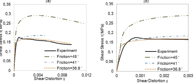
Fig. 7: Numerical and experimental results of the diagonal compression test, for E=2800 MPa. (a) Behavior of the model until the rupture, (b) Zoom in to identify the initial behavior.
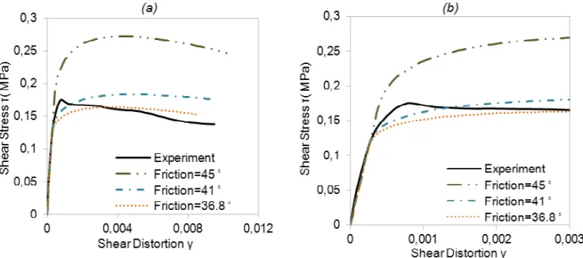
Fig. 8: Numerical and experimental results of the diagonal compression test, for E=1500 MPa. (a) Behavior of the model until the rupture, (b) Zoom in to identify the initial behavior.
Fig.9: (a) Max principal strain in the model for E= 1500 MPa (b) Experimental failure [Silva 2013].
However it should be noted that it exists an experimental envelope of the shear stress-shear strain curves. What means that some uncertainties remain for the curve chosen from the experimental process. The test procedure was simular to [ASTM 2002]. Following the ASTM E519-02 standard, the shear stress τ of the specimens is calculated as follows:
n A xP .707 0 = τ (4) Where P is applied load and An is the net area of the specimen. The shear strain (or shear distortion) γ is obtained by: h v g h g v ∆ + ∆ = γ (5) where ∆v is the vertical shortening of the panel, ∆h is the horizontal extension of the panel, and gv and gh are the vertical and horizontal gage lengths. In this FEM
model, we measure the ∆v and ∆h of two diagonal line of the specimen.
Fig. 4b shows the model constructed in the Aster code. In order to assess the influence of the mechanical characteristics, a parametrical study was performed. In this part it is assumed to fix the cohesion to a specific value and vary the angle of friction. By using the relationship proposed by [Bui 2014] and [NZS 4297 1998] (c = 0.07-0.1 × fc), a cohesion of 100 kPa was chosen. The friction angle varied between 36.8˚ and 45˚
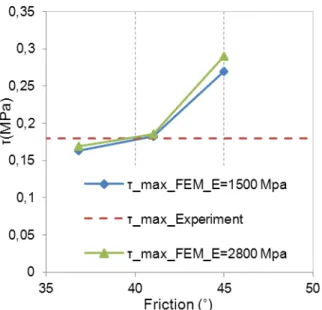
The same study was done for two different Young’modulus. Indeed, following [Silva 2013], a Young’s modulus of 2800MPa was obtained from uniaxial compression tests while with the diagonal test, a shear modulus of 620MPa was obtained. Following the elastical theory, this shear modulus corresponds to a Young’s modulus of 1500 MPa.
Fig. 10: Variation of the ultimate shear stress in function of the friction angle.
From Figs 7 and 8, all models reproduce the ultimate shear stress except the models with the friction angle equal to 45°. However the slope of the model with E=1500 MPa was more adapted to the experimental one than that of E=2800 MPa.
From Fig. 10, the best friction angle was found to be 41°. Fig. 9 presents the maximum principal strains obtained from an imposed vertical displacement of 1 mm for the best model which was for the following parameters E=1500 MPa and f=41˚. The model shows that the damage is concentrated in the middle and at supports. This model enables to reproduce the zone of failure which had been obtained with the experiment. Although the typical “shear peak” was not reproduced by the numerical model, the last one was able to reproduce the post-peak softening phase of the material. It reproduced the elasto-plastic behavior of rammed earth in this case.
6 CONCLUSIONS
The work carried out in this paper intends to fill the bibliographical gap and to initiate technical discussion about the resistant of rammed earth and its important parameters. The mean objective was to identify these parameters. The compression behavior of the rammed earth was simulated using the Drucker-Prager criterion provided by code Aster. The numerical results showed a good agreement with the experimental results of the compression tests. Regarding the simulation of the diagonal compression tests, the results of the shear stress-strain curve were adapted to the experimental ones. The damage pattern showed that the influence was mostly vertical in the middle of the wall. Finally the cohesion and the friction angle and the Young’s modulus were adapted comparing the experimental results with the numerical one. The experimental values of Young’s modulus were chosen for the model then adapted with small variation for a better adjustment. It was found that for the elastic phase the numerical curves fit well to the experimental ones indicating the accuracy of the values set for the Young’s modulus. Below the elastic phase, the study reveals the limit of this model in producing a less gradual evolution between elastic and plastic behavior.
From the results obtained from this study and those of other studies exiting in the litterature ([Bui 2014], [Bui 2015b], [Miccoli 2014b]), the cohesion can be taken of (0.07-0.1) × fc; the friction angle can be taken about of 40-45°. The variation is due to the characteristic variability of the used soil, the manufacturing process (manufacturing water content, compaction energy, confinement effect).
The present paper showed that the Drucker-Prager model could reproduce the static nonlinear behavior obtained experimentally on RE specimens and RE walls. This model will be checked in the cases of cyclic and dynamic loadings. This validation will be important to simulate the earthquake behavior of RE structures. For the validation, addition tests on earth material and walls are being conducted in the authors’ laboratory. Several RE walls were constructed with different slenderness. These walls will be submitted to pushover tests to simulate horizontal seismic actions. From these results, mechanical and seismic performances of RE structures will be studied.
7 ACKNOWLDGEMENT
This research is funded as part of the project PRIMATERRE - ANR-12-VBDU-0001-01-Villes et Villes et Bâtiments Durables.
8 REFERENCES
[Avrami 2008] Avrami, E.; Guillaud, H.; Hardy, M.; Terra literature review. An overview of research in earthen architecture conservation. Los Angeles, The Getty Conservation Institute, 2008.
[ASTM 2002] ASTM E519-02, Standard Test Method for Diagonal Tension (Shear) in Masonry Assemblages. ASTM International, West Conshohocken, PA.2002.
[Bui 2011] Bui, Q.B.; Morel, J.C.; Hans, S.; Do, A.P.; First exploratory study on dynamic characteristics of rammed earth buildings. Engineering Structures, 2011, 33, 12, 3690–3695.
[Bui 2009a] Bui, Q.B.; Morel, J.C.; Hans, S.; Meunier, N.; Compression behaviour of non-industrial materials in civil engineering by three scale experiments: the case of rammed earth. Materials and structures, 2009, 42, 8, 1101-1116.
[Bui 2009b] Bui, Q.B.; Morel, J.C.; Assessing the anisotropy of rammed earth, Construction and Building Materials, 23, pp. 3005-3011, 2009.
[Bui 2013] Bui, Q.B.; Morel, J.C.; Hans S.; Walker, P.; Water effects on the mechanical characteristics of rammed earth buildings: a double-edged sword. Construction and Building Materials, 2013
[Bui 2014] Bui, T.T.; Bui, Q.B.; Limam, A.; Maximilien, S.; Failure of rammed earth walls: from observations to quantifications. Construction and Building Materials, 2014, 51, 295-302.
[Bui 2015a] Bui, Q.B.; Morel, J.C.; First Exploratory Study on the Ageing of Rammed Earth Material. Materials, 2015, 8, 1, 1-15.
[Bui 2015b] Bui, T.T.; Bui, Q.B.; Limam, A.; Morel, J.C.; Discrete element modeling of rammed earth walls, ICREC 2015, Feb. 2015, Perth, Australia.
[Cheah 2012] Cheah, J.S.J.; Walker, P.; Evaluating shear test methods for stabilised 467 rammed earth.In:Proceeding of the ICE- Construction Materials, April 2012, 165, 6, 325–334.
[Gomes 2011] Gomes, MI.; Lopes, M.; Brito, J.; Seismic resistance of earth construction in Portugal, Engineering Structures, 2011, 33, 3, 932-941.
[Hall 2004] Hall, M.; Djerbib, Y.; Rammed earth sample production: context, recommendations and consistency, Construction and Buildings Materials, 2004, 18, 281-6.
[Hu 2011] Hu, R.R.; Dong, Y.G.; Analysis for the Shake Table Test of Rammed Earth Wall Panels: International Conference on Structures and Building Materials, 7-9 January 2011, Guangzhou, China: Thomas Wohlbier, 21-25.
[Jaquin 2006] Jaquin, P.; Augarde, C.; Analysis of historical rammed earth construction. In: P.B. Lourenço, P. Roca, C. Modena, S. Agrawal ,ed. Proc. 5th Int. Conf. Structural Analysis of Historical Constructions, New Delhi, India, 2006.India: Structural Analysis of Historical Constructions ,1091-1098, ISBN: 972-8692-27-7.
[Maniatidis 2008] Maniatidis, V.; Walker, P.; Structural capacity of rammed earth in compression. Journal of Material in Civil Engineering, 2008, 20, 230-238. [Miccoli 2014a] Miccoli, L.; Müller, U.; Fontana, P.; Mechanical behavior of earthen materials: A comparison between earth block masonry rammed earth and cob. Construction and Building Materials, 2014, 61,327-339.
[Miccoli 2014b] Miccoli, L.; Oliveira, D. V.; Silva, R. A.; Müller, U. et al.; Static behaviour of rammed earth: experimental testing and finite element modelling. Materials and Structures, 2014 1-14. [Morel 2001] Morel, J.C.; Mesbah, A.; Oggero, M.; Walker, P.; Building houses with local materials:
means to drastically reduce the environmental impact of construction. Building and Environment, 2001, 36, 1119-26.
[Nowamooz 2011] Nowamooz, H.; Chazallon, C.; Finite element modelling of a rammed earth wall. Construction and Building Materials, 2011,25,4, 2112-2121.
[NZS 4297 1998], New Zealand Standard. Engineering Design of Earth Buildings. StandardNew Zealand, Wellington, New Zealand, 1998.
[NZS 4298 1998] New Zealand Standard. Materials and Workmanship for Earth Buildings. Standard New Zealand, Wellington, New Zealand, 1998.
[NZS 4299 1998], New Zealand Standard. Earth Buildings Not Requiring Specific Design. Standard New Zealand, Wellington, New Zealand, 1998.
[Silva 2013] Silva, R.A.; Oliveira, D.V.; Miranda, T.; Cristelo, N. et al. ; Rammed earth 496 construction with granitic residual soils: The case study of northern Portugal, Construction and 497 Building Materials, 2013, 47, 2013, 181-191.
[Taylor 2008] Taylor, P.; Fuller, R.J.; Luther, M.B.; Energy use and thermal comfort in a rammed earth office building, Energy Build, 2008, 40, 793-800. [Tibbets 2001] Tibbets, J.M.; Emphasis on rammed earth—The rational. Interaméricas Adobe Builder, 2001, 9, 4-33.
[Walker 2002] Walker, P.; Standards Australia The Australian Earth Building Handbook. Sydney, Australia: Standards Australia, 2002.